

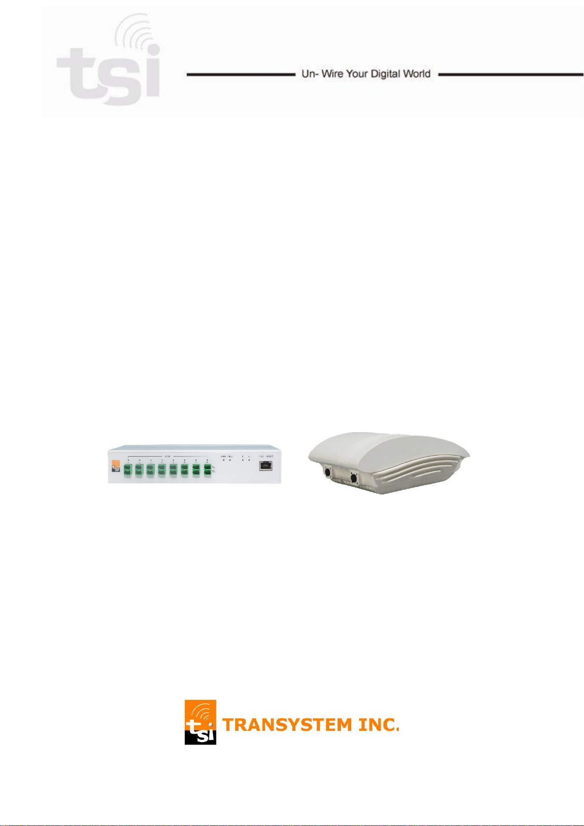
Distributed Antenna System
sDAS+ IFDSP19U21U
User Manual
(For BC25 / BC66)
Revision 1.3
03/05/2019
WARNING. This is NOT a CONSUMER device. It is designed for installation by
FCC LICENSEES and QUALIFIED INSTALLERS. You MUST have an FCC
LICENSE or express consent of an FCC License to operate this device.
Unauthorized use may result in significant forfeiture penalties, including
penalties in excess of $100,000 for each continuing violation.
Note:
This equipment has been tested and found to comply with the limits for a Class
B digital device, pursuant to part 15 of the FCC Rules. These limits are designed
to provide reasonable protection against harmful interference in a residential
installation. This equipment generates, uses and can radiate radio frequency
energy and, if not installed and used in accordance with the instructions, may
cause harmful interference to radio communications. However, there is no
guarantee that interference will not occur in a particular installation. If this
equipment does cause harmful interference to radio or television reception,
which can be determined by turning the equipment off and on, the user is
encouraged to try to correct the interference by one or more of the following
measures:
- Reorient or relocate the receiving antenna.
- Increase the separation between the equipment and receiver.
- Connect the equipment into an outlet on a circuit different from that to which
the receiver is connected.
- Consult the dealer or an experienced radio/TV technician for help.
WARNING!
Use only authorized and approved antennas, cables and/or coupling devices!
The use of unapproved antennas, cables or coupling devices could cause
damage and may be of violation of FCC regulations. The use of unapproved
antennas, cables and/or coupling devices is illegal under FCC regulations and
may subject the user to fines.
RF Exposure Warning: This equipment complies with FCC radiation exposure
limits set forth for a controlled environment. The Remote Unit should be
operated with a minimum distance of 28cm (11 in) between antenna and your
body.
Use only authorized and approved antennas, cables and/or coupling devices!
The use of unapproved antennas, cables or coupling devices could cause
damage and may be of violation of FCC regulations.
Note to the professional installer: the output power must be adjusted such that it does not
exceed the certified level as indicated in the certification filing to ensure that the booster is
operating in its linear range. Furthermore, the external antenna model come with a 9 dBi
panel type antenna which has been evaluated and fully comply with the relevant FCC rules.
The use of any other antenna is subject to a separate evaluation to ensure that the
resulting EIRP does not exceed the allowed EIRP limit as specified in 47 CFR Part
24.238(a) for LTE Band 25 and Part 27.53(h) for LTE Band 66 and that it complies with the
uncontrolled RF exposure limit.

Table of Content
1 HARDWARE OVERVIEW .................................................................................. 4
1.1 HEU Hardware ........................................................................................................ 4
1.1.1 Port .................................................................................................................. 4
1.1.2 LED ................................................................................................................. 6
1.2 RAU Hardware ........................................................................................................ 7
1.2.1 Port .................................................................................................................. 7
1.2.2 LED ................................................................................................................. 7
2 SDAS+ CONNECTION ........................................................................................ 8
2.1 Topology Overview ................................................................................................. 8
2.2 Connecting HEU & RAU ......................................................................................... 8
3 SYSTEM PROVISIONING ................................................................................ 10
3.1 Topology Setting ................................................................................................... 10
3.2 DAS Setting & Calibration ..................................................................................... 11
4 SYSTEM MONITORING ................................................................................... 12
4.1 System Info. .......................................................................................................... 12
4.2 Power Info. ........................................................................................................... 13
3
sDAS+ User Manual
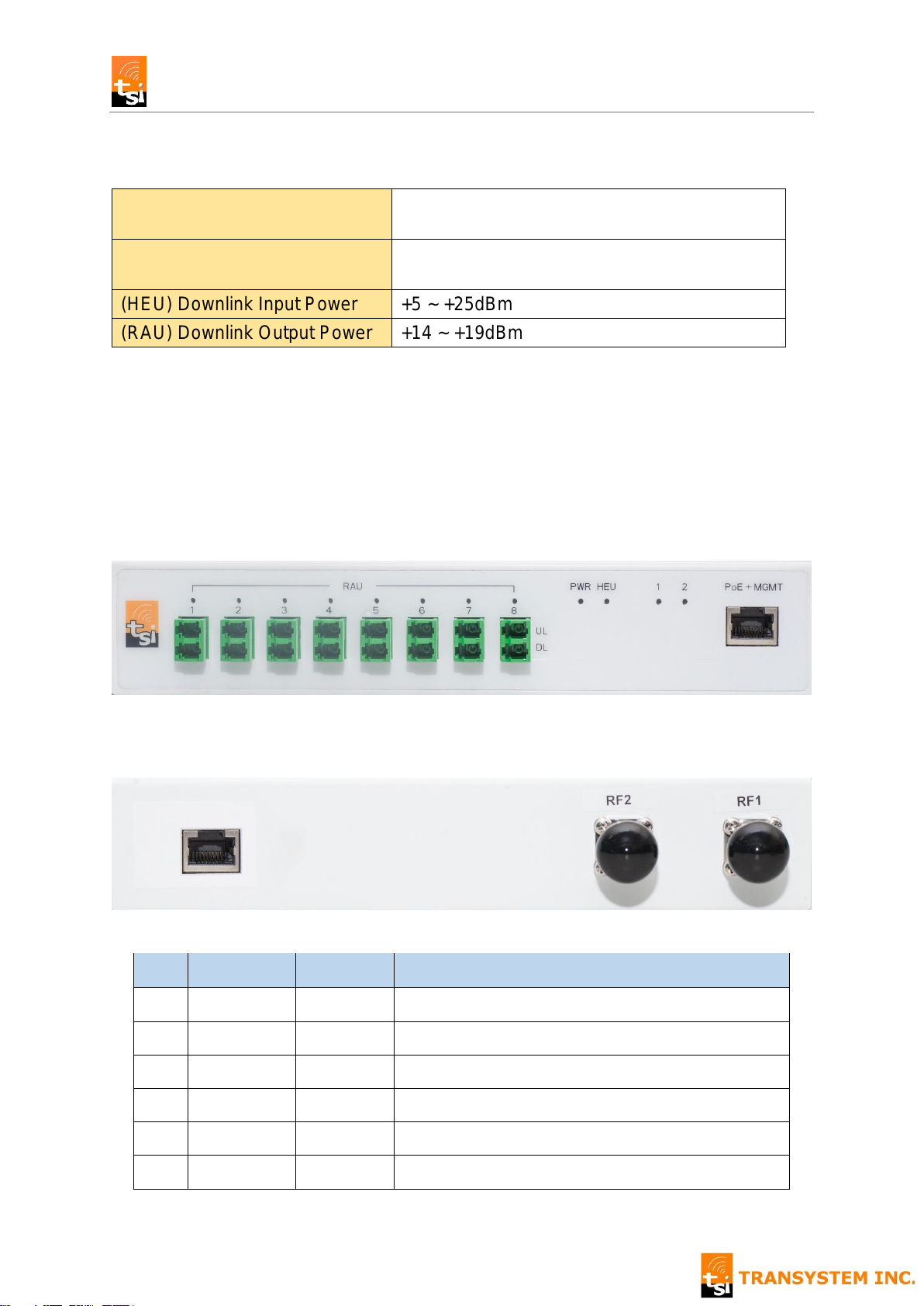
RF1 Frequency Range
Uplink / Downlink
Extended PCS (Band 25)
1850 ~ 1915MHz / 1930 ~ 1995MHz
RF2 Frequency Range
Uplink / Downlink
Extended AWS (Band 66)
1710 ~ 1780MHz / 2110 ~ 2180MHz
(HEU) Downlink Input Power
+5 ~ +25dBm
(RAU) Downlink Output Power
+14 ~ +19dBm
No.
Item
Interface
Description
1
RAU 1
LC/APC
Connect to 1st RAU UL/DL by fiber
2
RAU 2
LC/APC
Connect to 2nd RAU UL/DL by fiber
3
RAU 3
LC/APC
Connect to 3rd RAU UL/DL by fiber
4
RAU 4
LC/APC
Connect to 4th RAU UL/DL by fiber
5
RAU 5
LC/APC
Connect to 5th RAU UL/DL by fiber
6
RAU 6
LC/APC
Connect to 6th RAU UL/DL by fiber
1 2 3 4 5 6 7 8 9
10 11 12
1 HARDWARE OVERVIEW
1.1 HEU Hardware
1.1.1 Port
Front Panel View
Rear Panel View
4
sDAS+ User Manual
7
RAU 7
LC/APC
Connect to 7th RAU UL/DL by fiber
8
RAU 8
LC/APC
Connect to 8th RAU UL/DL by fiber
9
PoE+MGMT
RJ45
Connect with PoE injector for Power & Control
10
Reserved
RJ45
No function
11
RF 2
N-Female
Connect with BTS RF Signal 1
12
RF 1
N-Female
Connect with BTS RF Signal 1
5

sDAS+ User Manual
RAU
1-8
Green
RAU has been provisioned & calibrated
Flash Green
1. RAU has been provisioned, and waiting
for calibration, or
2. Firmware upgrade
Red
1. RAU alarm, or
2. RAU link failed
Dark
RAU has not been provisioned yet
PWR
Green
Power on
HEU
Green
Normal mode
Flash Green
Firmware upgrade
Red
HEU Alarm
(RF)
1 & 2
Green
RF signal detected
Dark
No RF signal
1.1.2 LED
6

sDAS+ User Manual
No.
Item
Interface
Description
1
DL
LC/APC
Connect to HEU DL port by fiber
2
UL
LC/APC
Connect to HEU DL port by fiber
3
PoE
RJ45
Connect with PoE injector for power
4
Reserved
RJ45
No function
5
RF2
N-Female*
Connect an external antenna**
6
RF1
N-Female*
Connect an external antenna
PWR
Green
Power on
Fiber
Green
Provisioned & calibrated
Flash Green
1. Optical power detected & ready for
provisioning & calibration, or
2. Firmware upgrade
Dark
No optical power
1 2 3 4
PWR Fiber
5 6
1.2 RAU Hardware
1.2.1 Port
* only for RAU_NC model
** There are two types of indoor antenna to choose from: Omni-directional dome antennas 、
Panel antennas. Antenna gain should not exceed 14 dBi.
1.2.2 LED
7

sDAS+ User Manual
RF Source can be from
- RRH
- Small Cell
- RF Repeater
─── Coaxial Cable
─── Optical Fiber
2 sDAS+ CONNECTION
2.1 Topology Overview
There are 8 sets of fiber port on HEU, each including UL & DL port. Using these ports,
HEU can connect with up to 8 RAUs in STAR topology.
2.2 Connecting HEU & RAU
1. Connect HEU “PoE+MGMT” RJ45 interface to PoE “Data & Power Out” port
2. Connect PC’s Ethernet RJ45 interface to PoE “Data In” port
8

sDAS+ User Manual
3. Plug the single mode fiber with LC/APC connector into HEU “RAU 1 UL” and
RAU “UL” fiber port.
4. Plug the single mode fiber with LC/APC connector into HEU “RAU 1 DL” and
RAU “DL” fiber port.
5. Connect RAU RJ45 port to PoE “Data & Power Out” port
6. RAU “Fiber” LED should start flashing green if HEU turned on, fiber properly
connected, and the optical loss is within acceptable range.
7. Now, sDAS+ is ready for system provisioning
9

sDAS+ User Manual
IP Address
192.168.100.20
Username
Admin
Password
Wireless
3 SYSTEM PROVISIONING
The following sections describe the basic system provisioning procedure including
Topology Setting
DAS Setting
Calibration
that can be done on sDAS Web GUI.
The default information to access Web is listed as below.
3.1 Topology Setting
Go to Web page: Configuration > DAS Topology Setting, and follow the steps below
to setup sDAS+ topology
1. When loading Topology Setting web page, system scans on all fiber ports. And,
2. Click “Set” button, and system will show the fiber loss in dBm.
shows the light blue circle on corresponding ports for RAUs detected.
10

3.2 DAS Setting & Calibration
1
2
3
4
sDAS+ User Manual
Go to Web page: Configuration > DAS Setting, and follow the steps below to setup
sDAS+ parameters setup.
1. Select the maximum power of input RF signal on RF1 and RF2 port respectively.
RF Input Power (dBm) Range: +5 ~ +25dBm
2. Select the desired RAU output power.
RF Output Power (dBm) Range: +10 ~ + 19dBm
3. Click “Save” button. System might need some time to perform diagnostic test after
save completed.
4. Click “Calibrate” button
11

sDAS+ User Manual
1 2 3 4 5
6 7 8
4 SYSTEM MONITORING
The following sections describe the system monitoring function including
System Info
Power Info
that sDAS+ web provided.
4.1 System Info.
The Web page: Monitor > System Info displays the information as below.
12

sDAS+ User Manual
No.
Category
Item
Description
1
Fiber
Loss
DL/UL
Indicate the power loss of individual downlink and uplink
fiber. If the loss is greater than 2dB, please re-check the
fiber connector and installation.
2
HEU
ID / Address
/ Location /
Remark
These are the free text fields that installer can input from
DAS Setting page.
3
HEU
SN / HW
Ver.
The device Serial Number & Hardware Version
information provided by manufacturing.
4
HEU
RF Input
Power
The max. input RF power level (in dBm) defined at DAS
Setting page. It is shown as RF1 / RF2.
5
HEU
BTS DL
Input Power
The downlink power measured (in dBm) by HEU. It is
shown as RF1 / RF2.
6
RAU
ID / Address
/ Location /
Remark
These are the free text fields that installer can input from
DAS Setting page.
7
RAU
SN / HW
Ver.
The device Serial Number & Hardware Version
information provided by manufacturing.
8
RAU
RF Output
Power
The max. output RF power level (in dBm) defined at
DAS Setting page. It is shown as RF1 / RF2.
4.2 Power Info.
13

sDAS+ User Manual
The Web page: Monitor > Power Info displays the peak RF power of HEU and RAU
over the past
5 minutes
12 hours
24 hours.
It also provides the live chart of real-time power measurement. Click [Chart] button to
display live update page as below.
14
 Loading...