


Operation & Maintenance Manual
Model TS1500/140
Aluminum Frame Power Turn
Transnorm System Inc. 2810 Ave E East.
Arlington, TX 76011 USA
Telephone: 1-800-331-1749 / 972-606-0303 Fax: 972-606-0768
Revision: E
Page 1 of 59

OPERATION & MAINTENANCE MANUAL
TABLE OF CONTENTS |
PAGE |
Section I – GENERAL DESCRIPTION |
3 |
Section II – STORAGE & INSTALLATION INSTRUCTIONS – |
|
FLOOR SUPPORTS AND CEILING HUNG SUPPORTS |
5 |
Section III – INITIAL START-UP |
10 |
Section IV – OPERATIONAL TROUBLESHOOTING |
13 |
Section V – PREVENTIVE MAINTENANCE |
14 |
Section VI – SIDE GUARD REMOVAL |
15 |
Section VII – BELT BEAD HOLDER REPLACEMENT |
19 |
Section VIII – DRIVE PACKAGE INSTALLATION |
21 |
Section IX – BELT TRACKING |
26 |
Section X – LACED BELT REPLACEMENT |
32 |
Section XI – VULCANIZED BELT REPLACEMENT |
40 |
Section XII – DRIVE PULLEY REPLACEMENT |
45 |
Section XIII -OUTER HOUSING, FINGER GUARD & |
|
INNER BEARING SUPPORT LOCATIONS |
47 |
Appendix A - WARRANTY STATEMENT |
50 |
Appendix B – PACKAGE SIZE FORMULA & TABLES |
51 |
Appendix C – HORSEPOWER REQUIREMENT CHART |
54 |
Appendix D – INSTALLATION / SPARE PARTS LIST |
55 |
Appendix D1/D2/D3 – DRAWINGS |
57 |
Revision: E
Page 2 of 59

SECTION I
GENERAL DESCRIPTION
The Transnorm TS1500/140 power turn features are:
All aluminum frame construction - strong, durable, lightweight.
Metal holders with quick release bracket and standard clipper laced belting - improves ease of belt replacement procedure.
Steel shell end rolls with removable shaft and universal motor mount locations – provides for easier drive location changes in the field.
Removable perforated guards - improves ventilation for better heat dissipation and allows for visual inspection of the belt bead guidance system.
Ability to bolt on accessories – no drilling required.
This manual only refers to the TS1500/140 power turn. The general design is the same for all angles and widths. All descriptions in this manual are prepared for use by professional service and maintenance personnel.
In this manual, important instructions are identified as follows:
Notice!
Pay attention to technical information.
Attention!
Follow the instructions exactly to prevent damage during installation and operation.
Caution!
Follow the instructions exactly to prevent injury of personnel.
Intended Use
The power turn is made for transportation of material or packages within a conveying system. Transportation of persons, which include but are not limited to climbing, sitting, walking, or riding, on the power turn at any time is strictly prohibited.
Revision: E
Page 3 of 59

Operation, Installation, Service and Maintenance
To prevent damage to the power turn and to assure the safety of the maintenance personnel; the operation, installation, service and maintenance of the power turn must only be performed by properly trained personnel, in accordance with this manual, the technical specifications of the power turn, the documentation of the system and the following requirements:
ASME B20.1-1996
OSHA standards 29CFR part 1910
Any applicable local or national codes
Caution!
Before installation, service or maintenance, the main disconnect switch of the system must be turned off and locked out according to all applicable local and national standards.
Caution!
There are covers and finger guards mounted on the power turn, which should only be removed for installation, service and maintenance. Operation of the power turn without the provided covers and guards will increase the risk of an accident. All covers and guards must be replaced before operating the power turn. If operating the power turn without the provided covers and guards, proper barriers and signage around the work area must be in place to protect against access by unauthorized personnel.
Operating Conditions
The power turn may only be operated in a fixed, mounted state and is designed for use within a non-corrosive atmosphere. The operating environment is as follows:
Environment temperature, air: 0° C (32° F) to 40° C (104° F)
Humidity, non condensing: 0% to 90%
Normal, Non-Corrosive Atmosphere (no oil or gas atmospheres)
Closed building (protection against precipitation)
Revision: E
Page 4 of 59

SECTION II
STORAGE & INSTALLATION
Attention!
Read and understand all instructions within this section prior to beginning any operation, installation, service or maintenance of the power turn.
Storage
The TS1500/140 power turn will be delivered on site completely assembled (including the drives and side guards) unless otherwise directed by the customer.
Shaft mounted gearmotors are not shipped mounted to the power turn and will require installation. See Section VIII – Drive Package Installation.
All required floor supports are generally secured on the bottom of the shipping crate, under the power turn. Store all units within the shipping crate until the unit is to be installed. Avoid stacking the crated units during storage. If the power turn is to be removed from the shipping crate before being installed, store the unit on a level floor or level the unit using wood blocks to prevent damage. Protect all units during storage and installation from UV light, humidity, condensation, excessive heat, excessive cold and environments that could contaminate the unit (especially the belt and pulleys) with foreign elements.
Installation with Floor Mounted Supports
Caution!
All power turns and related conveyor equipment must be properly supported individually. DO NOT support any conveyor equipment using side guard connections only.
1.Place the crated unit in an area clear of clutter with an ample workspace for setting up the power turn. If provided and accessible, remove the floor supports from the crate. The support height has been preset and should not require any adjustment. If needed, the supports can be adjusted using the following formula: Required top of belt height minus 266.7mm [10.5“] = adjusted support height. (See illustration 2-1) For units requiring ceiling support hangers, see Installation with Ceiling Hung Supports.
Revision: E
Page 5 of 59
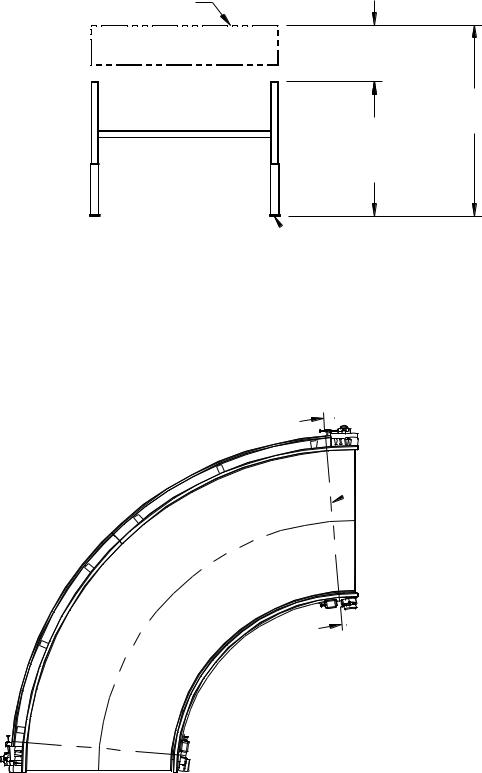
Top of Belt
266.7mm [10.5"] (Frame Depth + 1" Gap)
Required Top
Adjusted of Belt
Support
Height
 Floor Support Assembly
Illustration 2-1
2.Remove all hold-downs and lift the unit from the crate using a forklift, crane or other means, being careful not to damage the power turn. Attach the supports at the locations as shown in illustration 2-2, using the provided hardware.

 184mm [7.25"]
Support Locations From
 The Ends Of The Turn.

 57mm [2.25"]
NOTE: Equally space remaining supports between the mounted end supports. Outside radius distance between supports Is not to exceed 1524mm [60"].
 Belt Width
 Inside Radius

Illustration 2-2
Revision: E
Page 6 of 59
3.Properly position the power turn within the conveyor system and verify that the top of belt height provides a level transition or a downward cascade transition from the upstream conveyor and to the downstream conveyor. The top of belt height should also be level across the width and length of the power turn. Make any adjustments as needed.
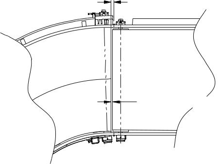
4.The curve should be centered between feeding and takeaway conveyor. If Transnorm System provides sideguards, we typically will allow 6.35mm(.25”) gap between outside radius bearing housing and adjoining conveyor frame to allow tightening and adjusting of the belt. This is accomplished by extending the sideguard 22.2mm(.88”) (at OR and IR) beyond the top face of the OR bearing housing. This normally results in a
22.2mm(.88”) gap between the belt on the curve and the frame on the adjoining conveyor. The gap between pulleys can be less than this if the pulley on the adjoining conveyor can extend beyond the conveyor frame. (See Illustration 2-3 and 2-4)
22.2m m [1.88"] |
|
Transnorm |
C onnecting |
Power Turn |
C onveyor |
|
6.35m m [.25"] ADJUSTM ENT |
Illustration 2-3
Revision: E
Page 7 of 59

Tra n s n o rm P o w e r Tu rn
1 2 .7 m m [ .5 0 "]
C o n n e c tin g
P o w e r Tu rn
4 4 .5 m m [ 1 .7 5 "] TO ALLO W F O R 6 .3 5 m m [ .2 5 "] AD J U S TM E N T O N E AC H C U R VE .
 2 2 .2 m m [ .8 8 "]
Illustration 2-4
5.Re-position the power turn as required and re-verify the top of belt height. Make any adjustments as needed. Attach the end flanges on the power turn side guard assemblies to the connecting conveyor side guard end flanges and then secure the floor support mount feet to the floor. All required installation hardware is to be provided by the installer.
6.To complete the installation of the power turn, all required system controls and electrical power would need to be installed. Only properly trained and certified electricians should perform this function in accordance to all applicable local and national standards.
Installation with Ceiling Hung Supports
Caution!
All power turns and related conveyor equipment must be properly supported individually. DO NOT support any conveyor equipment using side guard connections only.
1.Install the 3/4" all-thread rods (supplied by the customer) to provide support locations as shown in illustration 2-2.
NOTE: To assure room for maintenance work, the all-thread rods should be hung to allow a 4” clearance at all non-drive locations and a 10” clearance at the drive location.
Revision: E
Page 8 of 59
2.Thread (1) 3/4" jam nut onto each of the all-thread rods until it is above the approximate location of where the bottom edge of the power turn frame will be. The nuts should be positioned to avoid any interference with installation of the power turn.
3.Place the crated unit in an area clear of clutter with an ample workspace for setting up the power turn. Remove all hold-downs and lift the power turn to an appropriate working height. Install and secure the provided support mounting brackets in the locations as shown in illustration 2-2. Refer to illustration 2-5 to confirm proper orientation of the support mounting brackets.
4.Install the support tubes at each location using the 5/16” U-bolts around the pipe and up through the pre-drilled holes in the support mounting bracket with the appropriate hardware. (See illustration 2-5) Measure from the bottom edge of the power turn frame to the end of the tube allowing 6” for non-drive locations and 12” at the drive. Tighten the U-bolt hardware, securing the power turn to the pipe supports.
5.While lifting the power turn, insert the all-thread rods into the pre-drilled holes in the support pipes and position the power turn within the conveyor system. Verify that the top of belt height provides a level transition or a downward cascade transition from the upstream conveyor and to the downstream conveyor. The top of belt height should also be level across the width and length of the power turn. Make any adjustments as needed.
6.The curve should be centered between feeding and takeaway conveyor. If Transnorm System provides sideguards, we typically will allow 6.35mm(.25”) gap between outside radius bearing housing and adjoining conveyor frame to allow tightening and adjusting of the belt. This is accomplished by extending the sideguard 22.2mm(.88”) (at OR and IR) beyond the top face of the OR bearing housing. This normally results in a 22.2mm(.88”) gap between the belt on the curve and the frame on the adjoining conveyor. The gap between pulleys can be less than this if the pulley on the adjoining conveyor can extend beyond the conveyor frame. (See Illustration 2- 3 and 2-4)
7.Thread (1) 3/4" jam nut onto each of the all-thread rods and tighten the nuts against the support pipe. Add an additional jam nut to each of the all-thread rods and tighten until the jam nuts lock against each other. Tighten the previously installed jam nuts (above the pipe) down until they lock firmly against the pipe.
8.Re-check the elevation and proper leveling of the power turn. Re-position the power turn as required and re-verify the top of belt height. Make any adjustments as needed. Attach the end flanges on the power turn side guard assemblies to the connecting conveyor side guard end flanges. All required installation hardware for this step is to be provided by the installer.
Revision: E
Page 9 of 59

9.To complete the installation of the power turn, all required system controls and electrical power would need to be installed. Only properly trained and certified electricians should perform this function in accordance to all applicable local and national standards.
Illustration 2-5
SECTION III
INITIAL START-UP
Attention!
Read and understand all instructions within this section prior to beginning the initial start-up of the power turn.
Caution!
The main disconnect switch of the system must be turned off and locked out according to all applicable local and national standards.
1.Check the installation position: Check the top of belt heights between the TS1500/140 power turn and the connecting conveyors. Verify that the power turn is also level in the width and length directions.
2.Factory Belt Tension: Transnorm marks factory adjustment location with scribed lines on outer bearing housings showing factory location of bearing.
(See Figure 3-1)
Revision: E
Page 10 of 59

Figure 3-1
Inner housings are marked for factory position on shaft of trommelager assembly.
(See Figure 3-2)
Figure 3-2
Revision: E
Page 11 of 59

3.Cleaning: The power turn must be free of dirt and/or debris. All foreign elements must be removed (especially from the belt and pulleys).
4.Check the side guarding: The side guarding must be mounted so that the guards cannot interfere with the running of the belt or the flow of material.
5.Check the drive motor assembly: To inspect the drive assembly, remove the drive cover and check the condition of the drive components, verifying that everything is in the correct position. Replace the drive cover. Locate the vent plug on the reducer and insure that it is in an upward position.
Caution!
The electrical lock out is to be removed to complete steps 5 & 6. Extreme caution must be taken to ensure the safety of the maintenance personnel.
6.Start running the power turn: First, check the running direction of the belt by jogging the motor. The direction of flow should always be towards the drive location as the power turn pulls the belt. If the power turn pushes the belt, the flow direction is not correct and 2 poles of the electrical connections at the motor must be reversed. Turn off the power prior to changing any of the motor lead connections.
7.Check the running of the belt: The power turn should run smoothly and quietly without noises and with a minimum of belt waving (bumps or ripples, not to exceed 10mm in height). Excessive waving is an indication of improper belt tracking and should be adjusted according to Section IX – Belt Tracking.
Revision: E
Page 12 of 59

SECTION IV
OPERATIONAL TROUBLESHOOTING
The following troubleshooting chart refers to possible problems that may occur in the operation of the Transnorm System Inc. power turn. If a problem exists outside the scope of this troubleshooting guide, contact Transnorm System Inc. customer service department for additional assistance.
PROBLEM |
PROBABLE CAUSE |
POSSIBLE SOLUTION |
Power turn does not run |
Open circuit |
Close circuit by professional |
|
|
|
|
Motor defective |
Replace motor |
|
|
|
Power turn does not |
|
|
operate with |
|
|
Motor running |
Drive belt slipping |
Tighten drive belt |
|
|
|
Rough running belt |
Belt not tensioned |
Tension belt |
|
|
|
|
Beading defective |
Replace belt |
|
|
|
|
Belt blocked by foreign |
|
|
object |
Remove foreign object |
|
|
|
Beading comes out of |
|
|
holders |
Incorrect belt adjustment |
Correct adjustment |
|
|
|
|
Belt blocked by foreign |
|
|
object |
Remove foreign object |
|
|
|
Noise in beading holders |
Bearing damaged |
Replace holder |
|
|
|
|
Holder damaged |
Replace holder |
Revision: E
Page 13 of 59

SECTION V
PREVENTIVE MAINTENANCE
The following points of the maintenance plan have to be checked on regular intervals. The listed intervals are for one-shift-operations under normal conditions as described within the
Operating Conditions of Section I – General Description.
TASK |
PERIOD |
COMMENT |
Clean belt, check belt |
Quarterly |
Use 409 cleaner (diluted with |
and beading for wear or |
|
water 50/50) and paper |
damage. |
|
towels to clean the belt. |
|
|
Note: Non-textured belts only. |
|
|
|
|
|
|
Check belt tension and |
Quarterly |
Adjust as necessary per |
belt run. |
|
Section IX - Belt Tracking. |
|
|
|
Check bearings in the |
Every 6 months for the |
Replace as needed. |
holders for noise. |
first year, monthly after |
|
|
that. |
|
|
|
|
Check inside radius and |
Every 6 months for the |
Replace as needed. |
outside radius bearings |
first year, monthly after |
|
for noise. |
that. |
|
|
|
|
|
|
|
Checking drive pulley for |
Quarterly |
Replace as needed. |
damage |
|
|
|
|
|
Check gear motor or |
Quarterly |
Replace or adjust as needed. |
motor/reducer for noise. |
|
|
|
|
|
Check oil in gear motor or |
Per manufacturer's |
Check manufacturer's |
motor/reducer. |
specifications. |
specifications or contact |
|
|
Transnorm System Inc. |
|
|
|
|
|
|
Chain / V-belt drive. |
Quarterly |
Adjust tension and/or |
|
|
lubricate as necessary. |
Revision: E
Page 14 of 59

SECTION VI
SIDE GUARD REMOVAL
Attention!
Read and understand all instructions within this section prior to beginning any operation, installation, service or maintenance of the power turn.
Caution!
Before installation, service or maintenance, the main disconnect switch of the system must be turned off and locked out according to all applicable local and national standards.
In general, most power turn orders will have side guard assemblies along the inside radius and the outside radius of the power turn assembly. The inside radius side guard is bolted directly through the deck board along the inside radius. The outside radius side guard is welded to the top shroud and the side guard assembly is then bolted to the top of the upper belt bead holders. On some power turns, the outside radius side guard assembly may be made in multiple pieces and will have splice angles between each of the sections. Attached to the outside of the in-feed and discharge ends of the side guard assemblies are flanges for connecting the power turn side guards to the connecting conveyor side guards.
Prior to any maintenance work such as changing the belt, the drive pulley, the tail pulley or any of the belt bead holders, the side guard assemblies, the perforated guards and the outer end guards will need to be removed first. After completion of the required maintenance work, reinstall the side guard assemblies, the perforated guards and the outer end guards onto the power turn.
Caution!
All power turns and related conveyor equipment must be properly supported individually.
DO NOT support any conveyor equipment using side guard connections only.
To complete the procedure within this section, the following tools will be required:
Wrenches - 13mm & 17mm
Phillips Head Screwdriver
Caution!
The use of (2) maintenance personnel should be considered for this procedure when the angle of the power turn assembly exceeds 30 degrees.
1.Remove the hardware from the butt flanges at the in-feed and discharge ends of the side guard assemblies.
Revision: E
Page 15 of 59

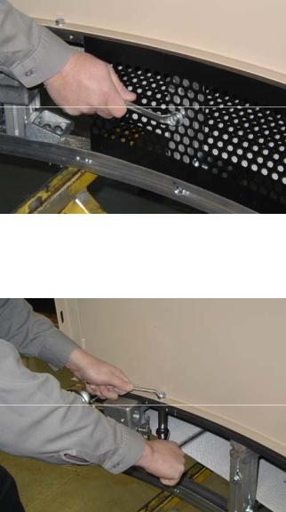
2.If the outside radius side guard is made in multiple sections, the hardware at each splice will need to be removed using the 13mm wrench.
3.Remove the hardware from the outer end guards (LH and RH) and the outer perforated guard using the 13mm wrench.
Revision: E
Page 16 of 59

4.Remove the hardware along the top shroud using the 13mm wrench. Next, remove the hardware from the outside radius housing using the 17mm wrench. Once the attachment hardware has been removed, take the outside radius side guard assembly off the power turn.
Revision: E
Page 17 of 59
5.Remove the Phillips head screws at the top of the inner end guards (universal). Next remove the hardware from the inner end guard and the inner perforated guard using the
13mm wrench.
6.Remove the hardware along the deck board of the inside radius side guard. Once all of the attachment hardware has been removed, take the inside radius side guard assembly off of the power turn.
7.Upon completion of the maintenance work, reinstall the side guard assemblies in the reverse order in which they were removed. Verify that there is no interference with the belt from the side guard assemblies after they have been installed. Make any adjustments as required.
Revision: E
Page 18 of 59
 Loading...