

Transmille EA3012A Operation Manual
www. transmille.com

Version 4.00
May 2018
All product names are trademarks of their respective c ompanies
EA3012A
Transconductance Amplifier
Operation Manual

EA3012A TRANSCONDUCTANCE AMPLIFIER
OPERATION MANUAL
Transmille Ltd. Page 2
Guarantee and service
Transmille Ltd. guarantees this instrument to be free from defects under
normal use and service for a period of 1 years from purchase. This guarantee
applies only to the original purchaser and does not cover fuses, or any
instrument which, in Transmille’s opinion, has been modified, m i sused or
subjected to abnormal handling or operating condi ti ons.
Transmille’s obligation under this guarantee is limited to replacement or
repair of an instrument which is returned to Transmille within the warranty
period. If Transmille determines that the fault has been caused by the
purchaser, Transmille will contact the purchaser before proceeding with any
repair.
To obtain repair under this guarantee the purchaser must send the instrument
in its original packaging (carr iage prepaid) and a description of the fault to
Transmille at the address shown below. The instrument will be repaired at the
factory and returned to the purchaser, carriage prepaid.
Note :
TRANSMILLE ASSUMES NO RESPONSIBILITY FOR DAMAGE IN TRANSIT
THIS GUARANTEE IS THE PURCHASER’S SOLE AND EXCLUSIVE
GUARANTEE AND IS IN LEIU OF ANY OTHER GUARANTEE, EXPRESSED OR
IMPLIED. TRANSMILLE SHALL NOT BE LIABLE FOR ANY INCIDENTAL,
INDIRECT, SPECIAL OR CONSEQUENTIAL DAMAGES OR LOSS.
Transmille Ltd.
Unit 4, Select Business Centre
Lodge Road
Staplehurst
Kent
TN12 0QW
United Kingdom
Tel : +44 0 1580 890700
Fax : +44 0 1580 890711
EMail : sales@transmille.com
Web : www.transmille.com

EA3012A TRANSCONDUCTANCE AMPLIFIER
OPERATION MANUAL
Transmille Ltd. Page 3
TABLE OF CONTENTS
GUARANTEE AND SERVICE .......................................................................................................................... 2
OPERATIONAL NOTE ..................................................................................................................................... 4
EA3012A TRANSCONDUCTANCE AMPLIFIER ......................................................................................... 5
MAIN FEATURES ................................................................................................................................................ 5
DESIGN NOTES .................................................................................................................................................. 6
FEATURES .......................................................................................................................................................... 6
FRONT PANEL LED INDICATORS ....................................................................................................................... 7
REAR PANEL CONNECTIONS .............................................................................................................................. 8
OPERATING NOTES ............................................................................................................................................ 8
USING THE EA3012A FROM THE 3000A FRONT PANEL* ................................................................................ 11
USING T HE EA019 HIGH CURRENT COIL WITH 3000A FRONT PANEL CONTROL ............................................. 12
USING THE EA3012A FROM THE 4000 SERIES FRONT PANEL* ....................................................................... 14
USING THE EA019 HIGH CURRENT COIL WITH 4000 SERIES FRONT PANEL CONTROL..................................... 15
USING THE EA3012A WITH THE VIRTUAL FRONT PANEL SOFTWARE ............................................................. 16
Installing the Software ............................................................................................................................... 16
Selecting a COM Port ................................................................................................................................ 16
Operation of the Virtual Front Panel ........................................................................................................ 17
Functions : Setting a Current Output ........................................................................................................ 17
Functions : AC Output ............................................................................................................................... 18
Auto Output mode ...................................................................................................................................... 18
High Current Operation............................................................................................................................. 18
Output Error Detection .............................................................................................................................. 19
SPECIFICATIONS ............................................................................................................................................... 20
CARE & MAINTENANCE ................................................................................................................................... 21
Cleaning the EA3012A ............................................................................................................................... 21
Handling Precautions ................................................................................................................................ 21
Servicing Information ................................................................................................................................ 21
Recalibration ............................................................................................................................................. 21
SUPPORT .......................................................................................................................................................... 22
EA3012A TRANSCONDUCTANCE AMPLIFIER
OPERATION MANUAL
Transmille Ltd. Page 4
OPERATIONAL NOTE
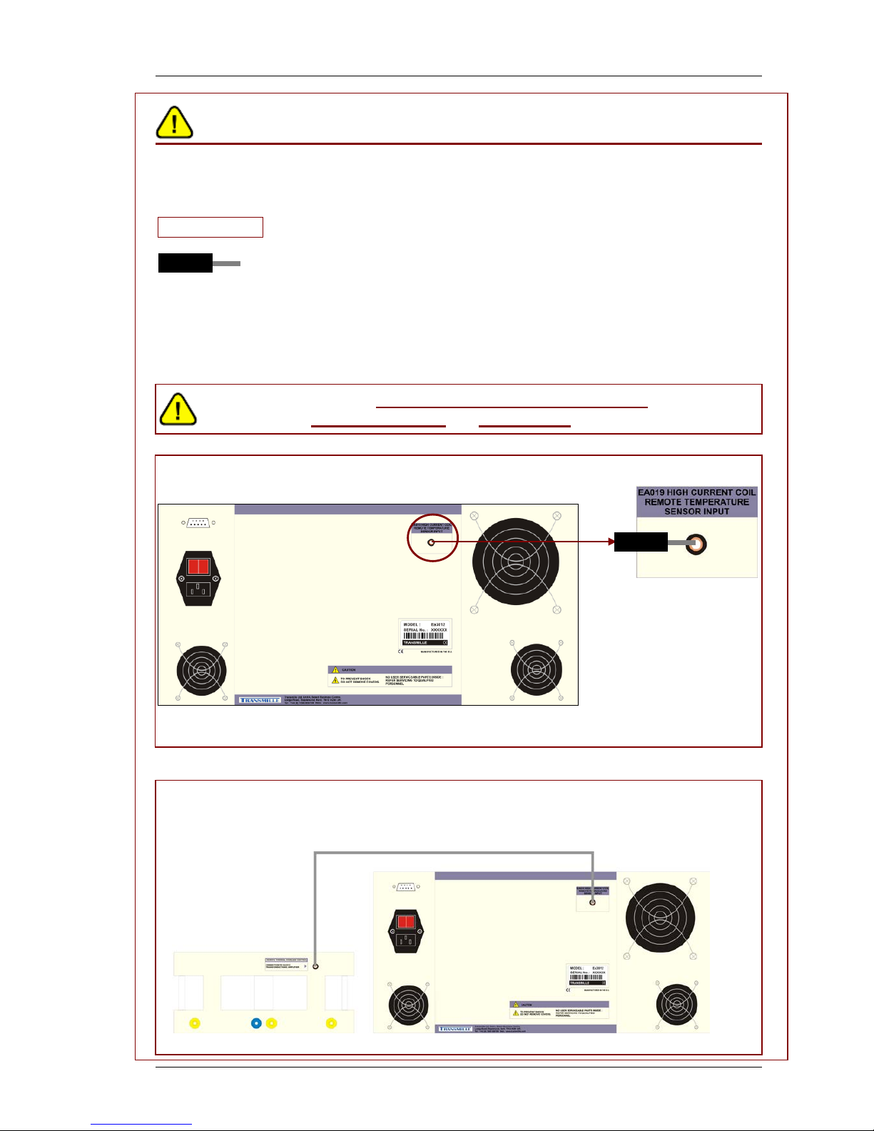
The amplifier has a remote cut-out connection on the rear panel.
When using the amplifier direc tly the output must be enabled by inserting the
Shorting Link supplied into the rear panel socket s hown below.
SHORTING LINK
When using the optional EA019 High Current clamp coil c onnect the amplifier
to the thermal trip in the coil using the lea d supplied. The thermal cut-out in
the coil will turn off the amplifi er output to prevent damage to the coil.
NOTE : FOR SAFETY NO OUTPUTS WILL BE AVAILABLE UNTIL
EITHER THE SHORTING PLUG OR EA019 COIL ARE CONNECTED
Example – without coil in use :
Example – with Coil in use
EA3012A TRANSCONDUCTANCE AMPLIFIER
OPERATION MANUAL
Transmille Ltd. Page 5
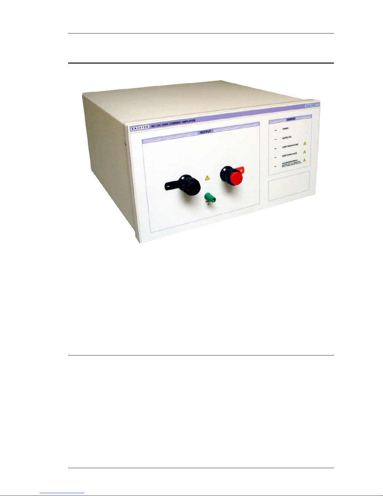
EA3012A Transconductance Amplifier
The EA3012A is a powerful linear transconductance amplifier designed exclusively
for use with the 3000 Series calibrators which provides a cost effective solution to
calibrating high currents instruments.
Connecting to the 3000 Series calibrator using the feature connector, the EA3012A
extends the output current range to 100A DC / 75A AC - higher currents are
available by paralleling EA3012A’s as required to give the current output needed.
Main Features
Controlled by Virtual Front Panel Software (Suppli ed) or ProCal (option)
Stackable for Higher Currents
Low Noise Linear MOSFE T Technology
Up to 100A DC • 70A AC Output
Calibration of up to 2000A Clamp Meters Using 50 Turn Coil*
Ideal For Calibrating High Power Current Shunts & Current Meters
* Requires EA019 enhanced clamp coil adapter wi th i n teg rated temperature sensor above 1500A
EA3012A TRANSCONDUCTANCE AMPLIFIER
OPERATION MANUAL
Transmille Ltd. Page 6
Design Notes
Use of linear technology throughout gives a very low noise output completely free
from any switching spikes.
The latest in high power MOSFET design ensures reliable and stable operation
even into inductive loads.
Long term accuracy is assured by using precision foil resistors and a custom
manufactured internal shunt.
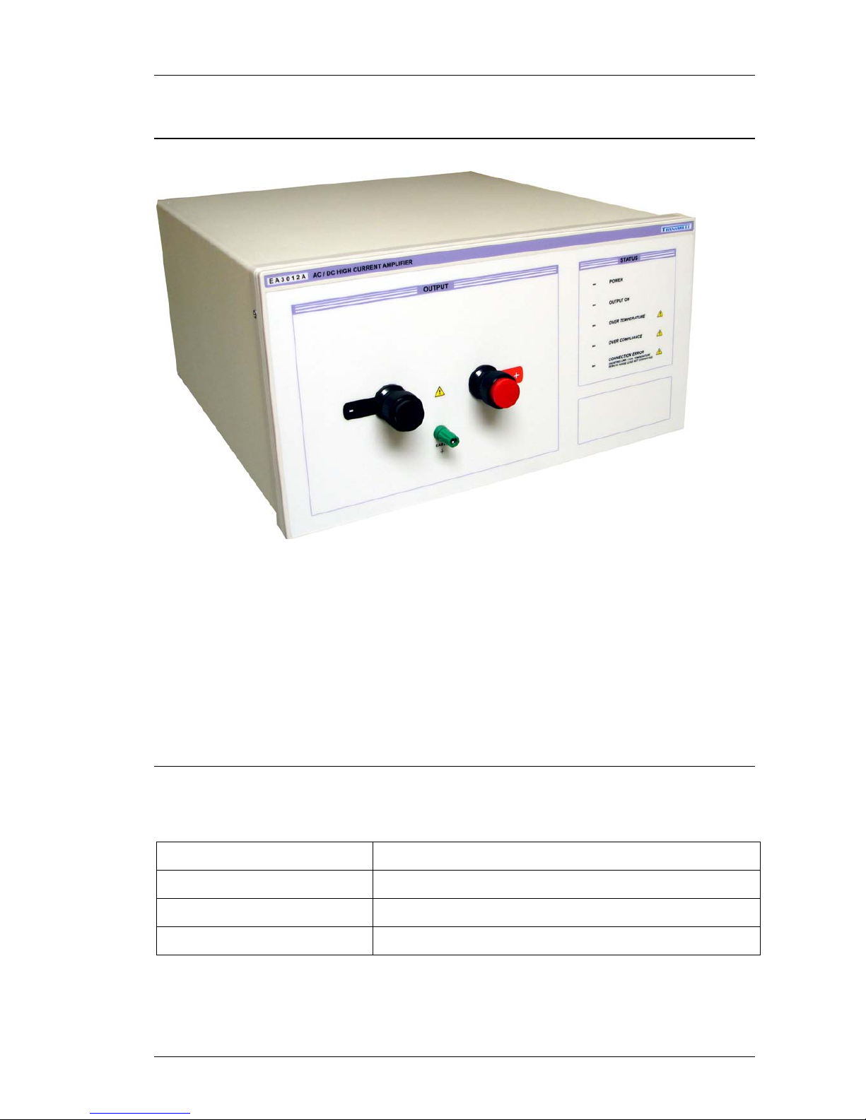
Features
Functions of the terminal post connections :
EA3012A Terminal Post
Function
CURRENT HI
Positive output to UUT
CURRENT LO
Negative output to UUT
EARTH
Connected to the case
EA3012A TRANSCONDUCTANCE AMPLIFIER
OPERATION MANUAL
Transmille Ltd. Page 7
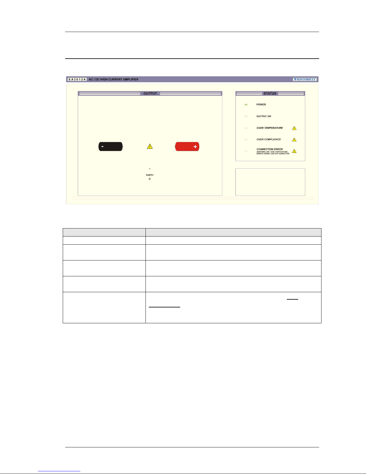
Front Panel LED Indicators
Indicator
Description
POWER
Power connected and instrument switched on
OUTPUT ON
Instrument output switch on – current actively being
output from front panel terminals
OVER TEMPERATURE
Temperature of internal heatsinks exceeds operating
limits – output switched off to allow cooling of heatsinks
OVER COMPLIANCE
Compliance voltage exceeds operating parameters –
ensure correct connection to front panel terminals
CONNECTION ERROR
SHORTING LINK / COIL
TEMPERATURE REMOTE SENSE
LEAD NOT CONNECTED
The shorting link supplied with the amplifier is not
connected to the rear panel (no coil in use) or the
remote temperature sense lead is not connected from
the EA019 High Current Coil (option) to the amplifier.
 Loading...