

Page 1

EA3023
PSU CALIBRATION ADAPTER
Ü
OPERATION MANUAL
Page 2

EA3023
3A POWER SUPPLY CALIBRATION ADAPTER
Operation Manual
Version 1.00
April 2007
All product names are trademarks of their respective companies
Page 3

EA3023 3A POWER SUPPLY CALIBRATION ADAPTER
OPERATION MANUAL
Guarantee and service
Transmille Ltd. guarantees this instrument to be free from defects under
normal use and service for a period of 1 years from purchase. This guarantee
applies only to the original purchaser and does not cover fuses, or any
instrument which, in Transmille’s opinion, has been modified, misused or
subjected to abnormal handling or operating conditions.
Transmille’s obligation under this guarantee is limited to replacement or
repair of an instrument which is returned to Transmille within the warranty
period. If Transmille determines that the fault has been caused by the
purchaser, Transmille will contact the purchaser before proceeding with any
repair.
To obtain repair under this guarantee the purchaser must send the instrument
in its original packaging (carriage prepaid) and a description of the fault to
Transmille at the address shown below. The instrument will be repaired at the
factory and returned to the purchaser, carriage prepaid.
Note :
TRANSMILLE ASSUMES NO RESPONSIBILITY FOR DAMAGE IN TRANSIT
THIS GUARANTEE IS THE PURCHASER’S SOLE AND EXCLUSIVE
GUARANTEE AND IS IN LEIU OF ANY OTHER GUARANTEE, EXPRESSED OR
IMPLIED. TRANSMILLE SHALL NOT BE LIABLE FOR ANY INCIDENTAL,
INDIRECT, SPECIAL OR CONSEQUENTIAL DAMAGES OR LOSS.
Transmille Ltd.
Unit 4, Select Business Centre
Lodge Road
Staplehurst
Kent
TN12 0QW
United Kingdom
Tel : +44 0 1580 890700
Fax : +44 0 1580 890711
EMail : [email protected]
Web : www.transmille.com
Transmille Ltd. Page 2
Page 4

EA3023 3A POWER SUPPLY CALIBRATION ADAPTER
OPERATION MANUAL
TABLE OF CONTENTS
GUARANTEE AND SERVICE...............................................................................................................2
EA3023 POWER SUPPLY CALIBRATION ADAPTER........................................................................4
MAIN FEATURES...................................................................................................................................4
DESIGN NOTES.....................................................................................................................................5
FEATURES............................................................................................................................................5
CONNECTIONS......................................................................................................................................6
OPERATING NOTES...............................................................................................................................6
USING THE EA3023 WITH THE VIRTUAL FRONT PANEL SOFTWARE........................................................8
Installing the Software.................................................................................................................8
Selecting a COM Port ..................................................................................................................8
Operation of the Virtual Front Panel..........................................................................................9
Functions : Measuring A Voltage...............................................................................................9
Functions : Setting A Current Load.........................................................................................10
Functions : Output Resistance Measurement........................................................................10
CARE & MAINTENANCE.......................................................................................................................11
Cleaning the EA3023 .................................................................................................................11
Handling Precautions................................................................................................................11
Servicing Information................................................................................................................11
Appendix A : Specifications
Transmille Ltd. Page 3
Page 5
EA3023 3A POWER SUPPLY CALIBRATION ADAPTER
OPERATION MANUAL
EA3023 Power Supply Calibration
Adapter
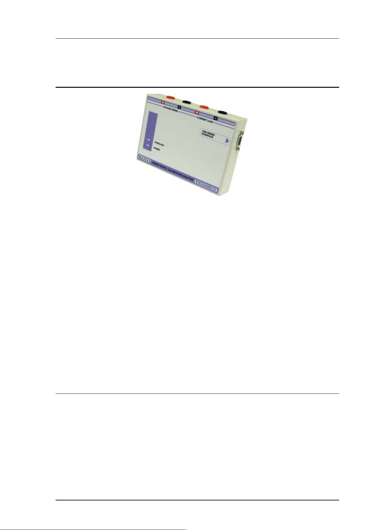
The EA3023 provides an easy to use solution for the calibration of power supplies
up to 3A. The output from the calibrator is converted by the PSU adapter into a
precision current load and the supply output voltage is measured by using the
calibrators internal high accuracy A/D converter.
The operation is controlled using a PC running either the Virtual front panel program
or ProCal software. The software sends commands to the calibrator to set the output
or read back the voltage which is displayed on the computer
Traditional techniques of using high current low value load resistors and current
shunts can result in unstable/inaccurate readings even with small voltage
fluctuations from the power supply or variations in connection and lead resistance.
The manual nature of this method is both time consuming and prone to accidental
damage of the load resistor and measurement equipment.
Main Features
Measure Output Voltage to 100V
Active Current Load to 4A
Measures Output Resistance
Applications Include Battery & UPS Testing
Connects to Adapter Interface on 3000 Series Calibrator
Used with Virtual Front Panel or ProCal Software
Transmille Ltd. Page 4
Page 6
EA3023 3A POWER SUPPLY CALIBRATION ADAPTER
OPERATION MANUAL
Design Notes
Provides an accurate, stable electronic load regardless of the power supply
output voltage and lead / connection resistances.
Removes the need for high power load resistors of appropriate values.
Allows automation for more efficient calibration
Features
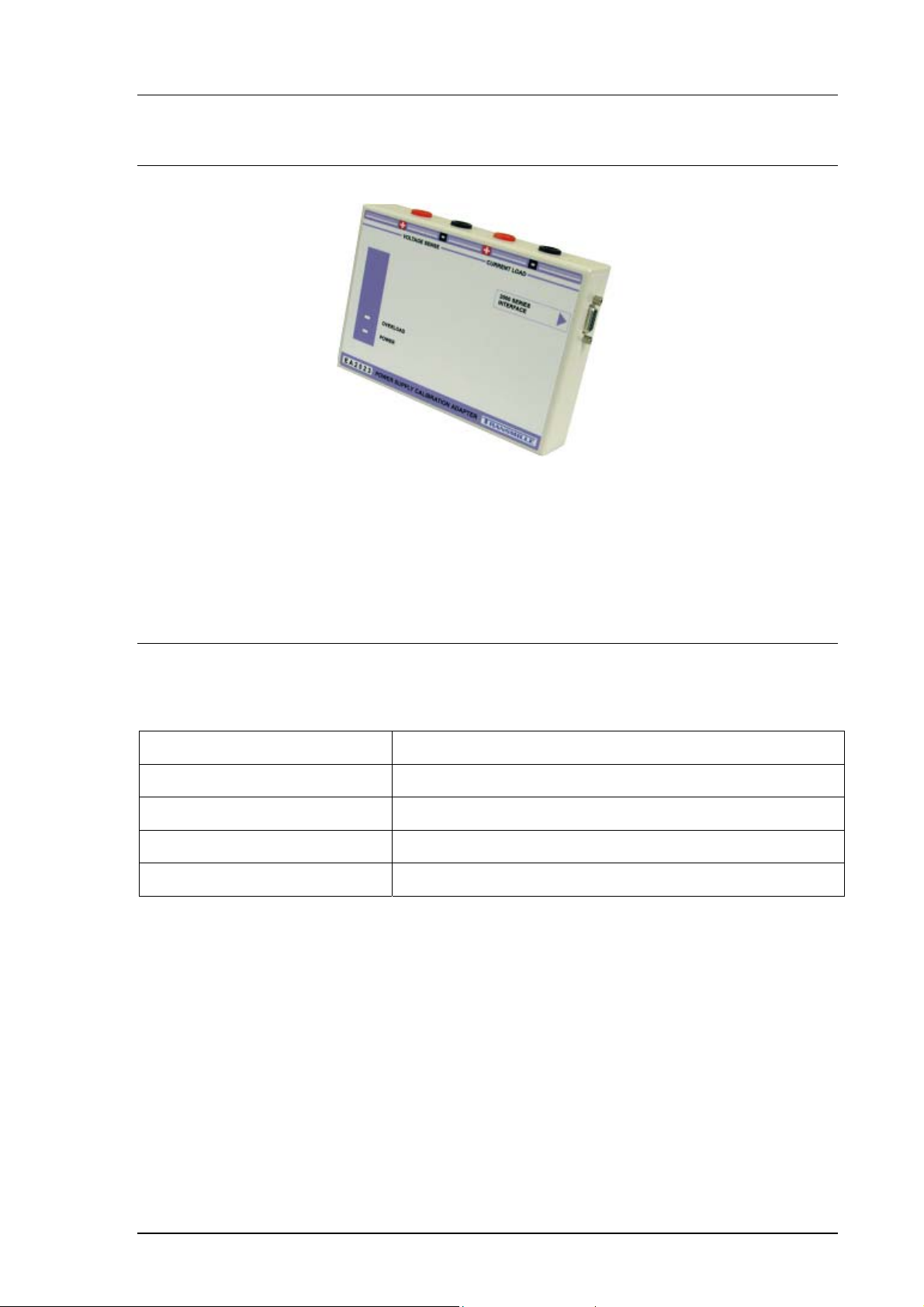
Functions of the terminal connections :
EA3023 Terminal Function
VOLTAGE HI Positive voltage input from UUT
VOLTAGE LO Negative voltage input from UUT
CURRENT HI Positive sense input from UUT
CURRENT LO Negative sense input from UUT
Transmille Ltd. Page 5
Page 7
EA3023 3A POWER SUPPLY CALIBRATION ADAPTER
OPERATION MANUAL
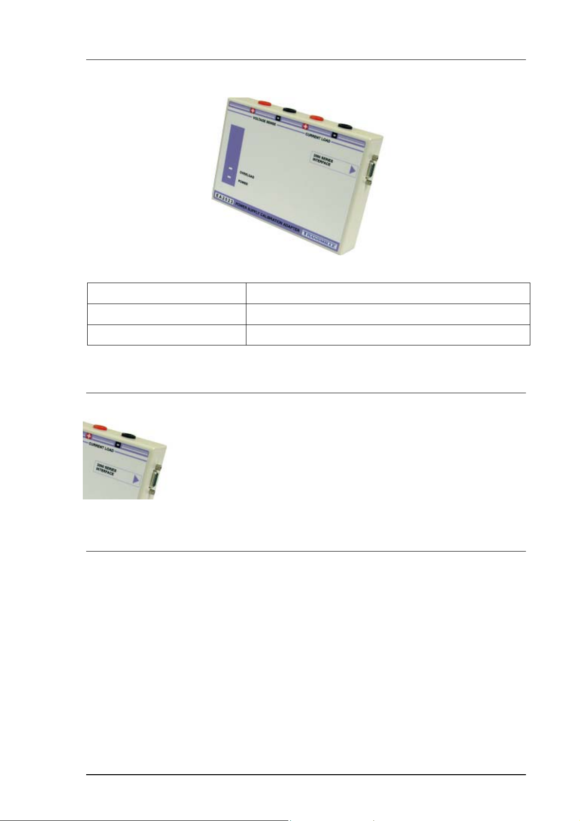
Label Reference Information
Model Number Model number reference for product
Serial Number Unique serial number for product
Connections
Connection to the 3000 Series adapter interface is provided
via a 9-Pin D-Type connection located on the side of the
adapter
Operating Notes
This section details operational and environmental considerations for the EA3023
PSU Adapter. Follow these instructions when operating or storing the PSU Adapter.
Transmille Ltd. Page 6
Page 8
EA3023 3A POWER SUPPLY CALIBRATION ADAPTER
OPERATION MANUAL
Connection Recommendations
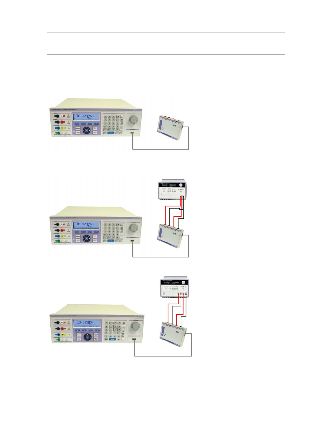
To connect the EA3023 PSU Adapter to the 3000 Series multi product calibrator,
use the supplied adapter interface cable (9-Pin Male to 9-Pin female straight through
lead) :
To use the EA3023 PSU Adapter, connect the positive and negative
outputs to the unit under test as shown below :
Fig. 1 : 2 Terminal Power Supply Connection Example
Fig. 2 : 4 Terminal Power Supply Connection Example
Transmille Ltd. Page 7
Page 9
EA3023 3A POWER SUPPLY CALIBRATION ADAPTER
OPERATION MANUAL
Using the EA3023 with the
Virtual Front Panel Software
Installing the Software
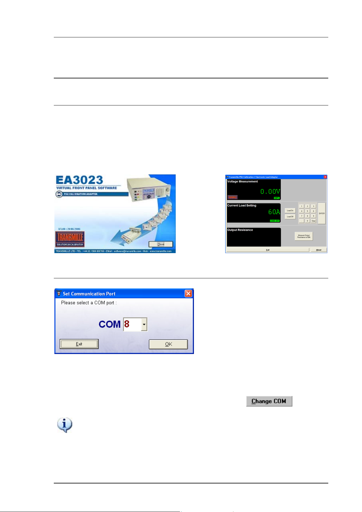
Insert the CD supplied with the EA3023 PSU Adapter – this should auto run. If it
does not auto run, click START -> Run then run x:\Setup.exe where x is the drive
letter of your CD drive.
Once installation is complete choose START -> ALL PROGRAMS -> EA3023 PSU
Adapter to run the virtual front panel
Selecting a COM Port
On starting the virtual front panel for the first time, a COM port selection screen will
be displayed. Click on the COM port which is connected to your 3000 Series
calibrator to continue.
A different COM port can be selected at any time using the button.
If you are using a laptop to connect to the calibrator, the COM port will
usually be COM 1. A desktop computer will usually be COM 2
Transmille Ltd. Page 8
Page 10
EA3023 3A POWER SUPPLY CALIBRATION ADAPTER
OPERATION MANUAL
Operation of the Virtual Front Panel
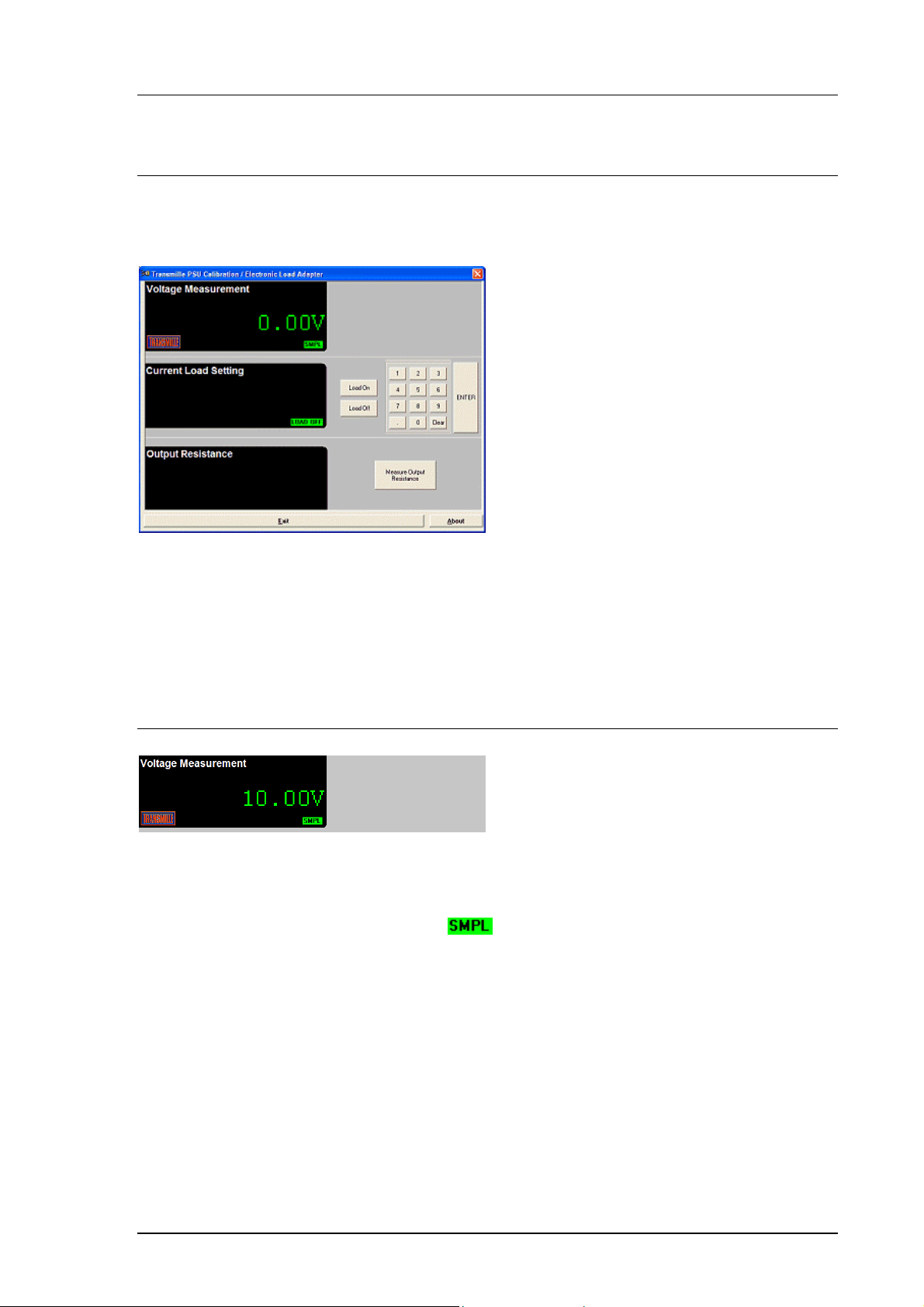
Once the correct COM port is selected, the calibrator will be detected, and the main
screen displayed :
The main screen comprises of three sections :
• Voltage measurement (from power supply)
• Current Load setting
• Output Resistance
Functions : Measuring A Voltage
Connect the power supply adapter to the voltage and current terminals.
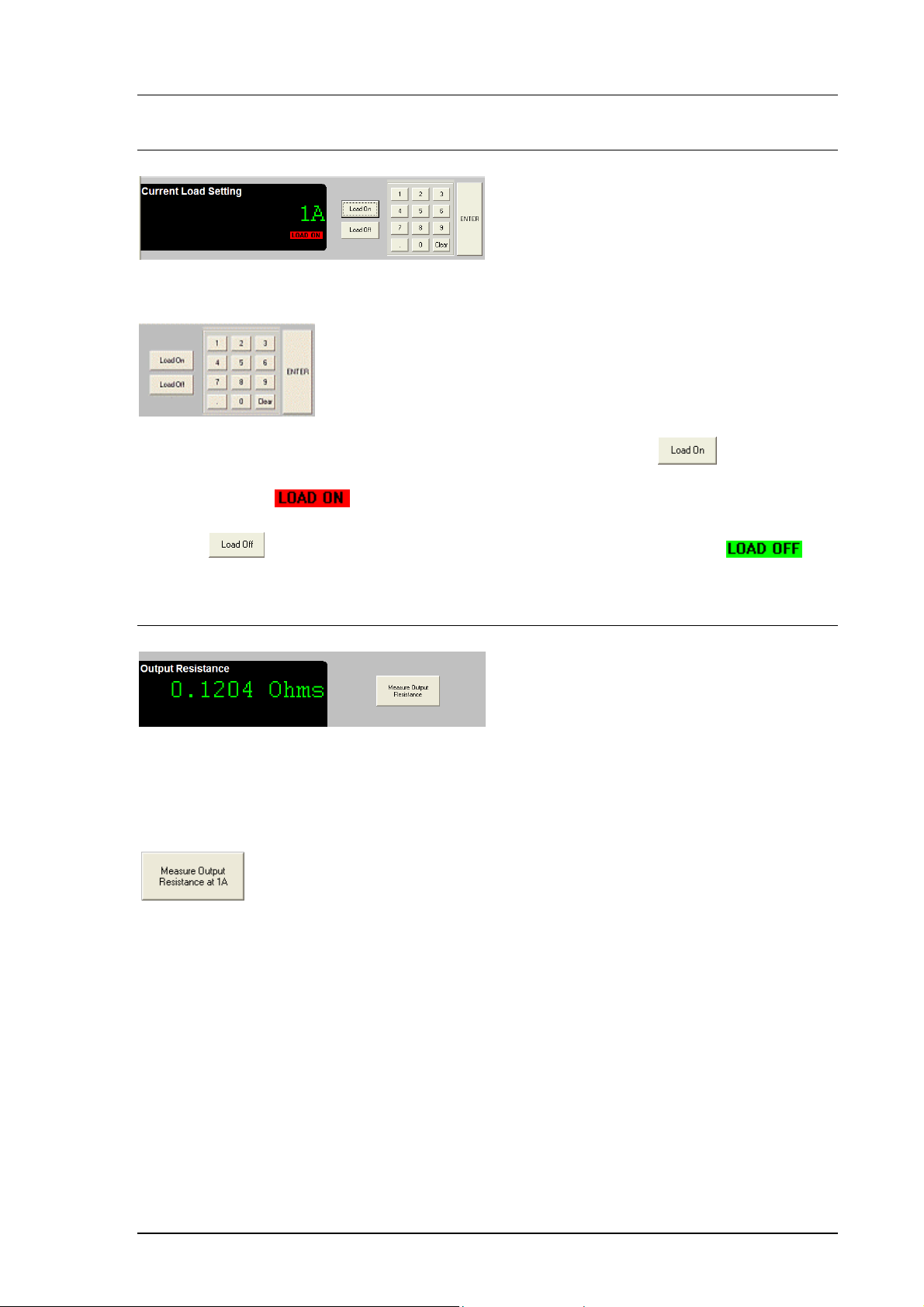
Set an output voltage from the power supply and this will be displayed in the virtual
front panel voltage display section. A indicator will flash periodically to indicate
a measurement sample is being made.
Transmille Ltd. Page 9
Page 11
EA3023 3A POWER SUPPLY CALIBRATION ADAPTER
OPERATION MANUAL
Functions : Setting A Current Load
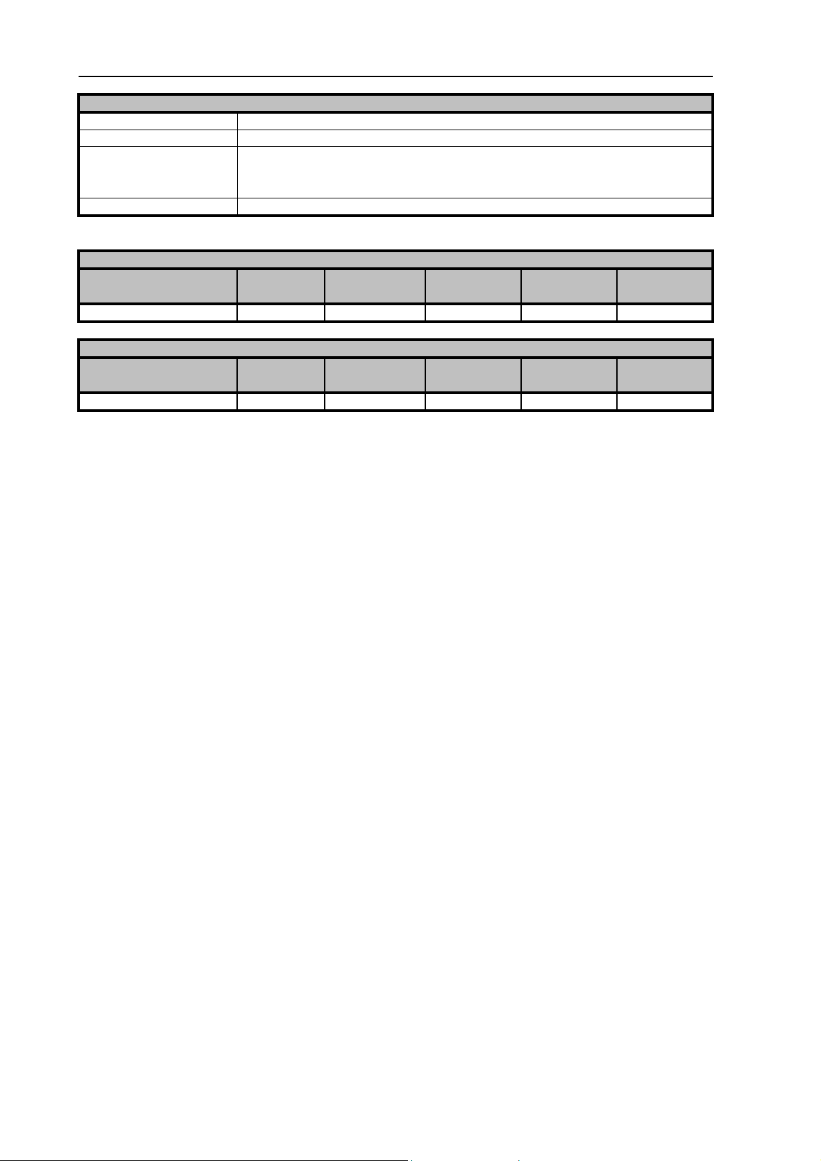
Use the on screen keyboard to set the required current load :
Press the ENTER button to preset the current load, then press
to apply the
setting– the applied load will be displayed on the power supply current meter – the
VFP will display
Use the button to turn off the current load – the VFP will display
Functions : Output Resistance Measurement
The output resistance measurement function uses the electronic current load to
measure the voltage drop on-load and off-load. Using a calculation the output
resistance can then be displayed.
Press the output resistance measurement button - the virtual front
panel will display ‘Calculating…’ while the load is turned on, then off in
a controlled sequence to determine the voltage drop and calculating
the output resistance.
If no voltage drop is detected a message will be displayed to indicate the resistance
could not be determined.
Transmille Ltd. Page 10
Page 12

EA3023 3A POWER SUPPLY CALIBRATION ADAPTER
OPERATION MANUAL
Care & Maintenance
The only maintenance instructions for the EA3023 PSU Adapter is periodic cleaning.
See below for details on the cleaning procedure and precautions for handling.
Cleaning the EA3023
To keep the external enclosure of the EA3023 in good condition, clean the outer
case with a soft cloth. Do not use any liquids in cleaning the enclosure – removal of
surface dust is all that is recommended.
CAUTION
Do not use cleaning fluids or solvents for cleaning as these may damage the
enclosure and affect the plastic materials used in the PSU Adapter.
Handling Precautions
The EA3023 is designed for mechanical stability, but should not be subjected to
excessive shock or be dropped. Transportation is recommended using the original
packaging with avoidance of extreme changes of temperature.
Servicing Information
The EA3023 is provided certified from the factory, and uses high precision nonadjustable shunts and are not user repairable. If the instrument is damaged it should
be returned to the factory for repair and recalibration.
Transmille Ltd. Page 11
Page 13

EA3023 3A POWER SUPPLY CALIBRATION ADAPTER
OPERATION MANUAL
Power Supply Calibration Adapter
EA3023
Appendix A
Specifications
Transmille Ltd. Page 12
Page 14
EA3023 Power Supply Calibration Adapter Specifications
r
y
y
A
General Specifications
Adaptor connection Connects to male 'D' type adapter interface on 3000 Series front panel
Indicators Incorporates 1x Power indicator LED : 1 x Overload indicator LED
Connections 1 x 9 way male 'D' type connector
2x Voltage input 4mm terminals (Red & Black)
2x Current load 4mm terminals (Red & Black)
Connection to Calibrato
Via supplied 9 Way male to female serial lead (straight through connection)
DC Voltage Measurement Accurac
Range Resolution 90 Day Rel. 180 Day Rel. 1 Year Rel. 2 Year Rel.
% ±mV % ±mV % ±mV % ±mV
0 to 63 Volts 0.01V 0.016 ± 20 0.016 ± 20 0.02 ± 20 0.028 ± 20
DC Current Load Accurac
Range Resolution 90 Day Rel. 180 Day Rel. 1 Year Rel. 2 Year Rel.
% ±mA % ±mA % ±mA % ±mA
0 to 3 Amps 0.01
Specifications apply between 17°C and 27°C.
Outside this range an allowance of 0.18 x 1 Year Spec. per °C should be added.
Due to continuous development specifications may be subject to change.
0.040 ± 1.0 0.045 ± 1.0 0.05 ± 1 0.070 ± 1.0
2000 Series Options Extended Specifications : Power Supply Calibration Option V2.00
 Loading...