

Transmille 8700 Operation Manual

Page 1
8700 Operation Manual
TRANSMILLE 8700
OPERATION MANUAL
FREQUENCY SOURCE / MEASURE
GPS STANDARD

Page 2
8700 Operation Manual
Warranty
Transmille guarantees this product to be free from defects in material and workmanship under
normal user for a period of one (1) year from the date of shipment. This warranty does NOT cover any
required re-calibration/adjustment or standard maintenance actions. This warranty extends only to the
original end purchaser and does not apply to fuses, batteries, external cables or to the product if it has
been modified, misused, altered or has been subjected to mishandling or misuse.
Transmille’s obligation to warranty is limited to repair or replace the product after return to
an authorized Transmille service centre within the warranty period and is subject to Transmille’s
investigation determining that the fault is not caused by misuse, alteration or through mishandling.
If failure occurs, send the product via pre-paid freight, to the service centre as informed by
Transmille with a description of the fault only after receiving confirmation from Transmille. At
Transmille’s option, either repairs will be performed or a replacement unit of similar condition and
age will be provided.
Transmille will return the product to the end customer or local distributor via pre-paid freight
(with exception of any customs clearance fees).
Transmille accept no responsibility for damage during return shipping for warranty service.

Page 3
8700 Operation Manual
Contents
8700 General Specifications ....4
8700 Declaration Of Conformity 5
8700 Frequency Source/Measure GPS Standard 6
Introduction ........................................................6
Main Features ....................................................6
Preparing the Unit for Use .......7
Initial Inspection .................................................7
Positioning the Standard ....................................7
Positioning the Antenna ...................................... 7
Rear Panel Connections ....................................8
Setting and checking the line voltage .................8
Powering up the Instrument ................................9
RS232 Interface .................................................9
USB Interface.....................................................9
Ethernet Interface ..............................................10
GPIB Interface ...................................................10
Front Panel Connections .........11
Output Connectors .............................................11
Input Connectors ................................................11
Input Characteristics ..........................................11
Operation ................................12
Front Panel Controls ..........................................12
GPS Status Display ............................................13
Source Functions .....................14
GPS FREQUENCY [10MHz REFERENCE].........14
GPS FREQUENCY [DIVIDER MODE] ................15
LF SOURCE [DDS SQUARE WAVE] ..................16
LF SOURCE [DDS SINE WAVE] .........................17
LF SOURCE [A-B PHASE] .................................18
HF SOURCE [VCO] ............................................19
Measure Functions ..................20
LF Measure ........................................................20
HF Measure .......................................................21
Frequency / Period Display Select ......................22
Gate Time ..........................................................22
Sensitivity ..........................................................22
High Frequency Filter .........................................22
AC/DC Coupling .................................................22
Trigger Level ......................................................22
Function Menu .........................23
Config 1 [Page 1] Menu ...........23
Instrument Information .......................................23
Set System Password ........................................24
Regional Settings ...............................................24
Interface .............................................................25
Backlight Timeout ...............................................25
Firmware Update ................................................26
Config 2 [Page 2] Menu ...........27
System Time & Date ...........................................27
Activate Screensaver .........................................28
GPS History Logging ...............29
View GPS History [Last 100 Events] ...................30
Export GPS History [USB Data Port] ..................31
Print GPS History ...............................................31
Backup & Reset GPS History [USB PORT] .........32
Remote Commands .................33
Introduction ........................................................33
Programming Overview ......................................33
Compound Commands .......................................33
Response / Error Codes .....................................34
Frequency Source - 10 MHz Output ...................34
Frequency Source - 1Hz - 5MHz Divided Output 34
Frequency Source - Low Frequency 5V Pk-pk ....35
Frequency Source - Low Frequency Sine ...........35
Frequency Source - High Frequency ..................36
Frequency Source - A-B Relative Phase .............37
LF Measurement ...............................................38
LF Measurement - Gate Time .............................38
LF Measurement - Trigger Level .........................39
LF Measurement - Sensitivity .............................39
LF Measurement - High Frequency Filter ............39
LF Measurement - AC / DC Coupling ..................40
LF Measurement - Frequeny / Period Display .....40
HF Measurement - Gate Time ............................41
HF Measurement - Trigger Level ........................41
HF Frequency Measurement - Sensitivity ...........41
HF Measurement - High Frequency Filter ...........42
HF Measurement - AC / DC Coupling .................42
HF Measurement - Gate Time ............................42
HF Measurement - Trigger Level ........................43
HF Measurement - Sensitivity.............................43
HF Measurement - High Frequency Filter ...........43
LF Measurement - AC / DC Coupling ..................44
Frequency Measurement - Period ......................44
GPS Data ................................45
GPS Status : Fix ................................................45
GPS Status : Number of Tracked Satellites ........45
GPS Status : Number of Tracked Satellites ........45
GPS Status : Location ........................................45
GPS Status : Date [UTC] ....................................45
GPS Status : Time [UTC] ....................................46
Theory of Operation .................47
Circuit Description ..............................................47
Traceability ........................................................48

Page 4
8700 Operation Manual
8700 General Specicaons
Temperature Performance Storage : -5°C to + 60°C
Operation : 0°Cto +50°C
Humidity Performance Storage : <95%, non-condensing
Operation : <80% to 30°C, <70% to 40°C, <40% to 60°C
Altitude Storage / Transit : 12,000m (40,000ft) Maximum
Operation : 3000m (10,000ft) Maximum
Dimensions Width : 45cm / 17.7 in
Length : 44cm / 17.3 in
Height : 10cm / 3.9 in
Weight 8.5 kg
18.8 lbs
Connectors Front Panel : 5 x BNC
Rear Panel : 3 x BNC
1 x USB Receptacle
1 x GPIB Connector
1 x Female RS232
1 x RJ45 Socket
1 x IEC Mains Inlet
Line Power Line Voltage Selectable : 110V / 230V
Line Frequency : 50 to 60Hz
Line Voltage Variation : -6% + 10%
Display Information Type :
7.2” Full Colour LCD
Keyboard Rubber Key
Fuses Mains Inlet : 500 mA
Warranty Period 1 Year

Page 5
8700 Operation Manual
DECLARATION OF CONFORMITY
Manufacturer’s Name: Transmille Ltd.
Manufacturer’s Address: Unit 4, Select Business Centre
Lodge Road
Staplehurst
TN12 0QW
Declares, that the product
Product Name: Frequency Source / Measure GPS Standard
Model Number: 8700
Product Options: This declaration covers all options of the above product(s)
Conforms with the following European Directives:
The product herewith complies with the requirements of the Low Voltage Directive 73/73EEC
and the EMC Directive 89/336/EEC (including 93/68/EEC) and carries the CE Marking
accordingly
Conforms with the following product standards:
EMC
EN 61326-1:1997+A1:1998 • EN55011:1991 (Group 1 : Class A)
Standard Limit
IEC 61000-4-2:1995+A1:1998 / EN 61000-4-2:1995 4kV CD, 8kV AD
IEC 61000-4-3:1995 / EN 61000-4-3:1995 3 V/m, 80-1000 MHz
IEC 61000-4-4:1995 / EN 61000-4-4:1995 0.5kV signal lines, 1kV power lines
IEC 61000-4-5:1995 / EN 61000-4-5:1995 0.5kV line-line, 1kV line-ground
IEC 61000-4-6:1996 / EN 61000-4-6:1996 3V, 0.15-80 MHz / cycle, 100%
IEC 61000-4-11:1994 / EN 61000-4-11:1994 Dips: 30% 10ms; 60% 100ms
Interrupt > 95%@5000ms
Date : 01/03/2018
Revision No: 1.00 Director
8700 Declaraon Of Conformity

Page 6
8700 Operation Manual
8700 Frequency Source/Measure GPS Standard
Introducon
The 8700 Frequency Source / Measure GPS Standard has been designed to able to calibrate
all functions of modern hand held and bench frequency counters and signal sources. A high accuracy
precision GPS reference frequency of up to 1 GHz is available, with outputs for A-B phase and
variable levels for confirming trigger levels of modern counter-timer units
In addition, unlike other GPS references, the 8700 also adds the ability to measure frequencies
of up to 1 GHz with high precision, removing the requirement for an additional instrument in your
laboratory. Utilising the latest in GPS reference technology, the 8700 combines both frequency source
and measurement into a single integrated solution.
A full colour 7.2” LCD screen provides the user with a comprehensive source / measure readout,
with direct access to detailed settings and satellite signal information.
Main Features
• Precision 10MHz output synchronised to GPS reference enabling traceable frequency output anywhere
in the world with no requirement for external calibraon.
• Digitally divided frequency output from 1 Hz to 5 MHz in 1,2,5 steps internally disciplined to GPS
referenced 10 MHz.
• 5V peak-peak square wave frequency output from 10 Hz to 2 MHz.
• Variable level sinewave output into 1 MΩ (1mV to 5V) or 50Ω (1mV to 2.5V) from 10Hz to 2MHz.
• High Frequency output from 10 MHz to 1.05 GHz internally disciplined to GPS.
• Frequency measurement from 1 Hz to 1 GHz, internally disciplined to GPS.
• A-B output for verifying phase meters with output from 0° to 359° at frequencies from 1 Hz to 50 kHz.
• A full colour 7.2” LCD screen ensures clear display of measurements, outputs and menu funcons.

Page 7
8700 Operation Manual
Preparing the Unit for Use
Inial Inspecon
After shipment the standard should be inspected for any signs of external damage. Should
external damage be found contact the carrier immediately. Do not connect a damaged instrument to
the line power as this may result in internal damage. Please retain the original packaging; this should
be used when returning the standard for service.
Ensure that all external calibration seals are intact and show no sign of tampering.
Posioning the Standard
The standard should be placed where access to both front and rear connections is not
hampered. Transmille advise that at least 5cm clearance is allowed to the rear to allow the passing of
power cables to the input is allowed.
Posioning the Antenna
To operate correctly the 8700 requires a GPS antenna with full view of the sky to achieve a
stable lock with GPS satellites.
A range of antennas with varying cable lengths are available for purchase from Transmille with
magnetic backing to affixing to the exterior of buildings.
Although it may be possible to receive GPS lock with the antenna mounted internally (for
example near a window) Transmille would advise that the antenna is fixed permanently outside to
ensure a stable lock, especially in built up areas.
Page 8
8700 Operation Manual
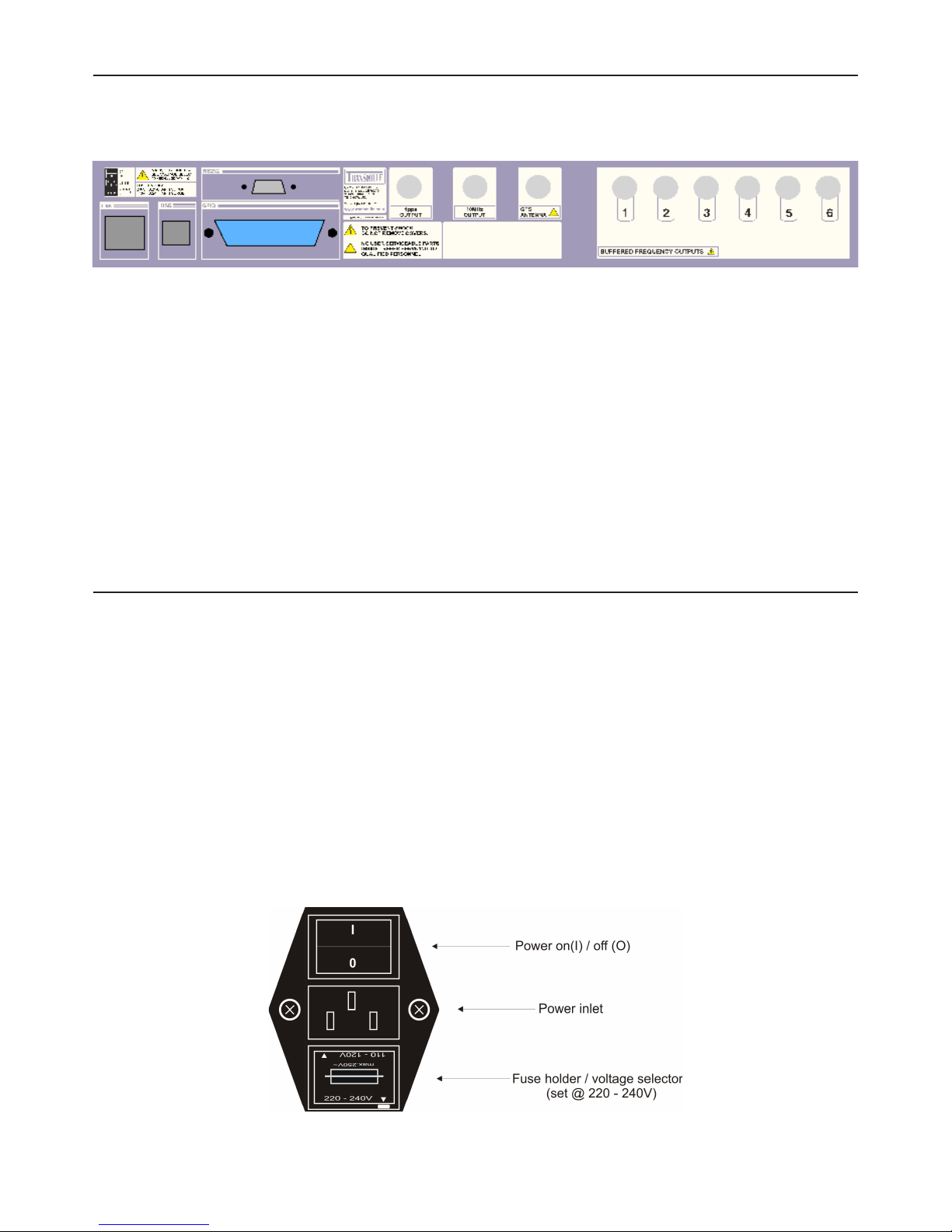
Rear Panel Connecons
Connections are offered on the rear panel of the 8700 as below
On the rear USB, RS232, RJ45 and GPIB connectors can be used for controlling the instrument
remotely. A BNC connector is provided for the GPS antenna input (labelled), 1 PPS output and
dedicated 10 MHz out.
If specified, an option to have 5 additional buffered 10 MHz outputs will be provided each with
independant BNC connectors
Due care should be taken to prevent damage to the internal pins of the BNC connectors by
using only undamaged male BNC cables to connect.
Seng and checking the line voltage
The standard has been designed to work from either 110-120V or 220-240V line supply.
The user should confirm that the correct voltage has been set prior to connecting power to the
instrument. Connecting the instrument to the wrong power supply could cause damage to the
instrument. To change the line voltage, remove the fuse / voltage selector housing from the rear
of the unit, rotate through 180° and replace with he required voltage setting at the bottom of the
housing.
The instrument is set for 110V operation when shipped to the USA, for all other regions the
instrument is shipped set to 230V operation.

Page 9
8700 Operation Manual
Powering up the Instrument
After connecting line power, the instrument can be switched on with the power switch on the
rear of the instrument.
The front panel display will illuminate and the instrument will begin its start up sequence. This
process takes approximately 15 seconds. After powering on, allow the unit to acquire a GPS fix, as
identified on the front panel prior to use.Connecting to a computer
The 8700 is fitted with USB, RS232, GPIB and Ethernet interfaces for connecting to a computer.
For best compatibility with ProCal, Transmille advise that the USB connection is used.
RS232 Interface
Baud Rate 9600
Parity None
Data Bits 8
Stop Bits 1
Cable Type
Male to Female Serial Cable
(9 pin D Type)
Straight through pin
connection (NOT Null Modem)
Software Driver
N/A - If used with Transmille
USB to RS232 adapter FTDI drivers
as provided should be installed
USB Interface
Cable Type
USB ‘A’ Type connector to
USB ‘B’ Connector
Software Driver FTDI USB Driver (supplied)

Page 10
8700 Operation Manual
Ethernet Interface
Configuration
Via optional configuration utility for
computer
Cable Type 100BaseT Ethernet Cable (RJ45)
Software Driver N/A
GPIB Interface
Configuration
Use config menu to set address
Enter new GPIB Address
(Valid range 0-30)
Cable Type GPIB Interface Cable
Software Driver
National Instruments VISA or
equivalent
Page 11
8700 Operation Manual
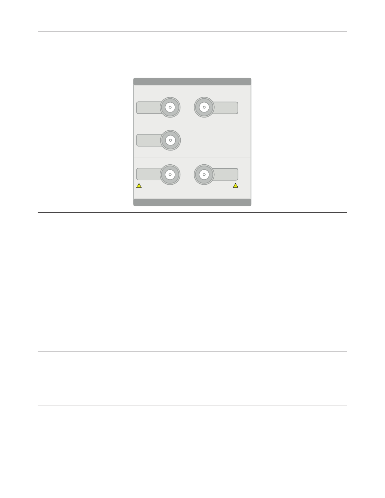
Front Panel Connecons
The 8700 features 5 BNC connectors on the front panel for simple connections to frequency
counters and sources. 3 of the BNC connections are used for SOURCE, 2 of the connectors
are used for MEASURE.
Output Connectors
Output connectors are provided for Low Frequency (up to 10 MHz) outputs A and B, and a
dedicated output for the High Frequency (up to 1.05 GHz) output.
Only the active function will have an output present at the terminal, other terminals are
disconnected while not in use.
Low Frequency output A is used for the primary 10 MHz output, Frequency Divider
(1,2,5 sequence) and Variable level outputs (5V Square and Variable Sine Wave)
Low Frequency output B is only active when in Phase Offset mode.
Input Connectors
Input connectors are provided for both low frequency input (up to 10 MHz) and high
frequency input (up to 1.05 GHz) via two BNC inputs.
Input Characteriscs
The Low Frequency input has an input impedance of 1 MOhm, an input capacitance of
25pF and has a maximum input of 20V
The High Frequency input has an input impedance of 50 Ohms, with a maximum input of 1V
LF SOURCE
A
HF
SOURCE
LF SOURCE
A
HF
MEASURE
LF
MEASURE
1 MOHM / 25pF
MAX. INPUT 20V
50 OHMS
MAX. INPUT 1V
! !
SOURCE TERMINALS
MEASURE TERMINALS
Page 12
8700 Operation Manual
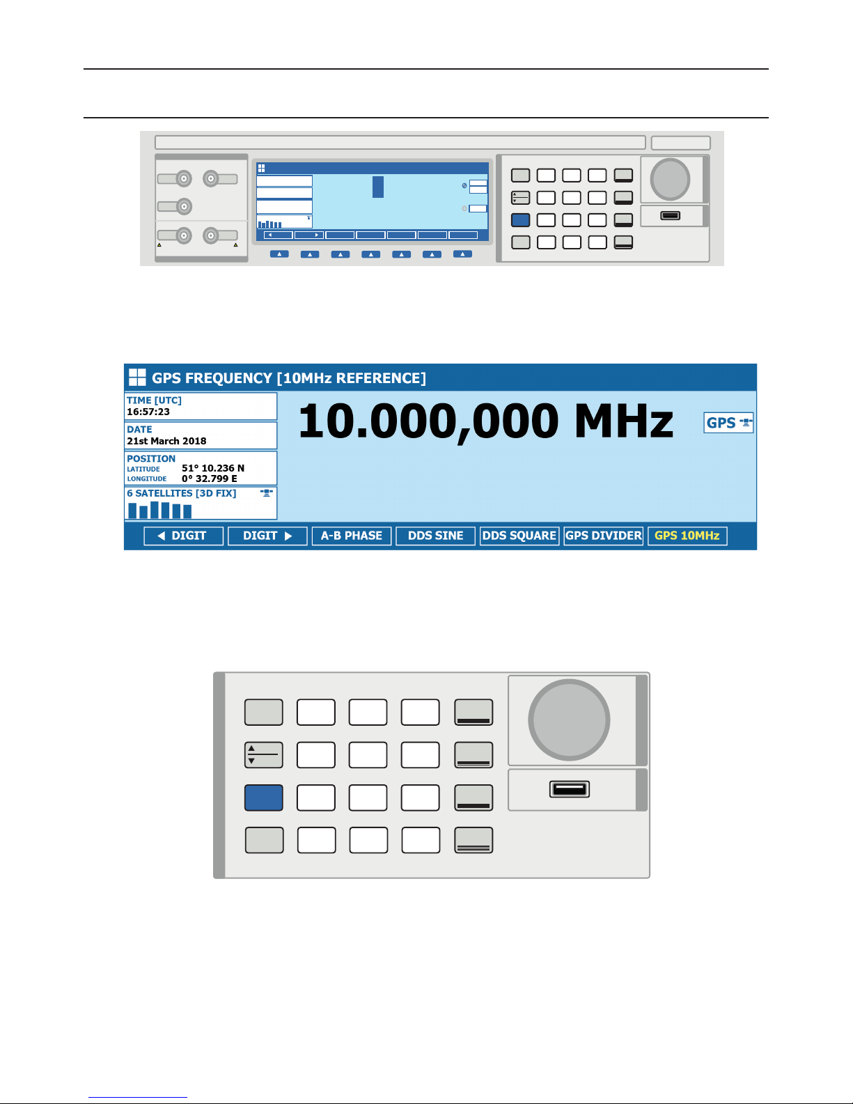
Operaon
Front Panel Controls
For ease of use, the front panel keyboard is separated into two sections.
A dynamic ‘softkey’ section under the display for function related modes of operation.
A function control section to access major function selection and value entry, including
a digital control for easy increment / decrement of values.
LOG 123
LOW FREQUENCY SOURCE [DDS SINE WAVE]
INT
DIGIT DIGITA -B PHASE DDS SINE DDS SQUARE GPS DIVIDERG PS 10MHz
Impedance @ 50 Ohms = 0.50V
010.000 kHz
1.00V
RMS
OUTPUT
TIME [UTC]
16:57:23
DATE
21st March 2018
POSITION
51° 10.236 N
0° 32.799 E
LATITUDE
LONGITUDE
6 SATELLITES [3D FIX]
MENU
FREQ.
ENTER
SHIFT
LEVEL
7
4
1
•
8
5
2
0
7
4
1
1
LF
SOURCE
HF
SOURCE
LF
MEASURE
HF
MEASURE
DIGITAL CONTROL
DATA PORT
kHzM Hz
GHz
EXP
BACKSPACE
SELF TEST
RESET
INFO
8700 SOURCE / MEASURE GPS FREQUENCY STANDARD
FUNCTION CONTROL
LF SOURCE
A
HF
SOURCE
LF SOURCE
A
HF
MEASURE
LF
MEASURE
1 MOHM / 25pF
MAX. INPUT 20V
50 OHMS
MAX. INPUT 1V
! !
SOURCE TERMINALS
MEASURE TERMINALS
MENU
FREQ.
ENTER
SHIFT
LEVEL
7
4
1
•
8
5
2
0
7
4
1
1
LF
SOURCE
HF
SOURCE
LF
MEASURE
HF
MEASURE
DIGITAL CONTROL
DATA PORT
kHzM Hz
GHz
EXP
BACKSPACE
SELF TEST
RESET
INFO
FUNCTION CONTROL
Page 13
8700 Operation Manual
LOG 123
LOW FREQUENCY SOURCE [DDS SQUARE WAVE]
INT
DIGIT DIGITA -B PHASE DDS SINE DDS SQUARE GPS DIVIDERG PS 10MHz
5V pk-pk @ 1 MOhm
010.000 kHz
TIME [UTC]
16:57:23
DATE
21st March 2018
POSITION
51° 10.236 N
0° 32.799 E
LATITUDE
LONGITUDE
6 SATELLITES [3D FIX]
AWAITING
GPS SIGNAL
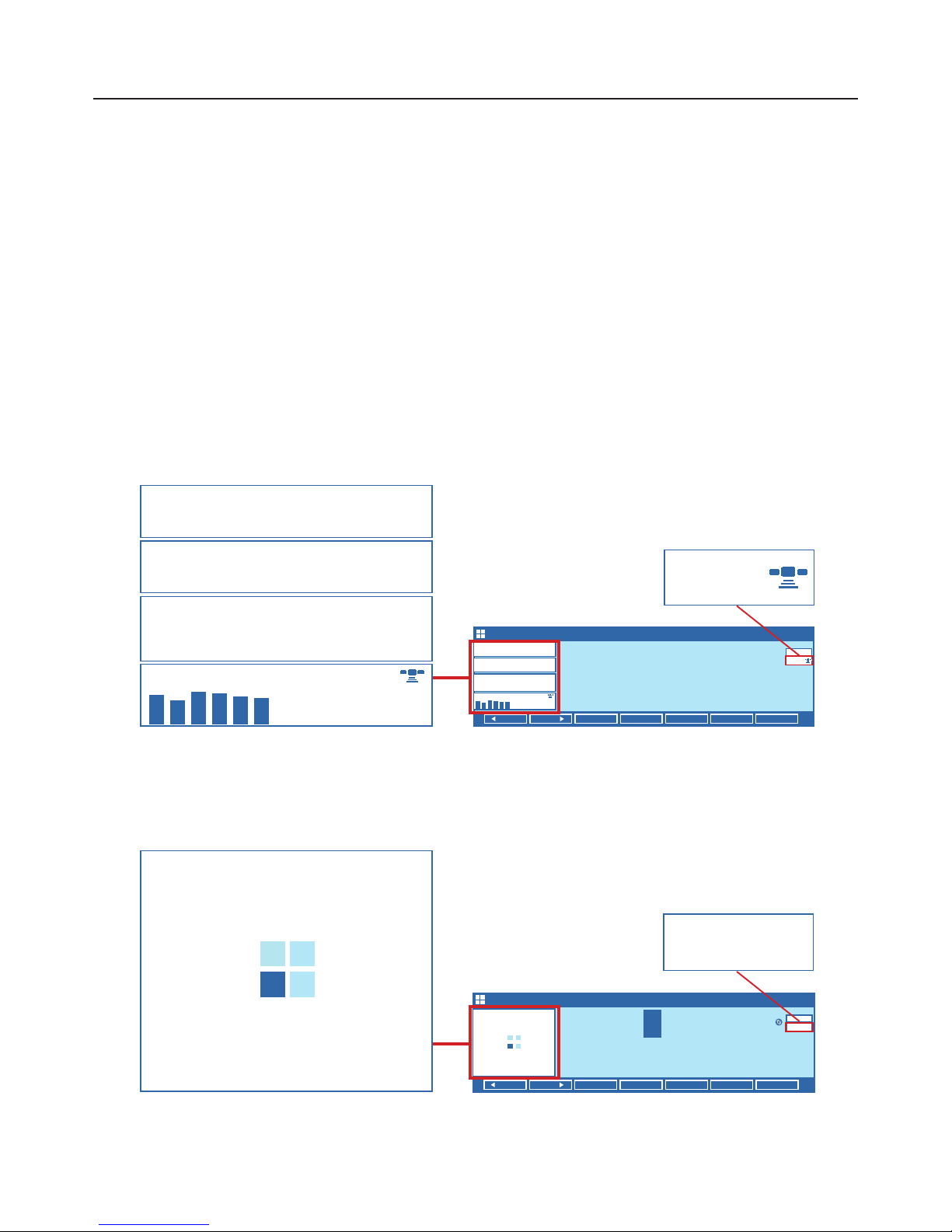
GPS Status Display
The main display of the 8700 is a full colour 7.2” LCD. This screen displays GPS signal data
and either the current SOURCE or the MEASURE information depending upon the mode.
At the left hand side of the screen detailed GPS data is displayed if a signal fix has been
successfully acheived. If GPS signal fix has not yet been acheived this section will display an
‘Awaiting GPS Signal’ indicator. GPS signal fix may take up to 20 minutes after installation,
however should not appear during normal use.
If a GPS signal fix has been acheived the 10 MHz reference is disciplined to the GPS system
GPS signal fix achieved
GPS indicator denotes GPS DERIVED 10MHz reference in use
No GPS Fix
INT indicator denotes INTERNAL 10MHz reference in use
LOG 123
GPS FREQUENCY [10MHz REFERENCE]
TIME [UTC]
16:57:23
DATE
21st March 2018
POSITION
51° 10.236 N
0° 32.799 E
LATITUDE
LONGITUDE
6 SATELLITES [3D FIX]
GPS
10.000,000 MHz
DIGIT
DIGITA -B PHASE DDS SINE DDS SQUARE GPS DIVIDER GPS 10MHz
TIME [UTC]
16:57:23
DATE
21st March 2018
POSITION
51° 10.236 N
0° 32.799 E
LATITUDE
LONGITUDE
6 SATELLITES [3D FIX]
AWAITING
GPS SIGNAL
GPS
INT
Page 14
8700 Operation Manual
Source Funcons
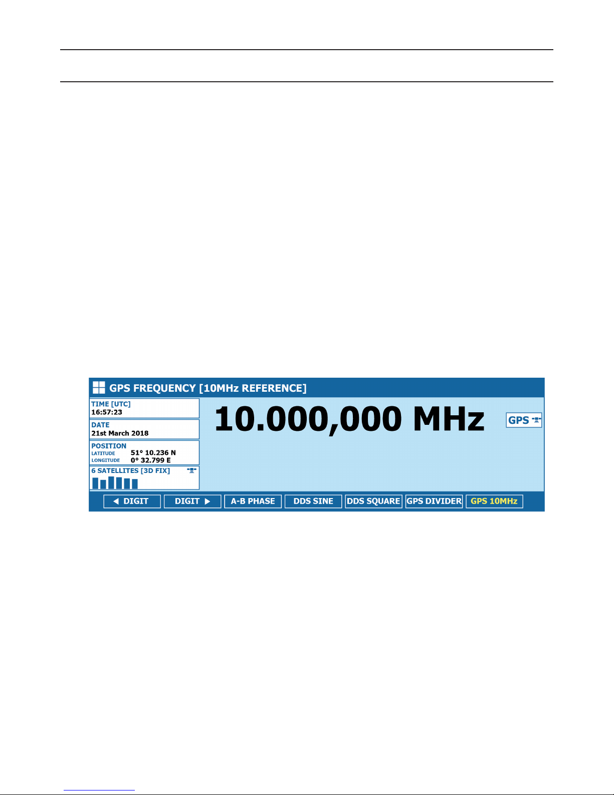
GPS FREQUENCY [10MHz REFERENCE]
The default start up state for the 8700 is for the 10 MHz reference frequency signal
This can also be selected using the GPS 10MHz softkey when in LF SOURCE mode.
The function display in the title bar of the display will indicate
GPS FREQUENCY [10MHz Reference]
This output is disciplined to GPS and requires no calibration to maintain specifications
as long as a GPS lock is achieved.
In this mode the Main Display will indicate 10 MHz, followed by either INT or GPS.
A display of GPS indicates that the unit is currently disciplined to GPS, a display of INT means
that a fix has not been achieved and the 8700 is using the internal 10MHz reference.
The output for this function appears at the LF Source A Terminal
Page 15
8700 Operation Manual
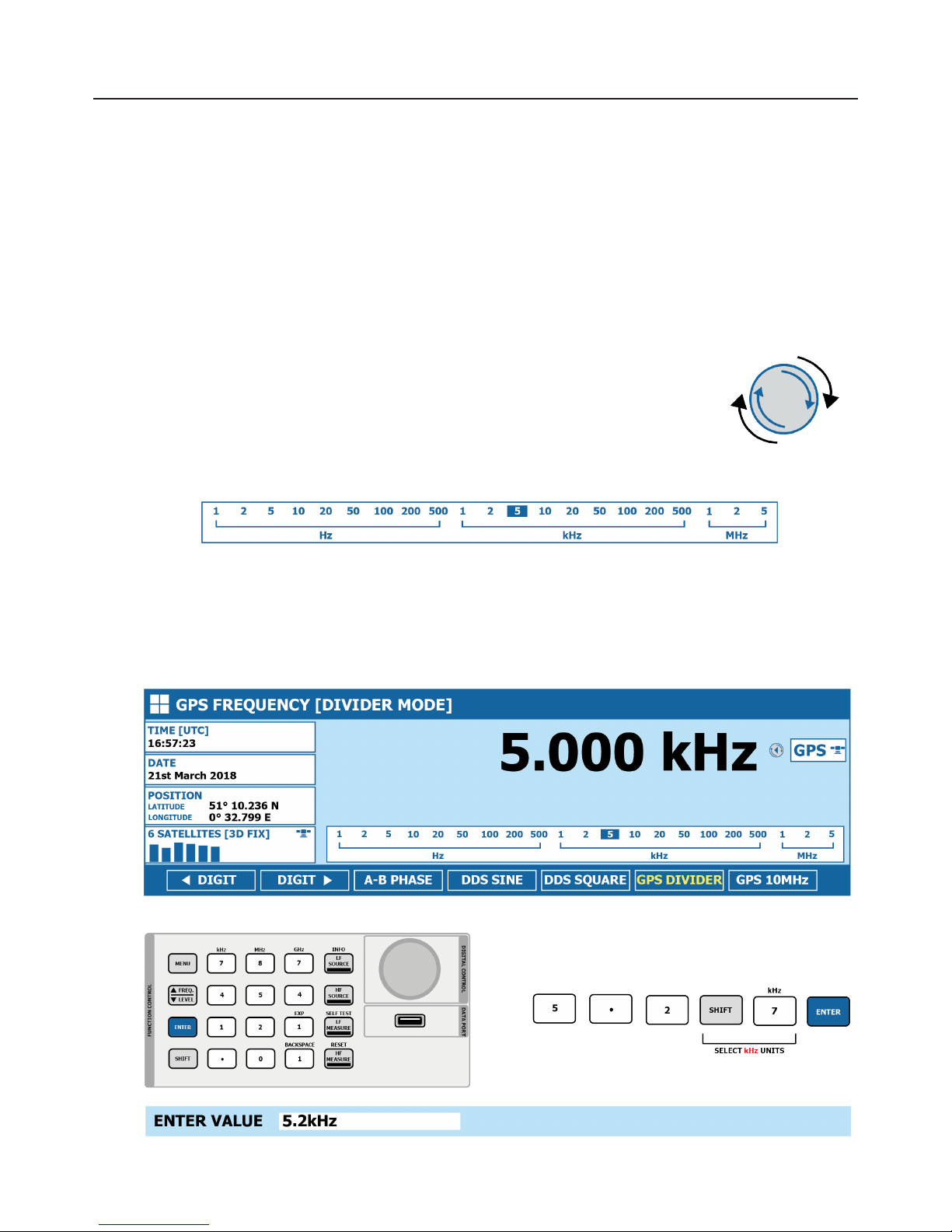
GPS FREQUENCY [DIVIDER MODE]
Pressing the GPS DIVIDER softkey when the unit is in LF SOURCE mode will set the 8700 to
GPS FREQUENCY [DIVIDER MODE]. In this mode the output frequency can be varied in steps
of 1, 2, 5 from 1 Hz to 5 MHz.
In this mode the Main Display will indicate 10 MHz, followed by either INT or GPS.
A display of GPS indicates that the unit is currently disciplined to GPS, a display of INT means
that a fix has not been achieved and the 8700 is using the internal 10MHz reference.
The output is varied using the digital control, rotating clockwise to INCREASE
the frequency, and anti-clockwise to DECREASE the frequency.
A convenient selection display panel shows the currently selected frequency
from the values available in this mode.
Direct digit entry is also possible using the numerical section of the keyboard, followed by
pressing the ENTER key. Entries which are not valid will select the next available frequency
(i.e. an entry of 300 Hz will select the 500 Hz output.
The output for this function appears at the LF Source A Terminal
 Loading...