

Transmille 8100 Series Operation Manual

www. transmille.com

8100 Operation Manual - V1.0.1
www.transmille.com
Version 1.0.1 - 18th June 2018
Page 1

8100 Operation Manual - V1.0.1
Warranty
Transmille guarantees this product to be free from defects in material and workmanship under
normal user for a period of one (1) year from the date of shipment. This warranty does NOT cover any
required re-calibration/adjustment or standard maintenance actions. This warranty extends only to the
original end purchaser and does not apply to fuses, batteries, external cables or to the product if it has
been modified, misused, altered or has been subjected to mishandling or misuse.
Transmille’s obligation to warranty is limited to repair or replace the product after return to
an authorized Transmille service centre within the warranty period and is subject to Transmille’s
investigation determining that the fault is not caused by misuse, alteration or through mishandling.
If failure occurs, send the product via pre-paid freight, to the service centre as informed by
Transmille with a description of the fault only after receiving confirmation from Transmille. At
Transmille’s option, either repairs will be performed or a replacement unit of similar condition and
age will be provided.
Transmille will return the product to the end customer or local distributor via pre-paid freight
(with exception of any customs clearance fees).
Transmille accept no responsibility for damage during return shipping for warranty service.
Page 2
www.transmille.com

8100 Operation Manual - V1.0.1
Introduction .......................................................................8
Key Features ......................................................................................8
Available Accessories .........................................................................8
Basic Operation .................................................................9
Front Panel .........................................................................................9
Input Terminals ...................................................................................9
Display ...............................................................................................10
Measurement Display ...........................................................11
Status Indication ...................................................................11
Display Elements ..................................................................11
Soft Key Text ........................................................................12
Range / Function Indicator ....................................................12
Configuration Information ......................................................12
On Screen Keyboard ............................................................13
Keyboard ............................................................................................13
Major Function Keys ...........................................................................13
Menu / Parameter Keys ......................................................................14
Null .......................................................................................14
Digits ....................................................................................14
Filter .....................................................................................15
Trig .......................................................................................15
Input .....................................................................................15
Shift ......................................................................................15
Config ...................................................................................16
Menu ....................................................................................16
Exit .......................................................................................16
Enter ....................................................................................16
Soft Keys ............................................................................................16
Numeric Keyboard ..............................................................................17
Digital Control .....................................................................................17
USB Device Port .................................................................................18
Electrometer Terminals (8104 Only) ....................................................18
Rear Panel .........................................................................................19
Power Inlet, Fuses & Voltage Selector ..................................19
LAN Interface........................................................................19
USB Interface .......................................................................19
RS232 Interface ....................................................................19
GPIB Interface ......................................................................20
Serial Number .......................................................................20
Rear Panel Inputs (8104 only)...............................................20
Current Fuses .......................................................................20
Power On Defaults ..............................................................................20
Contents
Menus .................................................................................21
Main Menu .........................................................................................21
CALIBRATION .....................................................................21
COUPLING ...........................................................................21
DEFAULTS ...........................................................................21
DISPLAY ELEMENT CONFIGURATION ................................21
ERROR LOG ........................................................................21
www.transmille.com
Page 3

8100 Operation Manual - V1.0.1
FILTER .................................................................................21
FREQUENCY GATE .............................................................22
FUNCTION ...........................................................................22
GUARD ................................................................................22
HELP ....................................................................................22
INPUT...................................................................................22
INSTRUMENT INFORMATION ..............................................22
INTERNAL TEMPERATURE .................................................22
LIMITS ..................................................................................23
MATHS .................................................................................23
OHMS COMPENSATION ......................................................23
OHMS TEST CURRENT .......................................................23
PRESET ...............................................................................23
RATIO CONFIGURATION .....................................................24
RESET .................................................................................24
RESOLUTION ......................................................................24
SELF TEST...........................................................................24
SHUNT CONFIGURATION....................................................24
SPECIFICATION CONFIGURATION .....................................24
TEMPERATURE UNITS ........................................................24
TRIGGER MODE ..................................................................24
UNCERTAINTY CONFIGURATION .......................................25
Configuration Menu.............................................................................25
DATE & TIME .......................................................................25
FIRMWARE UPDATE [VIA USB DEVICE PORT] ..................25
REGIONAL SETTINGS .........................................................26
REMOTE INTERFACE SETTINGS ........................................27
SCREEN SAVER TIMEOUT ..................................................27
SOUND ................................................................................27
SYSTEM PASSWORD ..........................................................27
Calibration Menu.................................................................................27
CALIBRATION MODE ..........................................................27
BACKUP CALIBRATION FACTORS ......................................28
RESTORE CALIBRATION FACTORS ...................................28
Display Element Configuration Menu ..................................................29
Performing Measurements ................................................30
General Guidelines .............................................................................30
Measurement Considerations..............................................................30
DC Voltage .........................................................................................32
Selecting A Range ................................................................32
Measurement Resolution ......................................................32
Configuring Sample Rate ......................................................33
Performing A Null .................................................................33
Example Connection .............................................................35
AC Voltage .........................................................................................37
Selecting A Range ................................................................37
Measurement Resolution ......................................................37
Configuring Sample Rate ......................................................38
Selecting Frequency Gate .....................................................38
Configuring AC / DC Coupling ...............................................40
Example Connection .............................................................41
Page 4
www.transmille.com

8100 Operation Manual - V1.0.1
DC Current .........................................................................................43
Selecting A Range ................................................................43
Measurement Resolution ......................................................44
Configuring Sample Rate ......................................................44
Performing A Null .................................................................45
Example Connection .............................................................46
DC Current - Electrometer Input (8104 Only) ......................................48
Selecting A Range ................................................................49
Measurement Resolution ......................................................49
Configuring Sample Rate ......................................................49
Performing A Null .................................................................50
Example Connection .............................................................51
AC Current .........................................................................................53
Selecting A Range ................................................................53
Measurement Resolution ......................................................53
Configuring Sample Rate ......................................................54
Configuring AC / DC Coupling ...............................................55
Selecting Frequency Gate .....................................................56
Example Connection .............................................................57
Resistance - 2 Wire ............................................................................59
Selecting A Range ................................................................59
Measurement Resolution ......................................................60
Configuring Sample Rate ......................................................60
Configuring Measurement Current ........................................61
Performing A Null .................................................................61
Example Connection .............................................................63
Resistance - 4 Wire ............................................................................65
Selecting A Range ................................................................65
Measurement Resolution ......................................................66
Configuring Sample Rate ......................................................66
Configuring Measurement Current ........................................67
Configuring Ohms Compensation ..........................................68
Performing A Null .................................................................69
Example Connection .............................................................71
High Value Resistance (8104 Only) .....................................................73
Configuring Measurement Voltage ........................................74
Selecting A Range ................................................................74
Measurement Resolution ......................................................74
Configuring Sample Rate ......................................................75
Performing A Null .................................................................75
Example Connection .............................................................77
Temperature Measurement - PRT / RTD (8104 Only) ..........................78
Configuring a Probe ..............................................................79
Configure Probe Information .................................................79
Configure Probe Wiring Scheme ...........................................81
Configure Probe Terminals ....................................................81
Configure Probe Linearisation ...............................................82
Saving Probe Configuration ..................................................83
Selecting a Probe .................................................................84
Measurement Resolution ......................................................84
Configuring Sample Rate ......................................................85
www.transmille.com
Page 5

8100 Operation Manual - V1.0.1
Configuring Temperature Units ..............................................86
Configuring Ohms Compensation ..........................................87
Performing A Null .................................................................88
Example Connection (2 Wire PRT / RTD) ..............................88
Example Connection (3 Wire PRT / RTD) ..............................88
Example Connection (4 Wire PRT / RTD) ..............................89
Temperature Measurement - Thermocouple (8104 Only) .....................90
Selecting Thermocouple Type ...............................................90
Configuring Cold Junction Compensation (CJC) ....................91
Measurement Resolution ......................................................92
Configuring Sample Rate ......................................................93
Example Connection (TCLEAD) ............................................93
Example Connection (Direct Connection) ..............................94
Ratio Measurements (8104 Only) ......................................95
Configuring Ratio Measurements ........................................................95
Available Ratio Modes ........................................................................96
Performing a Ratio Measurement ........................................................96
Ratio To Value ....................................................................................97
Shunt Current Measurement (8104 Only) ..........................97
Shunt Configuration ............................................................................97
Selecting and using a Shunt ...............................................................99
Example Connection ...........................................................................100
Maths Operations ...............................................................101
Arithmetic Functions ...........................................................................101
Multiply by m ........................................................................101
Divide by d............................................................................102
Subtract n .............................................................................102
Sequential Arithmetic ............................................................102
Averaging Functions ...........................................................................102
Rolling Average ....................................................................102
Block Average .......................................................................102
Remote Operation ..............................................................104
Native Commands ..............................................................................104
Command Structure ..............................................................104
Command Response Codes .................................................104
Setting Ranges/Functions .....................................................105
AC Voltage ...........................................................................105
DC Voltage ...........................................................................105
AC Current ...........................................................................105
DC Current ...........................................................................105
4 Wire Resistance - Low Current .........................................105
4 Wire Resistance ...............................................................105
2 Wire Resistance - Low Current .........................................105
2 Wire Resistance ...............................................................106
Thermocouple (8104 Only)....................................................106
PRT (ITS-90 Linearisation) (8104 Only) ................................106
PRT (IEC751 Linearisation) (8104 Only) ...............................106
Electrometer Output Voltage (8104 Only) ..............................106
Measurement Parameters .....................................................107
Obtaining Readings ..............................................................107
Setting Resolution ................................................................107
Page 6
www.transmille.com

8100 Operation Manual - V1.0.1
Setting Filter .........................................................................107
System Functions .................................................................107
Enable / Disable Backlight ....................................................107
Reset to Startup Parameters .................................................108
Query Instrument ID .............................................................108
Query Instrument Internal Temperature .................................108
Perform backup of Calibration Factors ..................................108
Calibration & Verification ..................................................109
Introduction .........................................................................................109
Calibration Instructions .......................................................................109
Important Notes ..................................................................................109
www.transmille.com
Page 7

8100 Operation Manual - V1.0.1
Introduction
The 8100 Series Digital Multimeter is a high performance instrument capable of reading a
wide range of input signals. Available as two models, accuracies of up to 4ppm, are available while
maintaining an easy to use interface that is familiar to users of similar equipment.
Key Features
• AC/DC Volts to 1025V
• AC/DC Current to 30 Amps
• Dedicated Low Current inputs for high sensitivity measurements (8104 Only)
• 2 and 4 Wire Resistance with selectable current
• High Resistance Measurement to 1 TOhm (8104 Only)
• Frequency Measurement
• Thermocouple Measurement with Automatic Cold Junction (8104 Only / Requires
TCLEAD)
• PRT Measurement with conversion to ITC-90 and IEC751 (8104 Only)
• Electronically switchable Front and Rear Terminals (8104 Only)
• Multi Interface (RS232, USB, GPIB/IEEE 488, Ethernet
The 8100 Series has a full range of complimentary accessories to assist with getting the best out
of the Instrument. Accessories include:
• A Soft Carry Case for hand carried transit (8100-SCASE)
• A Hard Transit case, laser cut with storage areas for leads and accessories for shipping
via courier (8100-TCASE)
• A comprehensive lead set that includes leads and accessories for making high
performance measurements (8100-LEAD)
• Options for Rack Mount configuration (RACKTRAY and 8100-RACKCASE)
• Automated Cold Junction Measurement lead (TCLEAD)
Available Accessories
Page 8
www.transmille.com

The 8100 Front Panel has been designed to be easy to operate with inputs located on the Left
hand side and clearly labelled keys.
8100 Operation Manual - V1.0.1
Basic Operation
Front Panel
Input Terminals
Warning
To avoid electrical shock, injury of death, never touch any lead connected (or terminal) of the
multimeter unless certain that no dangerous voltages are present.
The 8100 Series Multimeter’s offer Front and Rear (8104 Only) Terminals. The default set of
terminals on start up is always the Front Panel Terminals. When front panel input is selected the active
set of terminals are indicated with a green LED Indicator next to the terminals.
Take care to avoid overloading the inputs. Each input has the maximum input labelled next to
the input, with more information available in the extended specifications.
The Front and Rear Inputs of the 8104 can be selected using the INPUT menu or over the
remote interface. When the 8104 is using REAR panel inputs the indicator in the top right of the
www.transmille.com
Page 9
screen will display ‘REAR’
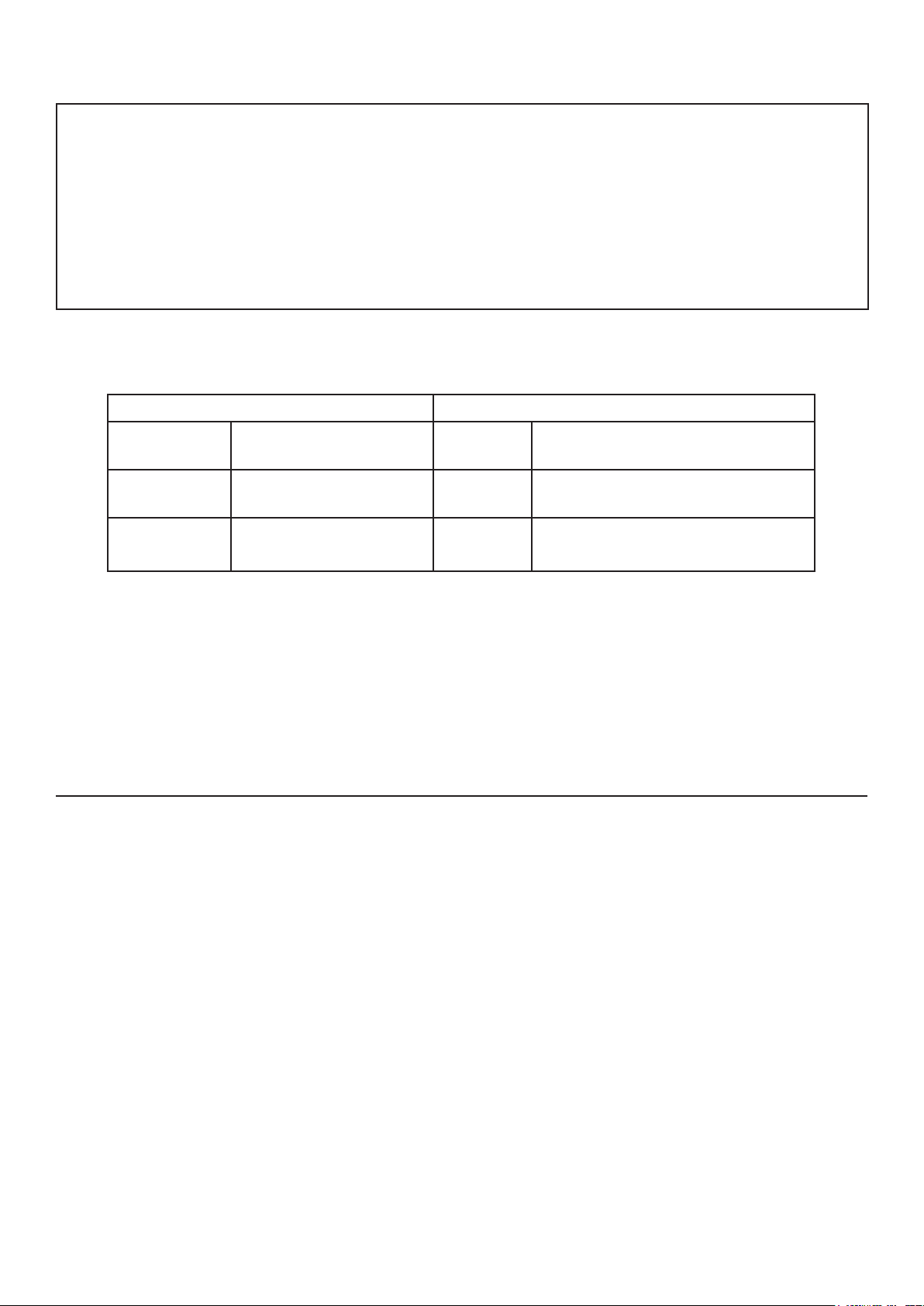
The function of each terminals is indicated as in the table below
Sense Ω Current Ω
V+
V-
Voltage High
Ohms High (2 Wire)
Voltage Common
Ohms Common (2 Wire)
Guard I+
8100 Operation Manual - V1.0.1
Front and Rear Input Terminals
I+
I-
Current High (Up to 1A)
Ohms High (4 Wire)
Low Current (Below 1A) Common
Ohms Common (4 Wire)
High Current High (Above 1A)
(Front Only)
4mm Terminals are provided on the front panel terminals for connection via both standard 4mm
plugs as well as spade and bare wire connections.
On the 8104 rear panel connections are provided in the form of 4mm sockets.
The 8100 features a large full colour screen that displays measurements and menu screens.
The 8100 Screen is segmented into 5 main sections during use :
1. Measurement Display
2. Status Indication
3.
4. Soft Key Text
5. Range / Function Indication
Display
Page 10
www.transmille.com

8100 Operation Manual - V1.0.1
6.
Note : To ensure long life of the screen it is normal behaviour for the screen to go into
screen saver and dim the backlight after a user configurable length of time
Measurement Display
The measurement display shows the last sample obtained by the multimeter, or when in maths
or ratio functions the result of the user configured parameters.
In AC Modes the frequency will be displayed below the Main Measurement, where as in DC
modes the DC indicator will be displayed
On the right hand side of the Measurement Display the current Filter speed, the Resolution and
the sample indicator (SMPL) are displayed
The SMPL indicator will flash to indicate that a new sample has been obtained, and for longer
sample times will provide a countdown to the next sample.
Status Indication
If MATHS functions such as Multiply have been enabled below the Status indicator text
indicating the currently active maths function
Display Elements
The 8100 Series allows up to 4 user selectable ‘Display Elements’ to be visible on screen at
any one time. The display elements can provide the user with additional insights to their measurement
such as the Specification of the multimeter, the Uncertainty of the Measurement, Standard Deviation
www.transmille.com
Page 11
8100 Operation Manual - V1.0.1
and more.
Information on configuring the active Display Elements can be found on Page 21
Soft Key Text
The Soft Key Text depicts the function that the corresponding physical soft key (described on
Page 16) will perform. This text will vary depending upon the current range and function as well as
the menu that is currently active
Range / Function Indicator
The Range / Function indicator appears in the top left corner of the screen. This indicates
RESISTANCE
Conguration Information
Information regarding the current configuration of the multimeter such as the Input Terminals
(8104), whether or not a Null is presently applied and the if the multimeter is in Manual or Auto
Range state is displayed at the top of the measurement screen.
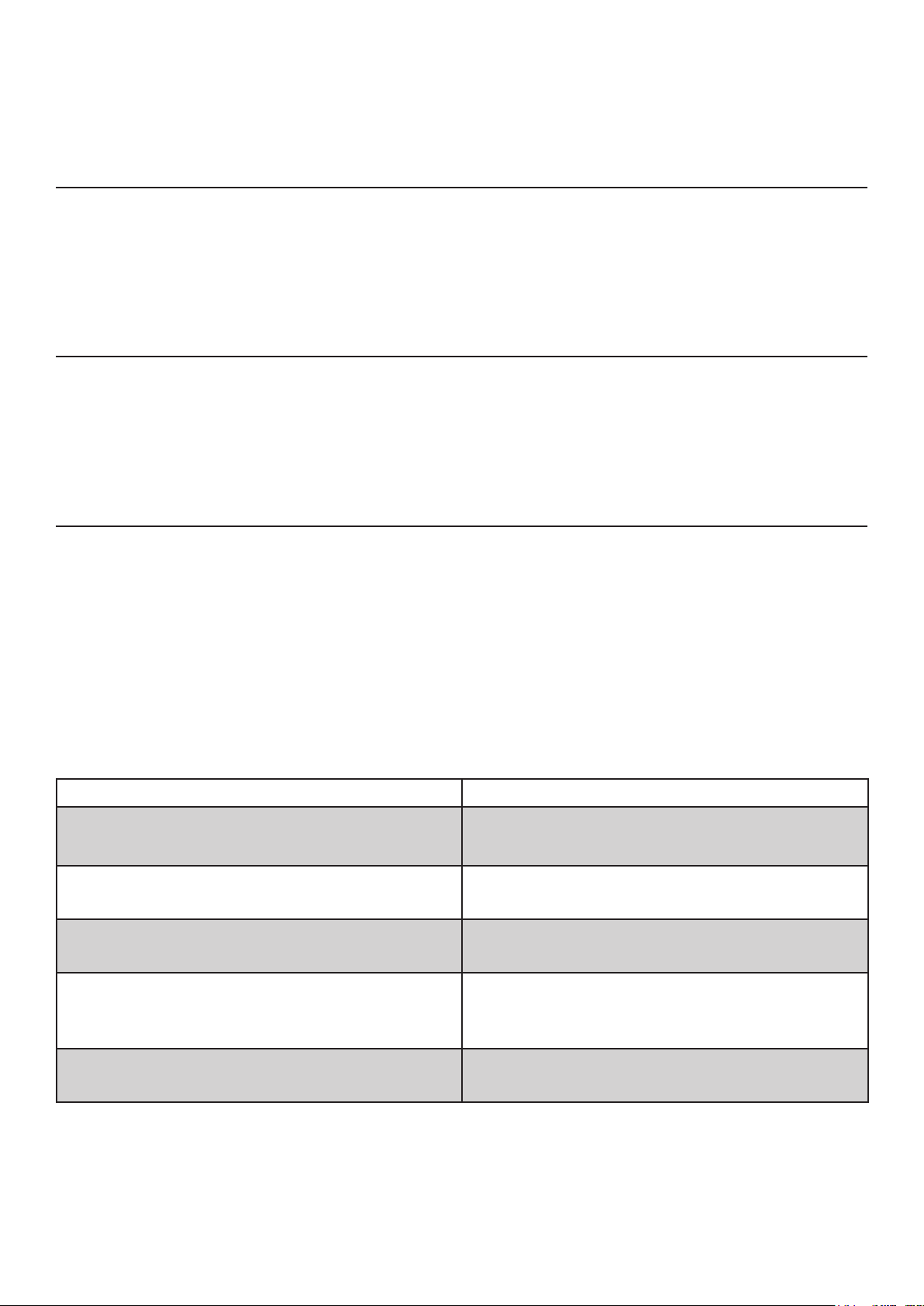
Further information regarding icons that appear in the Configuration Information portion of the
screen can be found through this manual, however a summary of icons and their description can be
found below
Icon Text
FRONT or REAR Indicates the currently active set of Terminals
NULL Indicates that a Null is presently active for the se-
lected Range and Input Terminal
COMP Indicates that Ohms Compensation is presently
Description
active
Page 12
REMOTE Indicates that the multimeter is currently under Re-
mote Operation. Input via the keyboard is disabled
with exception of the LOCAL so key
GPIB xx Indicates that instruments GPIB address when in
Remote Mode
www.transmille.com

8100 Operation Manual - V1.0.1
On Screen Keyboard
When Text entry is required (Such as entering the system password) an on screen keyboard is
displayed on the screen.
Navigation is performed by using the DIGITAL CONTROL to highlight the desired key and
then pressing the DIGITAL CONTROL or the ENTER key. When text entry is complete, the soft key
labelled ENTER
The 8100 Series features 3 types of keys, separated into two main areas :
1. Major Function Keys
2. Menu / Parameter Keys
3. Soft Keys - These keys are context sensitive and the function changes depending upon the menu
or function selected.
Keyboard
There are 8 Function Keys, which are white in colour. These keys provide direct access to
functions and ranges, such as DC Voltage or DC Current.
www.transmille.com
Major Function Keys
Page 13

8100 Operation Manual - V1.0.1
Menu / Parameter Keys
There are 8 Menu / Parameter keys, which are grey in colour. These keys provide fast access to
menus or measurement functions such as NULL, INPUT and DIGITS
In the Menu / Parameter keys section of the keyboard there are two special function keys,
MENU and SHIFT. The MENU key is highlighted BLUE and the SHIFT key is clear, yet illuminates
BLUE when selected.
Null
Pressing the NULL key will trigger a maths null function, in which the currently displayed
measurement will be subtracted from subsequent measurements. A Message will appear indicating the
value that has just been stored as the NULL value and the NULL indicator will appear at the top of the
screen.
Pressing the NULL key a second time will disable the NULL on the present range. A message
will be displayed to indicate that the null has been cleared.
The DIGITS key displays the resolution menu, allowing the user to select the resolution of the
measurement. The resolution is selectable using the soft keys below the desired resolution.
Depending upon the function and filter speed the resolution options will vary. The maximum
resolution is 8 digits for the 8104 and 7 digits for the 8109.
Digits
Page 14
www.transmille.com

8100 Operation Manual - V1.0.1
The FILTER key displays the filter menu, allowing the user to select the filter / measurement /
sample rate. The filter is selectable using the soft keys below the desired filter speed.
The range of filters / sample rate available will vary depending upon the resolution selected.
Lower resolutions offer faster sample rates.
The FILTER menu is separated into two menus, the first listing filter speeds from 125ms to 2s,
the second listing speeds 4s through 32s.
To switch between the two screens press the >> or << keys when displayed
Filter
Trig
The TRIG key displays the trigger menu, allowing the user to select the triggering method from
the front panel. The trigger method is selectable using the soft keys below the desired trigger method.
When the trigger menu is displayed the user can perform a manual trigger event by pressing the
MANUAL soft key
Input
The INPUT key displays the input menu, allowing the user to select the desired input terminals.
The INPUT key also allows access to RATIO functions.
The desired input mode is selected using the soft keys to select the input mode.
On 8109 units this button will not display a menu as only front panel inputs are available.
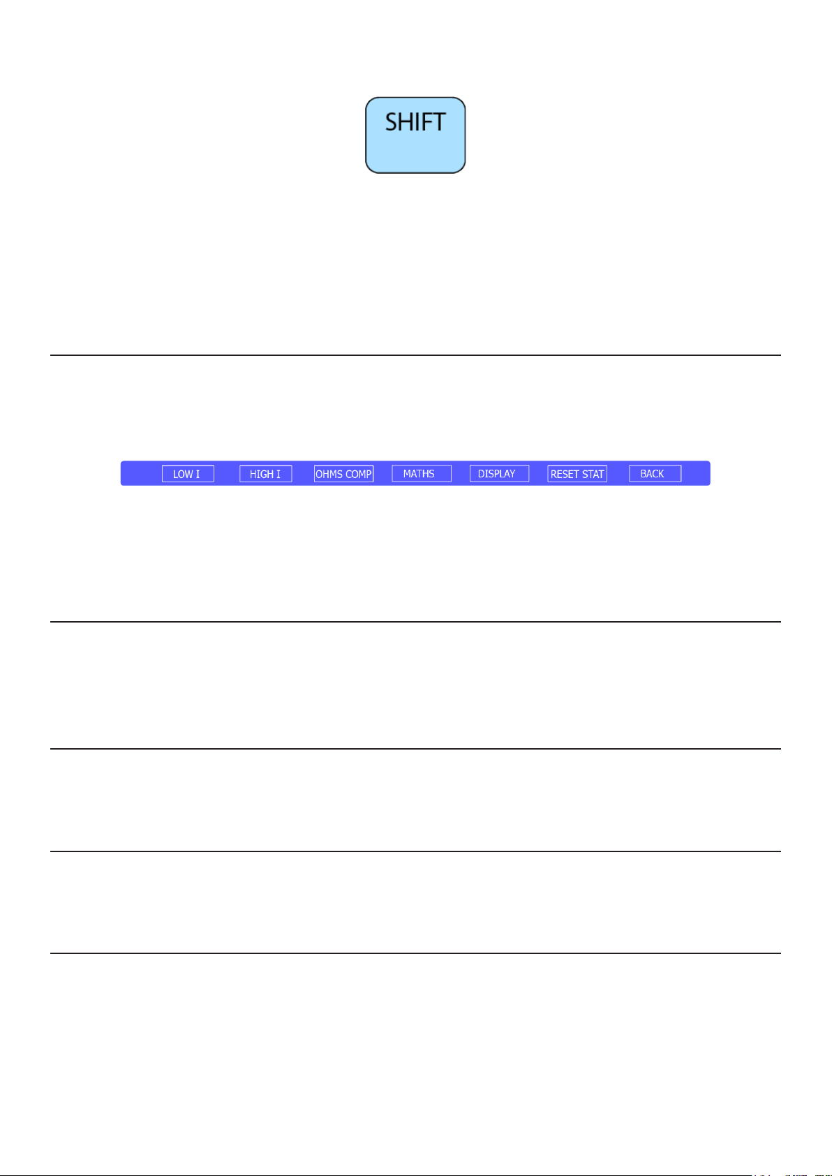
Shift
The SHIFT key is a special function key that allows sub functions to be accessed. When the
shift key has been pressed it will illuminate BLUE. The secondary text on the label then becomes
www.transmille.com
Page 15
8100 Operation Manual - V1.0.1
active instead of the printed text.
Examples of SHIFT key functions are SHIFT key followed by ENTER which triggers a reset to
default start up conditions.
SHIFT key functionality is disabled after a key is pressed or by pressing the SHIFT key again
The CONFIG key displays the configuration menu, this enables the user to configure function
options, maths functions, display parameters or to reset measurement statistics.
Cong
The CONFIG menu is range and function sensitive, so the display will be different depending
upon the range or function that is currently set.
The menu key displays the full screen menu allowing access to additional functionality and
settings. The Main Menu is described in detail starting from Page 21
The exit key exists any full screen menu and returns to the main measurement screen
The enter key completes digit entry or selects the currently highlighted option in on screen
menus
Menu
Exit
Enter
Soft Keys
There are 7 Soft Keys which are Blue in Colour. The function of these keys is function / menu
sensitive. For example, when in DC Voltage the soft keys provide direct selection of ranges. When in
the Input menu the keys offer selection of the currently active input.
The number of selectable keys will vary depending upon the function.
Page 16
www.transmille.com

8100 Operation Manual - V1.0.1
Numeric Keyboard
When number entry is required the keyboard will automatically enter numerical entry mode.
The numerical indicator at the bottom left hand side of keys will become active and when pressed will
enter digits instead of the function / menu printed on the key.
Digital Control
The digital control provides a method of navigating through menus, selecting items as well as
interacting with the on screen keyboard.
The Digital Control provides both Clockwise and Anti-Clockwise control as well as push to
click functionality. The Digital Control offers a tactile feel to indicate that the position has been
rotated by an increment
To navigate through a menu, a rotation in the clockwise direction results in the menu selection
moving down one position, an anti-clockwise rotation results in moving up one position.
Pushing the Digital Control duplicates behaviour of the physical ENTER key or the SELECT
key when in menus to speed up navigating through menus or data entry
Note - Care should be taken to not PULL on the Digital Control to avoid damage
www.transmille.com
Page 17

8100 Operation Manual - V1.0.1
USB Device Port
The USB Device Port enables the 8100 to Read and Write to USB Memory Sticks for
application of firmware updates or offload of data (such as calibration backup files)
Note - This interface is not used for remote control of the 8100. Connection to a
COMPUTER or CONTROL DEVICE through the use of adapters may cause damage to the USB
port
Electrometer Terminals (8104 Only)
The 8104 Multimeter comes standard with Electrometer functionality, adding low current
(10nA to 10uA Ranges) and High Resistance (up to 1TOhm / 300V) features.
To enable these extended ranges shielded connectors are required to minimise noise due to
unscreened connections. The Electrometer function input is proved through two female BNC inputs on
the right hand side of the Front Panel
Page 18
No rear terminal functionality is available for the Electrometer Functionality
Warning - The Electrometer terminal marked Vout is capable of SOURCING 300V
www.transmille.com

The power inlet of the 8100 is on the left hand side of the rear of the unit. The power inlet
accepts a 3 pin C13 cable.
Below the power inlet is a fuse holder that holds the mains fuses for the unit and also provides
voltage selection.
8100 Operation Manual - V1.0.1
Rear Panel
Power Inlet, Fuses & Voltage Selector
The units ON/OFF switch is contained within the integrated power inlet.
Warning : When replacing the fuse holder ensure that the orientation is for the
appropriate mains input voltage. Failure to do so could result in damage to the instrument
Note : Any mains cable connected to the 8100 should have its earth pins connected to
ground. Failure to do so could result in damage to the instrument
LAN Interface
The instruments LAN interface for remote control over Ethernet.
USB Interface
The instruments USB interface for remote control over USB. The 8100 will appear to the
computer as a RS232 port for easy use in software, and is automatically detected by ProCal.
The Instruments RS232 interface for remote control over RS232 / Serial.
Note : The Instrument uses a straight through RS232 connection. The instrument will not
communicate if a Null Modem cable is used
www.transmille.com
RS232 Interface
Page 19

The Instruments GPIB interface for remote control over GPIB. The instruments GPIB interface
is set via the front panel
The rear panel of the instrument is fitted with a label including the Serial Number of the unit
The Instruments rear panel inputs are accessible at the rear right of the unit.
Note the orientation of terminals prior to making connections.
8100 Operation Manual - V1.0.1
GPIB Interface
Serial Number
Rear Panel Inputs (8104 only)
Current Fuses
Two fuses are provided for protection of current ranges below 1A. These fuse holders are
opened with a flat bladed screwdriver.
Note : Take care not to damage the fuse holders using too small a screwdriver.
Power On Defaults
When power is applied to the multimeter and the mains input switch is in the ON position the
multimeter will initiate power up. The multimeter takes approximately 1 minute to power on from an
OFF condition.
The multimeter will power on with the following settings :
• Function : DC Voltage
• Range : 1kV
• Auto Range : Off
• Resolution : 7 Digits
Page 20
• Filter Speed : 1 Second
• Maths : Off
• Trigger Mode : Auto
• Input : Front Terminals
• Guard Configuration : Open
Any Display Elements that have been configured by the user previously will automatically be
applied on power up.
www.transmille.com

8100 Operation Manual - V1.0.1
Menus
The 8100 Series features a fully featured menu system, with key operations accessible without
entering a password. For advanced setup functions (such as entering calibration mode, adjusting date
and time and system parameters) the system password must be entered to allow access.
Main Menu
The Main Menu is accessed by pressing the MENU key. The Main Menu consists of a
scrollable menu with menu options that either perform dedicated functions or allow access to further
sub menus.
For clarity the Main Menu is organised alphabetically.
CALIBRATION
Provides access to the Calibration Menu as described further in this chapter. Access to the
Calibration Menu requires the system password to be entered.
COUPLING
Provides access to the COUPLING menu. The coupling menu allows selection of either AC
Coupled (Default) or DC Coupled measurements when in AC Functions such as AC Voltage
DEFAULTS
Resets the multimeter to factory defaults (equivalent to RESET command) as well as restore all
user configurations to factory default. This does not affect calibration or user configured PRT probes,
however will reset all other parameters.
This function will also reset Language, Regional Settings, Default Temperature units.
DISPLAY ELEMENT CONFIGURATION
Provides access to the Display Element Configuration menu. The Display Element menu is
explained on Page 29
Provides access to the Error Log Menu
Provides access to the Filter Menu
www.transmille.com
ERROR LOG
FILTER
Page 21

8100 Operation Manual - V1.0.1
FREQUENCY GATE
Provides access to the Frequency Gate Menu to allow configuration of the frequency
measurement method used
FUNCTION
Provides access to the FUNCTION menu (also accessible via the FUNCTION key). This menu
item allows access to the PRT / RTD, Thermocouple, AC/DC Shunt and Electrometer functions
GUARD
Allows configuration of the guarding mode, either Signal Low or Open
HELP
Provides an on screen hyper link to the Transmille support website (http://support.transmille.
com)
Provides access to the INPUT menu, allowing selection of FRONT or REAR Terminals.
INSTRUMENT INFORMATION
Displays information specific to the multimeter such as Serial Number, UI and PIC Version as
well as displays configuration information such as current Language, Display Format etc.
INPUT
Page 22
INTERNAL TEMPERATURE
Displays the instruments internal temperature in °C
www.transmille.com

8100 Operation Manual - V1.0.1
Enables configuration of PASS / FAIL limits based on the current input. Entry of HIGH and
LOW limits are allowed
Allows access to the MATHS Menu as described later in this chapter
Allows configuration of the Ohms Compensation function when in 4 Wire Resistance or
performing a measurement using a 4 Wire PRT / RTD Probe
LIMITS
MATHS
OHMS COMPENSATION
OHMS TEST CURRENT
Allows selection of the Ohms Test Current (High / Low) used for the 100 Ohm, 1k Ohm and 10
kOhm 2 and 4 Wire Resistance Functions
PRESET
Enables storing a user configured set of default conditions, as well as the recall of those
settings.
Settings such as DISPLAY ELEMENTS, FILTER SPEED, OHMS COMPENSATION can be
saved and recalled
To save a PRESET, configure the multimeter as required (such as Range, Resolution etc.) and
navigate to the PRESET menu. Once in the preset menu select the STORE PRESET option. This will
overwrite existing settings and store the new configuration.
To recall a PRESET, navigate to the PRESET menu and select the RECALL PRESET. The
multimeter will return to the stored PRESET.
The default PRESET configuration will reset the multimeter to power on defaults
Note - As of UI Version 1.0.8 this functionality is under development. Free of charge
updates will be released to add this functionality
www.transmille.com
Page 23

Allows access to the Ratio Configuration menu as described on Page 103
Resets the multimeter to power on defaults as detailed on Page 20
Allows access to the Resolution menu, in which the resolution of the current measurement can
be configured
Performs a self test of the multimeter and returns with PASS or FAIL. In the event of a FAIL
8100 Operation Manual - V1.0.1
RATIO CONFIGURATION
RESET
RESOLUTION
SELF TEST
result an error code will be provided
SHUNT CONFIGURATION
This menu provides access to the shunt configuration menu as described on
SPECIFICATION CONFIGURATION
Allows access to configure the specification that the unit uses to calculate the accuracy of the
current measurement. This menu option allows users to select from the 90 Day, 180 Day, 1 Year or 2
Year specifications as well as choose the TCal (Temperature difference from calibration) allowance
that the unit is operating to. This menu also allows the user to configure if the specification is
displayed in measurement units (i.e. V) or as ppm or %
TEMPERATURE UNITS
Allows configuration of the default Temperature Units. The 8104 supports °C, °F and Kelvin.
This setting will be stored by the multimeter and become the new default, even after a reset.
TRIGGER MODE
Allows access to the Trigger Mode menu. The current trigger mode of the multimeter can be
configured between AUTO TRIGGER in which measurements are performed constantly, or MANUAL
TRIGGER where a single measurement is performed
Page 24
www.transmille.com

8100 Operation Manual - V1.0.1
UNCERTAINTY CONFIGURATION
Allows access to configure the uncertainty calculation configuration menu. This menu allows
configuration of the number of samples that the noise and flicker (standard deviation) is based on, the
confidence interval (95% or 99%) as well if the uncertainty is displayed in measurement units (i.e. V)
or as ppm or %
Conguration Menu
The configuration menu provides access to multimeter configuration settings that are protected
by a user configurable password.
To enter the configuration menu, press the CONFIG soft key or CONFIG key and enter the
system password via the keyboard entry menu
Valid password entry is confirmed via a on screen message, after which the configuration menu
will be accessibly by pressing the CONFIG soft key or CONFIG key.
Invalid password entry receives an error message on the screen and the entry to the
configuration menu is disabled
Note - The Date & Time menu is only accessible on units that are fully activated
The Date and Time menu allows users to update the internal Date and Time on the multimeter.
To configure either option, select the appropriate option from the menu and update the settings
from the menu.
Note - Date & Time must be entered in the format displayed on the screen.
FIRMWARE UPDATE [VIA USB DEVICE PORT]
DATE & TIME
The 8100 series features user update-able firmware to add new features and resolve issues
without the need to return to a service centre.
Selecting the FIRMWARE UPDATE [VIA USB DEVICE PORT] will trigger an update
sequence that will copy new system files from a USB Pen Drive connected to the front panel USB port
USB Drives must be formatted as FAT32 and have all other files removed prior to placing
update files onto the root of the drive (i.e. not within any folders unless instructed). Update packages
consist of a file called 8100 Update.exe as well as ancillary files with the .8100 extension when
www.transmille.com
Page 25
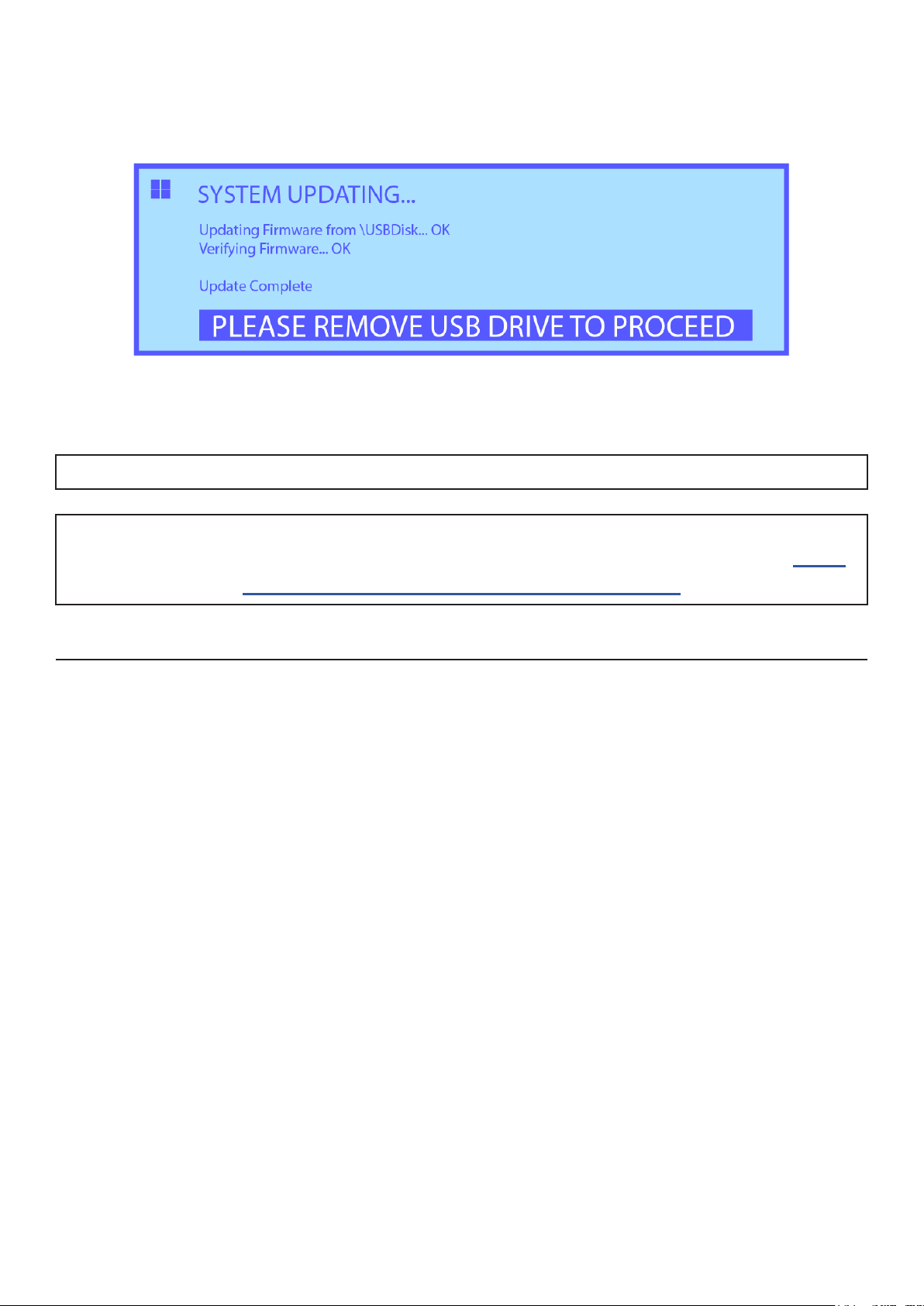
required.
During an update a window indicating progress will appear as in the below image
Upon removal of the USB drive the multimeter will reset
8100 Operation Manual - V1.0.1
Note - It is normal for the screen to turn off during the reset
Note - Please consult the following website prior to applying updates to ensure that your
hardware / low level firmware revision is compatible prior to performing an update - http://
support.transmille.com/solution/articles/9000143946
REGIONAL SETTINGS
The REGIONAL OPTIONS menu enables configuration of the display language of the
multimeter as well as configuration of the Number formatting used on the display
To change Language, select the LANGUAGE option from the menu and then select the desired
language from the list of available languages. The multimeter will update the language
Note - After changing the language the multimeter will need to be reset for all menus to update
There are 3 numerical display formats available :
• 0.000,000,00
• 0.000 000 00
• 0,000 000 00
To change the display format, select the SET DISPLAY FORMAT menu option and then select
the desired formatting from the list.
Page 26
www.transmille.com

8100 Operation Manual - V1.0.1
REMOTE INTERFACE SETTINGS
The REMOTE INTERFACE menu option provides access to the remote interface menu.
Within this menu the multimeter GPIB address can be changed. To change the GPIB address,
select the menu item and then enter the new GPIB address via the numerical keyboard entry window.
On pressing ENTER a confirmation message will appear to confirming that the GPIB address has been
changed.
SCREEN SAVER TIMEOUT
The SCREEN SAVER TIMEOUT menu option provides access to the available screen saver
timeout period. To change the screen saver timeout, select a new option from the list and select the
menu item.
SOUND
The SOUND menu option provides access to the Sound menu. In this menu the Key Beep and
Reading Beep can be enabled or disabled.
SYSTEM PASSWORD
The SYSTEM PASSWORD menu allows users to update the system password.
The system password can consist of Letters and Numbers.
To set a new password, select the menu item and enter the new password using the on screen
keyboard. On pressing the ENTER soft key a confirmation message will appear confirming that the
system password was changed
Note - If the system password is forgotten Transmille can be contacted at support@
transmille.com to request a master password which can be used to reset the user password back
to default
Calibration Menu
The CALIBRATION MENU allows access to the calibration functions of the unit to perform
adjustments.
CALIBRATION MODE
This menu option provides two purposes. Firstly it provides the option to either ENTER or
EXIT calibration mode, allowing or preventing adjustments from being made. The second function is
www.transmille.com
Page 27
8100 Operation Manual - V1.0.1
to indicate the current state of calibration mode.
If Calibration Mode is ENABLED the menu item will display CALIBRATION MODE [ON],
where as if Calibration Mode is DISABLED the menu item will display CALIBRATION MODE
[OFF]
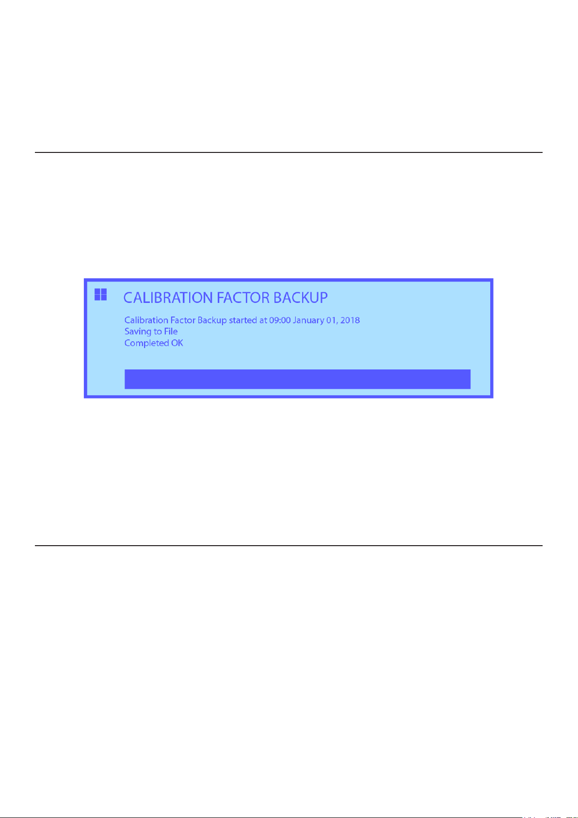
BACKUP CALIBRATION FACTORS
This menu item allows the user to backup calibration factors, ideally prior to making
adjustments or after a known good calibration has been performed.
After selecting this menu a message will appear indicating the a backup is currently being
performed
Once the Calibration Factors have been backed up a final message will appear to indicate
success, and then the menu will be accessible again.
Note - During a calibration factor backup the keyboard will be inoperable and the unit will not
respond to commands over the interface
RESTORE CALIBRATION FACTORS
In the event of a miss-adjustment or a desire to return to factory calibration factors is desired,
the RESTORE CALIBRATION FACTORS menu provides access to a list of all previously stored
calibrations.
Select the desired backup from the list and press SELECT.
The unit will then restore calibration factors from the selected backup.
Page 28
www.transmille.com

8100 Operation Manual - V1.0.1
Display Element Conguration Menu
The Display Element Configuration menu allows the selection of up to 4 Display Elements to
be displayed on the screen simultaneously through selection of the desired elements
Presently active Display Elements are indicated with “>>” in front of the menu item
To enable a display element, navigate and the desired menu item. The desired option will have
“>>” appended to the front to indicate that this Element is now active.
To disable a display element, select a menu item with “>>” in the name. The “>>” will be
removed and the element de-activated.
A maximum of 4 Elements can be configured at any one time, if more than 4 are selected an
error message will appear when selecting the 5th.
Further information regarding the Display Elements functionality can be found on Page 11
www.transmille.com
Page 29
 Loading...