

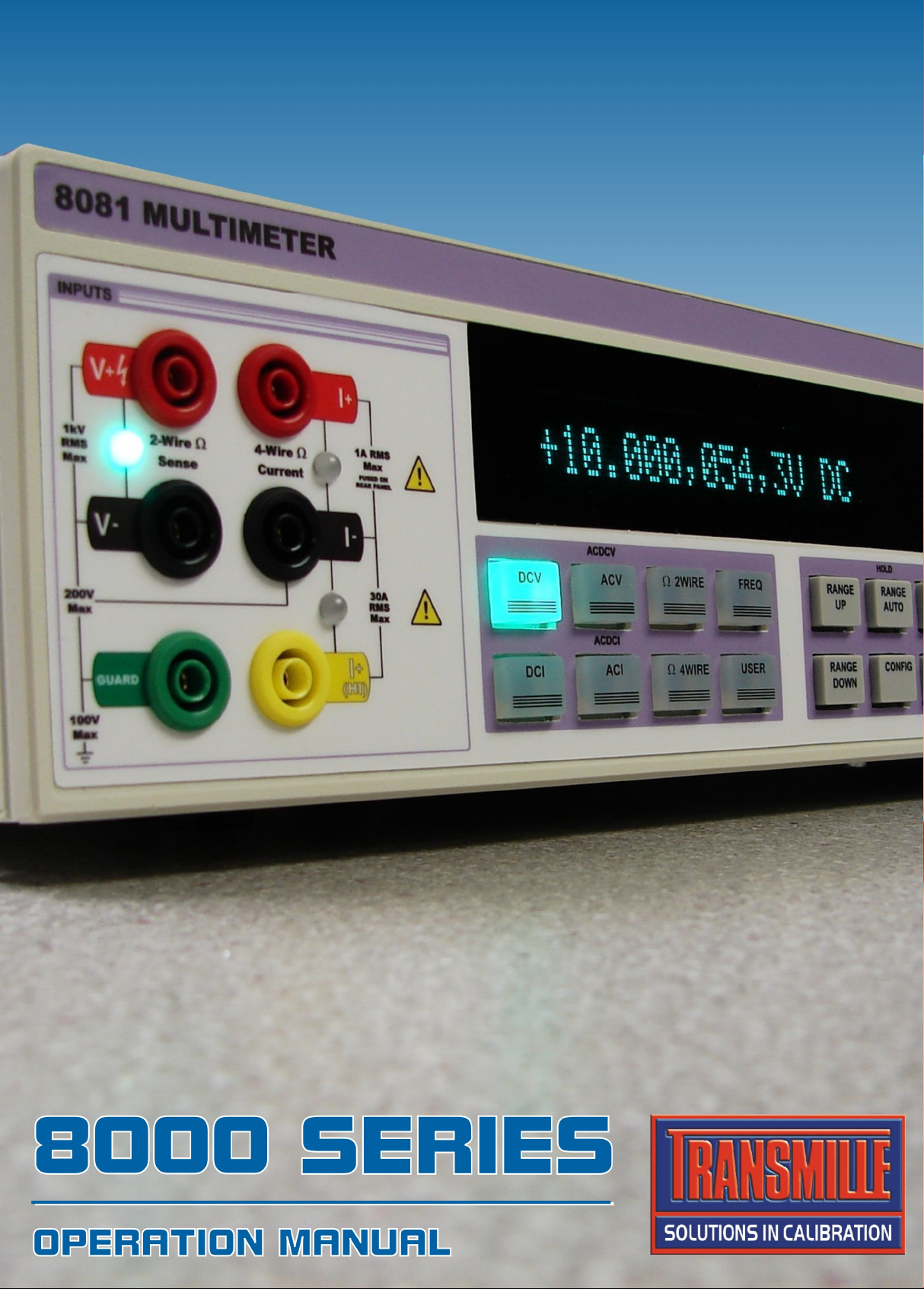

8000 Series
Precision Digital Multimeter
Operation Manual
Version 4.20 : April 2010
All product names are trademarks of their respective companies

8000 SERIES OPERATION MANUAL
IMPORTANT NOTICE
THIS PRODUCT
WILL
REQUIRE AN
UNLOCK CODE
AFTER THE EVALUATION
PERIOD HAS EXPIRED.
(60 Days After Invoice Date)
AFTER THE EVALUATION PERIOD HAS EXPIRED THE OPERATION
OF THE PRODUCT IS LOCKED AND THE DISPLAY SHOWS A
NUMBER WHICH MUST BE QUOTED TO TRANSMILLE TO RECEIVE
THE UNLOCK CODE
THE UNLOCK CODE IS AVAILALBLE
FROM TRANSMILLE
ONLY AFTER PAYMENT
HAS BEEN RECEIVED.
(This code is only entered once in the life of the instrument.)
Please contact Transmille or use the form in the
back of the manual to obtain the code.
Transmille Ltd.
Staplehurst , Kent.
Tel: 44 (0)1580 890700 : Fax 44 (0)1580 890711
EMail: sales@transmille.com
TRANSMILLE LTD. Page 2

8000 SERIES OPERATION MANUAL
DECLARATION OF CONFORMITY
Manufacturer’s Name: Transmille Ltd.
Manufacturer’s Address: Unit 4, Select Business Centre
Lodge Road
Staplehurst
TN12 0QW
Declares, that the product
Product Name: Multimeter
Model Number: 8071 / 8081
Product Options: This declaration covers all options of the above product(s)
Conforms with the following European Directives:
The product herewith complies with the requirements of the Low Voltage Directive 73/73EEC
and the EMC Directive 89/336/EEC (including 93/68/EEC) and carries the CE Marking
accordingly
Conforms with the following product standards:
EMC
EN 61326-1:1997+A1:1998 • EN55011:1991 (Group 1 : Class A)
Standard Limit
IEC 61000-4-2:1995+A1:1998 / EN 61000-4-2:1995 4kV CD, 8kV AD
IEC 61000-4-3:1995 / EN 61000-4-3:1995 3 V/m, 80-1000 MHz
IEC 61000-4-4:1995 / EN 61000-4-4:1995 0.5kV signal lines, 1kV power lines
IEC 61000-4-5:1995 / EN 61000-4-5:1995 0.5kV line-line, 1kV line-ground
IEC 61000-4-6:1996 / EN 61000-4-6:1996 3V, 0.15-80 MHz / cycle, 100%
IEC 61000-4-11:1994 / EN 61000-4-11:1994 Dips: 30% 10ms; 60% 100ms
Interrupt > 95%@5000ms
Date : 27/02/2009
Revision No: 1.00
Managing Director
TRANSMILLE LTD. Page 3

8000 SERIES OPERATION MANUAL
TABLE OF CONTENTS
8000 SERIES MULTIMETER INTRODUCTION....................................................................................6
MAIN FEATURES...................................................................................................................................6
ACCURACY AND FUNCTIONALITY ...........................................................................................................7
MULTI PRODUCT MULTIMETER...............................................................................................................7
EXPANDABLE RANGE OF PRESSURE MODULES ......................................................................................7
MULTI INTERFACE SUPPORT..................................................................................................................8
PREPARING THE MULTIMETER FOR USE........................................................................................9
INITIAL INSPECTION...............................................................................................................................9
LIFTING AND CARRYING THE MULTIMETER ..............................................................................................9
POSITIONING THE MULTIMETER. ..........................................................................................................10
REAR PANEL CONNECTIONS AND CONTROLS........................................................................................11
SETTING AND CHECKING THE LINE VOLTAGE. .......................................................................................12
POWER LINE INLET FUSE AND RATING..................................................................................................12
CONNECTING TO A COMPUTER......................................................................................................13
POWERING UP THE MULTIMETER...................................................................................................15
OUTPUT CONNECTIONS...................................................................................................................16
INPUT OVERLOADS .............................................................................................................................17
SAFETY WARNINGS ............................................................................................................................18
INTRODUCTION TO OPERATION............................................................................................................18
CONTROLS & FUNCTIONS ...................................................................................................................19
PREPARING THE MULTIMETER FOR USE...............................................................................................20
CONNECTIONS FOR VOLTAGE MEASUREMENT TO 1KV..........................................................................21
CONNECTIONS FOR LOW CURRENT MEASUREMENT TO 1A....................................................................21
CONNECTIONS FOR LOW CURRENT MEASUREMENT TO 30A..................................................................21
CONNECTIONS FOR 2 WIRE RESISTANCE MEASUREMENT.....................................................................22
CONNECTIONS FOR 4 WIRE RESISTANCE MEASUREMENT.....................................................................22
ELECTROMETER INPUT : HIGH RESISTANCE MEASUREMENT .................................................................23
ELECTROMETER INPUT : LOW CURRENT MEASUREMENT ......................................................................23
FRONT PANEL CONTROLS AND INDICATORS..............................................................................24
FRONT PANEL SECTIONS ....................................................................................................................24
INPUT TERMINALS & INDICATOR LEDS.................................................................................................24
FUNCTION KEYS .................................................................................................................................25
RANGE & READBACK CONTROLS.........................................................................................................25
INPUT & MENU CONTROLS..................................................................................................................25
MENU DIAL.........................................................................................................................................26
ELECTROMETER I/O TERMINALS..........................................................................................................26
FRONT PANEL KEYBOARD....................................................................................................................26
DUAL DISPLAY....................................................................................................................................27
OPERATING THE MULTIMETER .......................................................................................................28
SELECTING A RANGE ..........................................................................................................................28
SETTINGS MENU MAP.........................................................................................................................29
SETTINGS MENU DESCRIPTIONS..........................................................................................................30
CONFIGURATION MENU MAP ...............................................................................................................31
CONFIGURATION MENU DESCRIPTIONS................................................................................................32
USER MENU MAP (PART 1).................................................................................................................33
USER MENU MAP(PART 2)..................................................................................................................34
USER MENU DESCRIPTIONS................................................................................................................35
TRANSMILLE LTD. Page 4

8000 SERIES OPERATION MANUAL
USING THE 8081 – BEST MEASUREMENT PRACTICE. .................................................................36
Nulling or Zero .............................................................................................................................36
Zeroing the Voltage ranges. ........................................................................................................36
Understanding thermal EMF voltages. ........................................................................................37
Zeroing Current Ranges ..............................................................................................................38
2-Wire null method (all ranges) [Except Electrometer]................................................................38
4-Wire null methods (10kOhm and below)..................................................................................38
8000 SERIES FUNCTIONS .................................................................................................................39
DC VOLTAGE .....................................................................................................................................39
AC VOLTAGE .....................................................................................................................................40
DC CURRENT.....................................................................................................................................41
DC CURRENT (ELECTROMETER MODE) (OPTION)................................................................................42
AC CURRENT.....................................................................................................................................43
2-WIRE RESISTANCE ..........................................................................................................................44
2-WIRE RESISTANCE (ELECTROMETER MODE) (OPTION)......................................................................45
4-WIRE RESISTANCE ..........................................................................................................................46
FREQUENCY.......................................................................................................................................47
THERMOCOUPLE MEASUREMENT : CONNECTION DIAGRAMS (OPTION) ..................................................48
THERMOCOUPLE MEASUREMENT : MULTIMETER SETUP (OPTION).........................................................49
PRT MEASUREMENT : CONNECTION DIAGRAMS (OPTION)....................................................................50
PRT MEASUREMENT : MULTIMETER SETUP (OPTION)..........................................................................51
GUIDE TO SETTING UP A PRT PROBE...................................................................................................52
PRESSURE MEASUREMENT : CONNECTION DIAGRAM (OPTION).............................................................53
PRESSURE MEASUREMENT : MULTIMETER SETUP (OPTION).................................................................54
SHUNT MEASUREMENT : CONNECTION DIAGRAM (OPTION)...................................................................55
SHUNT MEASUREMENT : MULTIMETER SETUP (OPTION).......................................................................56
DC POWER / DUAL INPUT V/30A (OPTION) .........................................................................................57
USING THE MATH FUNCTIONS..............................................................................................................58
REMOTE PROGRAMMING.................................................................................................................59
PROGRAMMING COMMANDS OVERVIEW...............................................................................................60
COMMAND RESPONSE CODES.............................................................................................................60
SCPI.................................................................................................................................................61
GENERAL ...........................................................................................................................................62
SETUP ...............................................................................................................................................63
CALIBRATION......................................................................................................................................64
CALIBRATION.....................................................................................................................................65
CALIBRATION OVERVIEW.....................................................................................................................65
ENTERING CALIBRATION MODE ...........................................................................................................65
EXAMPLE 1 : DC VOLTAGE 10V RANGE ..............................................................................................67
EXAMPLE 2 : AC VOLTAGE 10V RANGE ..............................................................................................67
GENERAL MAINTENANCE ................................................................................................................68
ELECTRICAL SAFETY TESTS ................................................................................................................68
CLEANING THE EXTERNAL CASE...........................................................................................................68
GUARANTEE AND SERVICE...................................................................................................................69
TRANSMILLE LTD. Page 5

8000 SERIES OPERATION MANUAL
8000 Series Multimeter Introduction
The 8000 series range of multimeters offer maximised capabilities from a highly accurate 4ppm /
9ppm advanced design. Utilising the precision electronics to their fullest extent, the 8000 Series
provides high performance core functionality combined with advanced operation modes in a single
instrument.
Main Features
AC/DC Volts to 1025V
AC/DC Current to 30 Amps
DC Low Current Measurement (Option)
2 and 4 Wire Resistance
High Resistance Measurement to 1 TOhm (Option)
Frequency
Temperature Measurement (PRT / ITS90 / SPRT Co-efficient storage modes) (Option)
Pressure Module Support : Measurement to 100Bar (Option)
RS232 Serial Interface
USB Interface
GPIB (IEEE488)
Ethernet (LAN) Interface
TRANSMILLE LTD. Page 6

8000 SERIES OPERATION MANUAL
Accuracy And Functionality
The 8000 Series multimeters are available in 2 accuracy grades - the 8081 / 8080 4ppm model and
the 8071 of 9ppm model. The appearance of these units is the same, however the model is indicated
on the front & rear panel and shown on the display on power up.
Multi Product Multimeter
Designed to provide an accurate cost effective portable instrument for the calibration of a wide range
of signal sources including pressure, temperature and more. The 8000 series multimeter is equally
suitable for use in the standards laboratory or for on site calibration work with a fast warm up time
combined with low weight and optional soft / hard carry cases. The multi – interface design allows
direct connection to desktop or laptop PCs via RS232, USB, GPIB or Ethernet.
Expandable Range of Pressure Modules
A range of pressure modules are available for support of pressure measurement
(optional pressure hand pump also available) – see www.transmille.com
for further information.
TRANSMILLE LTD. Page 7

8000 SERIES OPERATION MANUAL
Multi Interface Support
All functions and ranges of the series 8000 multimeter are fully programmable over the multiple
interfaces. The support of RS232, USB and Ethernet saves the cost of fitting GPIB cards to the PC,
and also allows easy connection to portable PC’s, reducing the set up time for on site calibration.
GPIB is also available where use of this type of interface is already implemented.
TRANSMILLE LTD. Page 8
8000 SERIES OPERATION MANUAL
Preparing the Multimeter For Use
Initial Inspection
After shipment the multimeter should be inspected for any signs of external damage. Should external
damage be found contact the carrier immediately. Do not connect a damaged instrument to the line
power as this may result in internal damage. Please keep the original box as this can be used when
returning the multimeter for service and recalibration.
Lifting and carrying the Multimeter
The multimeter can be carried easily by one person by supporting from underneath (Note : observe
all normal practices for health and safety when carrying). A custom carry case with shoulder strap is
available if the multimeter is to be regularly transported - see options list. The multimeter should
always be placed down on a firm flat surface on its base feet. Avoid knocking or banging the
multimeter and always place down smoothly.
WARNING
DO NOT DROP THE MULTIMETER AS THIS MAY CAUSE INTERNAL DAMAGE.
TRANSMILLE LTD. Page 9
8000 SERIES OPERATION MANUAL
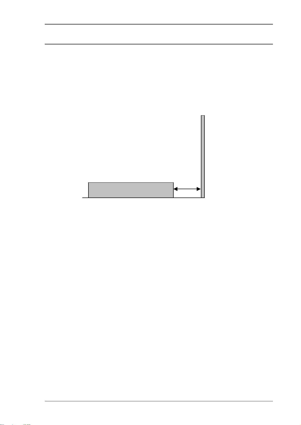
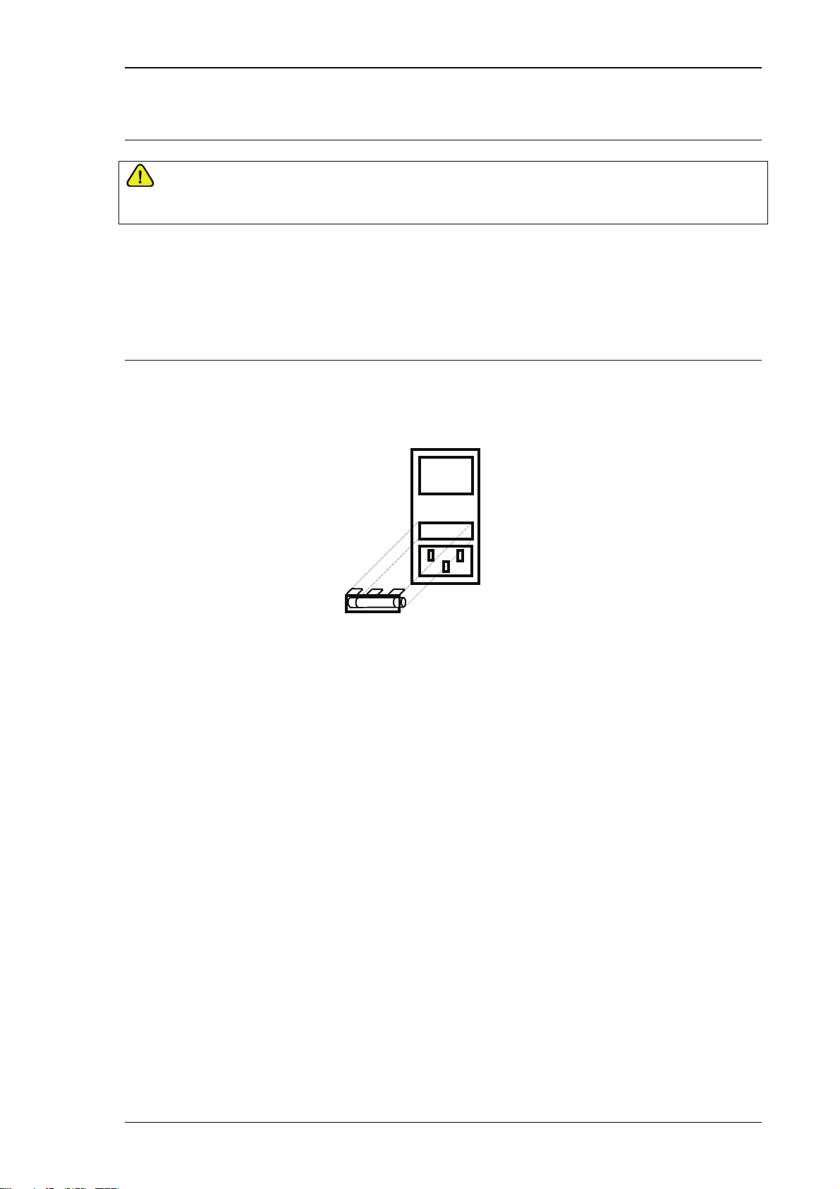
Positioning the Multimeter.
The multimeter can be used free standing on a bench or mounted in a standard 19” rack enclosure.
The multimeter can be operated at any angle, the two front feet have tilt legs for bench operation.
A 2” (5cm) space behind the instrument is also required for line and interface connections.
Minimum 2” (5cm) Clearance
TRANSMILLE LTD. Page 10
8000 SERIES OPERATION MANUAL
(Op
)
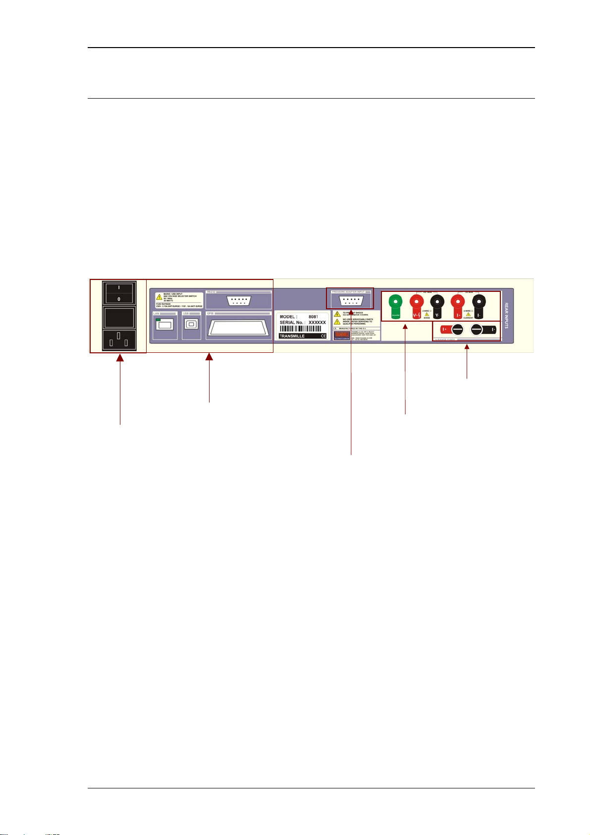
Rear Panel Connections and controls
Connections on the rear panel are for Line Power via a 3 Pin IEC connector incorporating the Line
fuse and on-off switch -note the mains inlet is filtered.
The multiple interface connections are available including RS232, USB, GPIB and Ethernet (LAN)
These interfaces are optically isolated from the multimeter intput.
On 8081 units a set of rear panel terminals are fitted as standard, including voltage, current (to 1A)
and a guard terminal. The 1 A range + and – fuses are located below the current terminals (1A Q.B.).
This set of rear terminals is an option on other models
Power Switch /
Input Fuse / Inlet
Interface Connections
RS232 / Ethernet / GPIB
Rear Panel Input
Terminals
Pressure Adapter
Input (Optional)
1A Range Fuses
tional
TRANSMILLE LTD. Page 11
8000 SERIES OPERATION MANUAL
Setting and checking the Line Voltage.
WARNING
THE LINE POWER CORD MUST HAVE AN EARTH CONDUCTOR TO AVOID RISK
OF SHOCK. THIS INSTRUMENT MUST BE CORRECTLY EARTHED.
The multimeter has been designed to work from either 100-120 Volt line supply or 200 - 240 Volt line
supply. Check Supply voltage as marked on the rear panel before connecting to power line.
Connecting the multimeter to the wrong supply will cause internal damage to the instrument.
Power Line Inlet Fuse and rating
The Power line inlet fuse is located directly above the power inlet. The correct fuse for is
1A Anti-surge for 230V operation and 1A Anti surge for 110V Operation
FUSE
TRANSMILLE LTD. Page 12
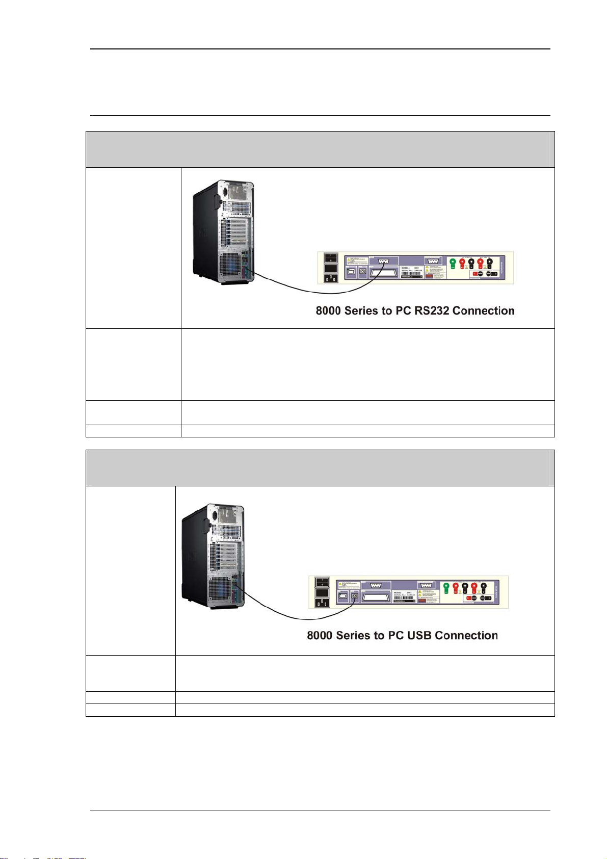
Connecting to a computer
RS232 Interface
Connection
Configuration
Cable Type Male to Female Serial Cable
Software Driver N/A
USB Interface
Connection
BAUD RATE : 9600
PARITY : NONE
DATA BITS : 8
STOP BITS : 1
Straight Though Pin Connection (Not Null MODEM)
8000 SERIES OPERATION MANUAL
Configuration N/A
Cable Type USB ‘A’ Type connector to USB ‘B’ Connector
Software Driver FTDI USB Driver (Supplied)
TRANSMILLE LTD. Page 13

Ethernet (LAN) Interface
Connection
8000 SERIES OPERATION MANUAL
Configuration 8000 Series Menu Setup :
Press MENU
Press Ä until ETHERNET is displayed
Press Æ
*For automatic IP Address (DHCP Host required*) Select ENABLE DHCP
*To set a manual IP Address Select SET IP and enter IP Address in
xxx.xxx.xxx.xxx format.
* For further information consult your network administrator.
Cable Type 100BaseT Ethernet Cable (Standard Network Cable)
Software Driver N/A
GPIB Interface
Connection
Configuration N/A
Cable Type GPIB Interface Cable
Software Driver National Instruments GPIB Device Driver or Similar (Card Specific)
TRANSMILLE LTD. Page 14

8000 SERIES OPERATION MANUAL
Powering up the multimeter
After connecting line power, the multimeter can be switched on with the line power switch above the
mains inlet socket on the rear panel.
The front panel displays will illuminate and indicate if the instrument is in evaluation mode for a
period of 5 seconds, giving the user a chance to unlock the instrument. The start-up sequence will
operate internal circuits indicating initial power up during which time the processor performs a self
test of the instrument - the display will then switch to measurement display mode.
Transmille Ltd.
Æ
Evaluation 60 days
Æ
0.0000mV D.C.
Allow the multimeter to warm up for 3 hours to obtain 90% of full specifications.
TRANSMILLE LTD. Page 15
8000 SERIES OPERATION MANUAL
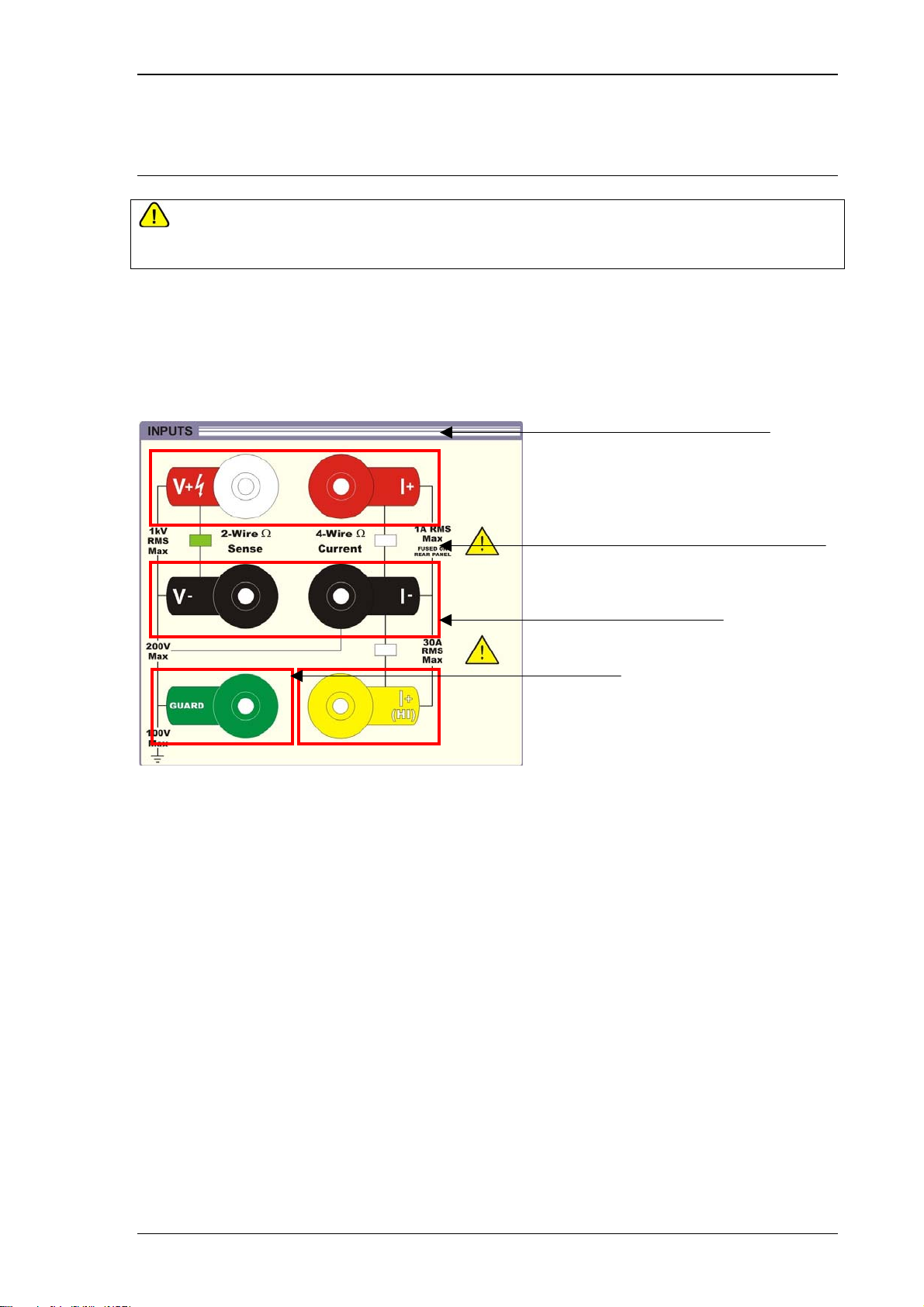
V
Output Connections
WARNING
THE LINE POWER CORD MUST HAVE AN EARTH CONDUCTOR TO AVOID RISK
OF SHOCK. THIS INSTRUMENT MUST BE CORRECTLY EARTHED.
Input sockets are all 4mm safety type, the voltage pairs contacts are low thermal gold plated for
minimum thermal EMF.
oltage / 2-Wire Resistance
Current (to 1A) / 4-Wire Resistance
High Current (to 30A)
Guard
TRANSMILLE LTD. Page 16
8000 SERIES OPERATION MANUAL
It is recommended that the voltage and low current leads be high quality screened cable with gold
plated 4mm plugs fitted. The cable must be able to withstand 1025 volts AC and have an insulation
resistance greater than 1 TOhm to avoid introducing any shunting effect on the high resistance
ranges.
Poor quality test leads will introduce noise, thermal emf and leakage errors on low voltage & current
ranges and also unstable readings on resistance and capacitance outputs (see measurement
techniques ). Special test leads are available from Transmille, see accessories.
WARNING
OBSERVE ALL MAXIMUM INPUT RATINGS WHEN PERFORMING MEASUREMENTS
Input Overloads
If the multimeter is unable to measure the input due to over range, the display will indicate
OVER-RANGE .
TRANSMILLE LTD. Page 17

8000 SERIES OPERATION MANUAL
Operation
Safety Warnings
WARNING :
THE INFORMATION IN THIS SECTION IS INTENDED ONLY FOR QUALIFIED PERSONNEL. THE
USER MUST AT ALL TIMES BE ADEQUATELY PROTECTED FROM ELECTRIC SHOCK.
QUALIFIED PERSONNEL MUST ENSURE THAT OPERATORS OF THE EQUIPMENT ARE
ADEQUATELY INSULATED FROM CONNECTION POINTS.
A SOFT CARRY-CASE AND A HARD TRANSIT CASE ARE AVAILABLE FOR REGULAR
TRANSPORTATION OF THE MULTIMETER.
Introduction to Operation
All functions of the 8000 Series Multimeter can be controlled from the front panel or controlled
remotely by a computer over the remote interface. The front panel controls are ‘locked out’, but local
control may be resumed by selecting the LOCAL key - it must be remembered that this action may
disrupt any computer program controlling the multimeter.
TRANSMILLE LTD. Page 18
8000 SERIES OPERATION MANUAL
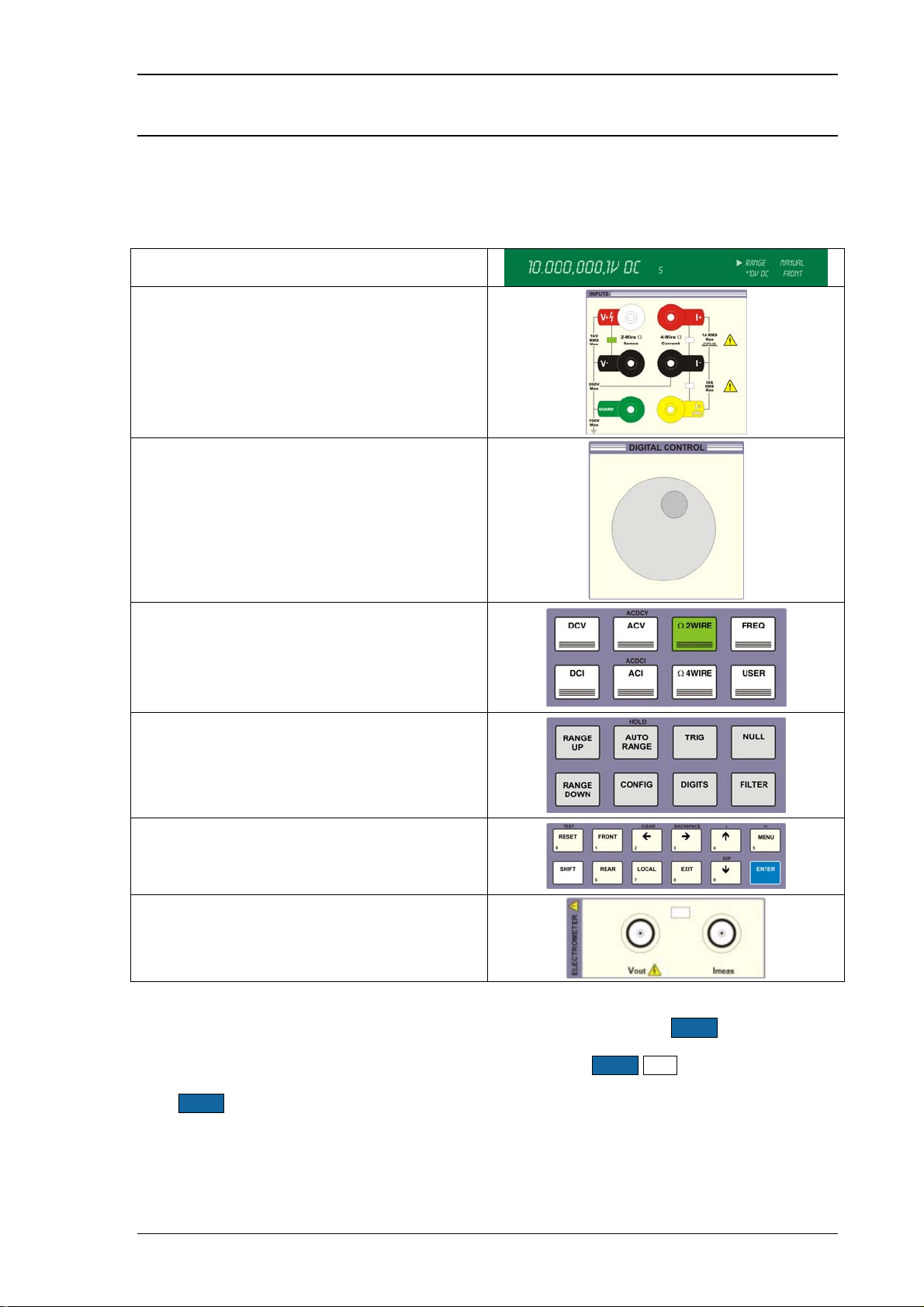
Controls & Functions
To familiarise yourself with the 8000 Series multimeters, it is advised to learn a selection of the basic
operations of the front panel controls before use.
The front panel consists of the following sections :
Dual Display
Input terminals and Indicator LEDs
Digital Control Dial
Function Keys
Range & Readback Controls
Input & Menu Controls
Electrometer I/O Terminals
The front panel keys are grouped into related sections, with certain keys providing ‘shift’ functions as
printed above the relevant key. To perform a shifted function, simply click the SHIFT key which will
illuminate in blue. Press one of the keys with the required function labelled above it and this function
will be selected. For example to select the ACDCV function press SHIFT ACV.
If the SHIFT button is pressed by mistake, simple press it again to de-select it.
TRANSMILLE LTD. Page 19

8000 SERIES OPERATION MANUAL
Preparing the Multimeter For Use
The multimeter front panel displays and function buttons will illuminate, with the function selected
remaining lit once the start up sequence is complete.
If the multimeter does not power up as expected check the following :
Check AC power is connected to the multimeter
Ensure AC power is supplied via the mains lead and the Off/ On switch is switch to the I (on)
position
Verify the line voltage selection on the rear power inlet is correct
Check voltage selector on the mains inlet
Check the line input fuse is OK and does not require replacement.
This can be performed using the continuity function on a basic hand held
multimeter.
TRANSMILLE LTD. Page 20
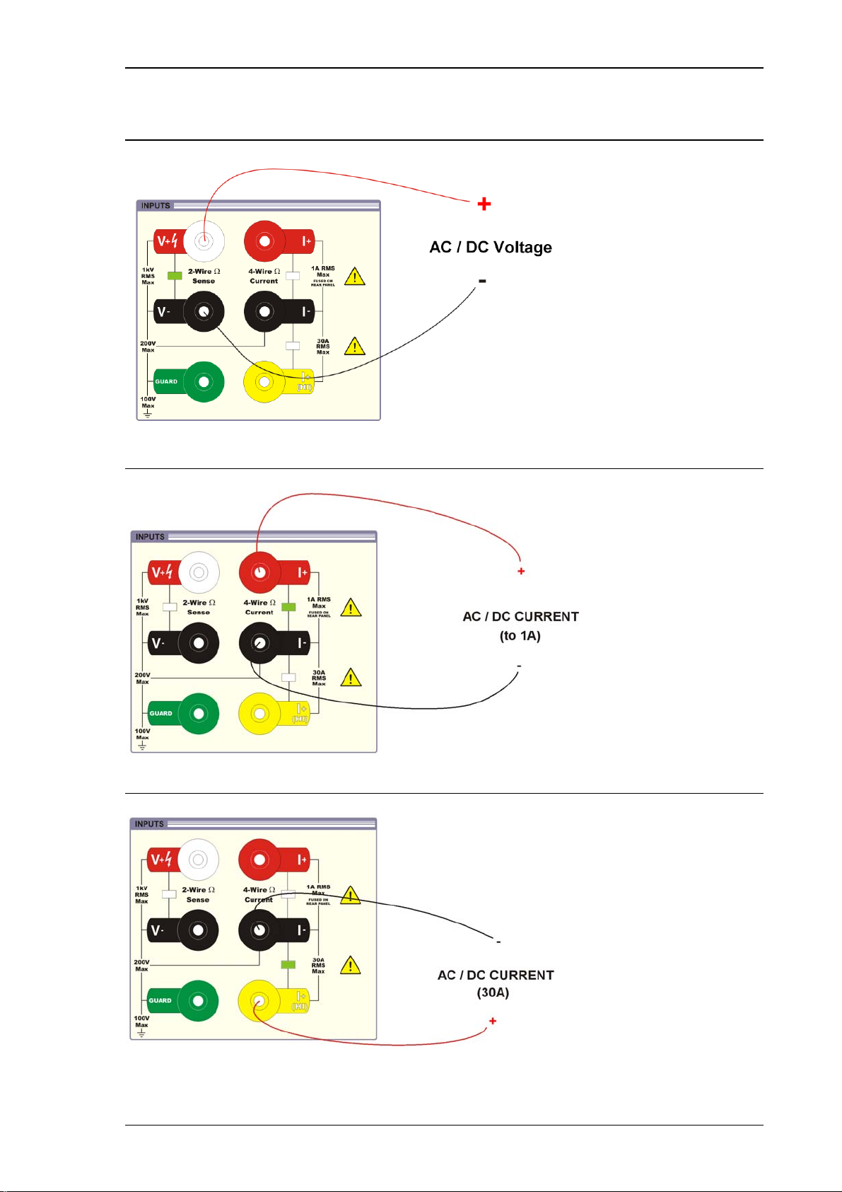
Connections for Voltage Measurement to 1kV
8000 SERIES OPERATION MANUAL
Connections for Low Current Measurement to 1A
Connections for Low Current Measurement to 30A
TRANSMILLE LTD. Page 21
 Loading...