

Transmille 4000 Specifications
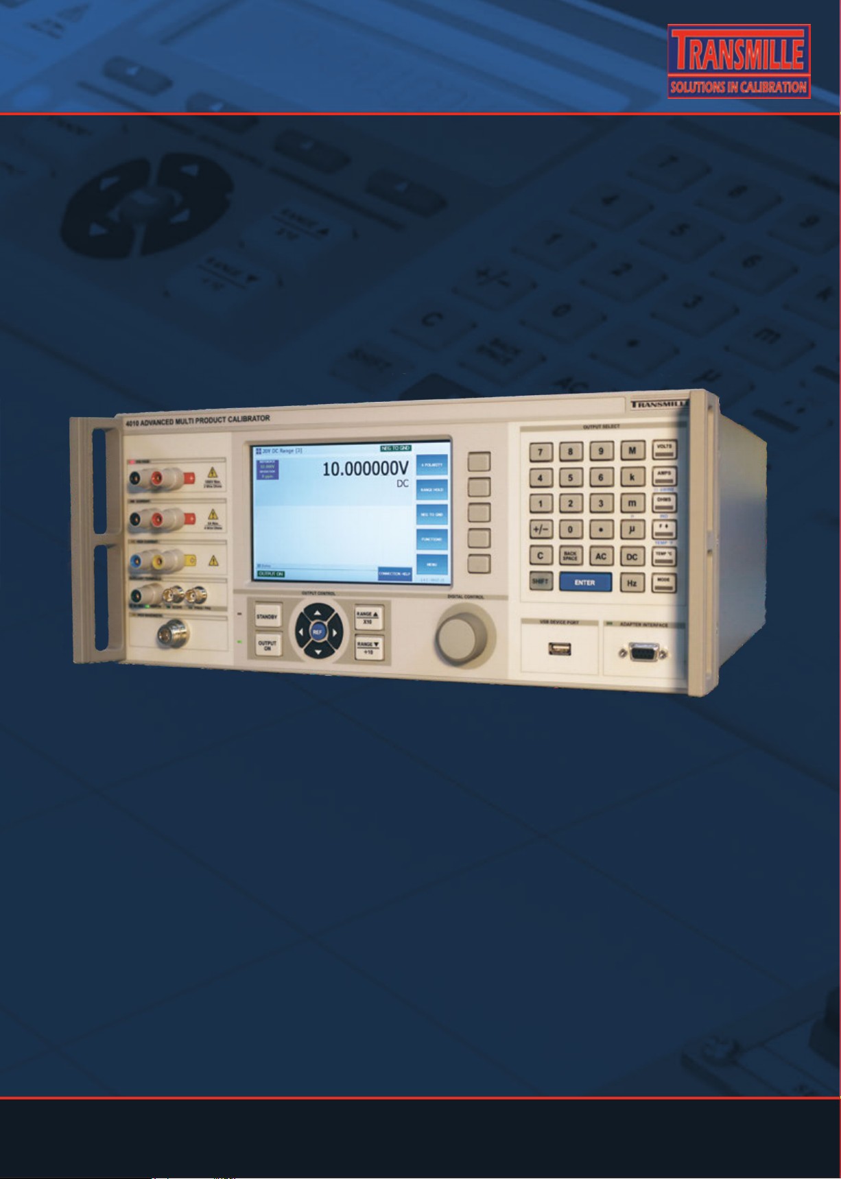
TRANSMILLE 4010
ADVANCED MULTIPRODUCT
CALIBRATOR
EXTENDED SPECIFICATIONS
www. transmille.com
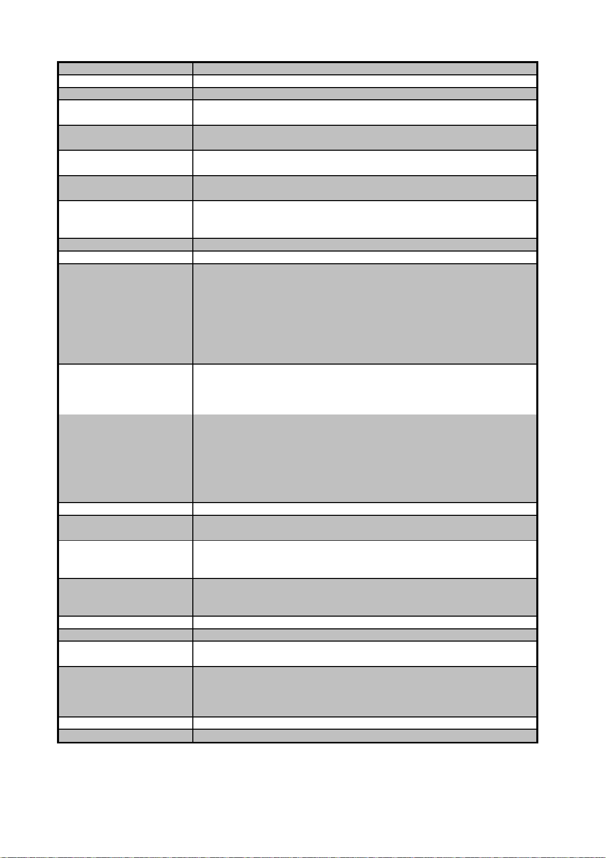
4010 EXTENDED SPECIFICATIONS General Specifications TRANSMILLE LTD
Due to continuous development specifications may be subject to change.
4010 Extended Specifications
General Specifications : V1.4
Case Colour Grey
Warm Up Time Double the time since last used up to 20 minutes maximum
Standard Interfaces
USB
Optional Interfaces GPIB (IEEE-488) : RS232
Temperature Performance Storage : -5°C to +60°C
Operation : 0°C to +50°C
Relative Humidity Operation : <80% to 30°C, <70% to 40°C, <40% to 50°C
Storage : <95%, non-condensing
Altitude Operation : 3000m (10,000ft) Maximum
Transit : 12000m (40,000ft) Maximum
EMC & Safety The calibrator line input plug must be earthed
See D.O.C for full details
Line Power Line Voltage Selectable : 110V / 230V (100V Option Available)
Line Frequency : 50Hz to 60Hz
Line Voltage Variation : -6% +10%
Power Consumption 28 Watts (Standby) 200 Watts (Maximum)
Low Analogue Isolation 100V
Front Panel Connections
Voltage / 2 Wire Resistance 1x Black : 1x Red 4mm Binding Posts
Low Current (<=2A)
1x Black : 1x Red 4mm Binding Posts
High current (>2A) 1x Blue : 1x Yellow 4mm Binding Posts
Earth Connection 1x Green 4mm Binding Posts
Oscilloscope Functions 2x BNC terminal
Adapter Interface 1x Female 'D' type socket
USB Interface 1x Female 'B' type socket
High Bandwidth Output 1 x Female Type 'N' socket
Display Information Type Touchscreen LCD
Viewing Area 7"
Resolution 800 * 480
Backlight Type LED
Indicators Voltage / Current / High Current Red LED (left of terminals)
Negative to ground Green LED (left of Earth terminal)
Oscilloscope Green LED (right of BNC Connector)
RF Frequency Output Green LED (right of Type N Connector)
Standby Indicator Red LED (left of Standby Key )
Output Indicator Green LED (left of Operate Key)
Adapter Interface Green LED (right of 'D' type connector)
Keyboard Rubber key
Fuses Mains Inlet 3.15A A/S (240 Volt)
5A A/S (110 Volt operation)
Isolation Outputs are opto-isolated from mains earth and the USB interface
Maximum common mode voltage between earth and the
low terminals 30 Volts ac/dc.
Dimensions & Weights
Calibrator Only 19cm x 43cm x 46cm : 15kgs
Calibrator in Shipping Box 65cm x 56cm x 37cm : 18kgs
Calibrator in Hard Transit case 65cm x 56cm x 26cm : 25kgs
Warranty Period 1 Years (Parts & Labour)
Recommended Service I nt erval 1 Year
Supplied Connections
1x USB Interface Connection
1x Mains Lead
1x Adaptor Connection Lead (if at least one adaptor ordered)
Optional Lead Set Kit 1x Voltage connection lead set
1x Low Current connection lead set
1x High current connection lead set
1x AC connection lead set
Mounting Kit (optional) 4U rack mount kit
www.Transmille.com
Page 1

4010 EXTENDED SPECIFICATIONS Interpreting Specifications TRANSMILLE LTD
Due to continuous development specific ations may be subject to change.
4010 Extended Specifications
Interpreting Specifications : V 1.4
uncertainties.
Interpreting Specifications
Transmille have taken great care over presenting the extended specifications
in a manner that is easy to read while including high levels of details
Transmille specify specifications as both Absolute and Relative Specifciation,
with varying calibration intervals, from 24 Hours to 2 Years
By 'Absolute Uncertainties', this means that all internal components of the
calibrator have been compensated for. This includes stability,
line voltage variations, temperature, humidity as well as the uncertainty of
calibration as performed by Transmille Ltd.
This does NOT include external sources of uncertainty, such as the leads
that are used to connect to the calibrator, and resolution of the UUT
Relative Accuracy' refers to the stablity of the instrment itself, without any
external factors except temperature variation.
During re-calibration, the 'Absolute Uncertainties' should be used for verification
of the instrument. If the calibration laboratory offers better uncertainties
than those offered by Transmille, new uncertainties can be calculated by combining
the relative specification and the new imported uncertainties.
All of Transmilles Absolute uncertainties are presented to 95% confidence, k=2.
This is for ease of use in a 17025 accredited laboratory, where other contributions
will likely also be calculated for k=2, minimising the need for re-calibration of
www.Transmille.com
Page 2
4010 EXTENDED SPECIFICATIONS DCV Specifications TRANSMILLE LTD
Due to continuous development specifications may be subject to change.
4010 Extended Specifications
DCV Specifications : V1.4
1mA
2
20 V 15 + 2
20mA
3
1200V 12 + 240
20mA
3
Noise
4
90 day Rel 180 Day Rel 1 year Rel 2 year Rel
+
+
+
+
+
+
+
+
+
+
Note 1: Allowance must be made for output resistance when driving into a load.
Note 2: Limited by 50 Ohm output impedance.
Note 3 : Internally adjustable from 2mA to 30mA - Factory set to 20mA as standard.
Note 4: Typical RMS noise figures at 50% of full scale, bandwidth 1Hz to 10Hz.
Protection
Resistance
1
24 Hour Stability
0.2 Ohms
0.5 Ohms
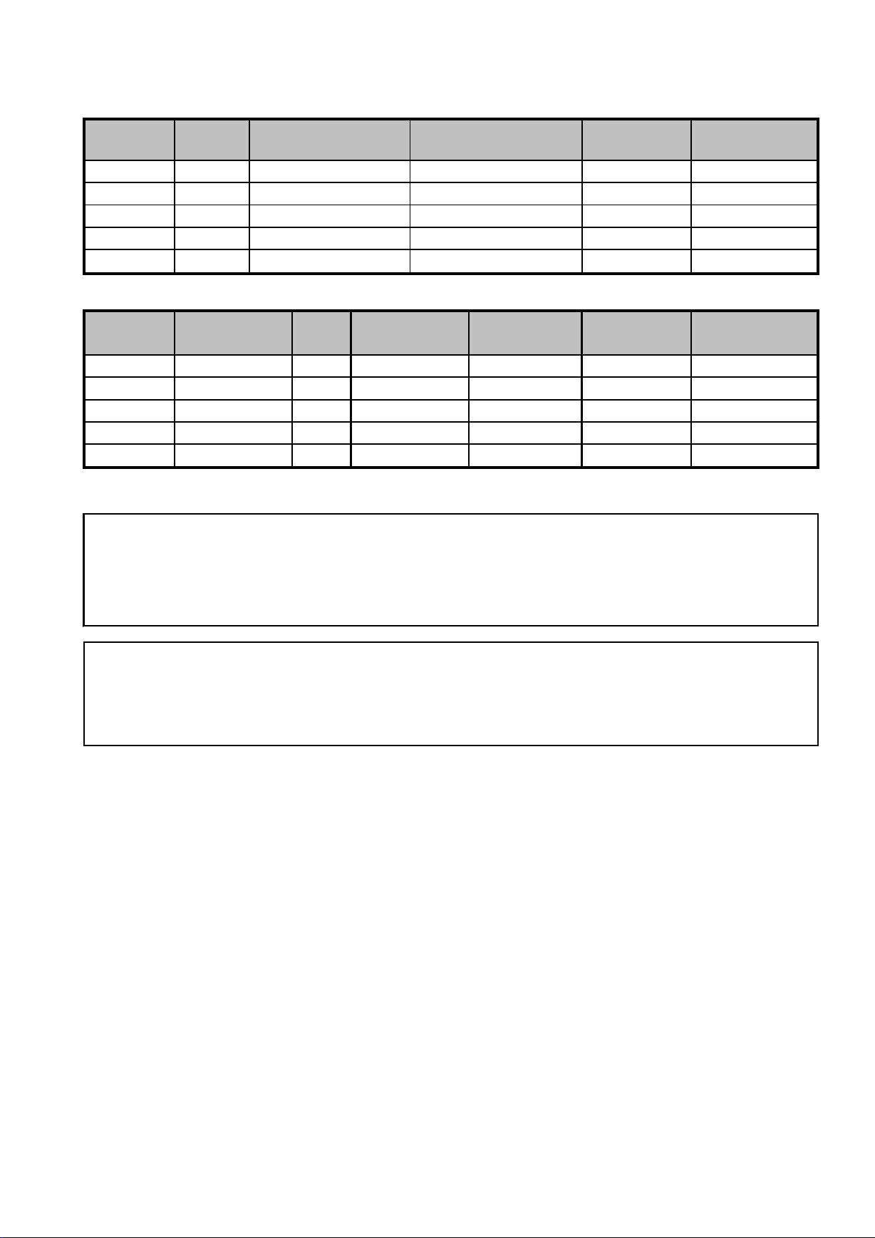
1 year Total Accuracy Specifications at Tcal ±5°C
Range Resolution Max. Burden 1 Year Total
Current ppm set uV
0-202mV 0.01uV
Typical O utput
50 Ohms
0.2-2.02V 0.1uV 50mA 150V 9 + 2.5
2-20.2V 1uV 50mA 150V 8 + 24
0.2 Ohms
20-202V 10uV
200-1025V 100uV
0.7 Ohms
Overload
1200V 12 + 2400
Stability (Accuracy relative to calibration Standards)
Range
ppm Set uV uV ppm Set uV ppm Set uV ppm Set uV ppm Set uV
0-202mV 2 + 1 0.3 9.6 + 2 10.8
0.2-2.02V 2 + 1.2 0.4 5.6 + 2.5 6.3
2-20.2V 2 + 9 3 4.8 + 24 5.4
20-202V 3.5 + 120 40 8 + 240 9
200-1020V 5 + 1100 363 8 + 2400 9
2 12
2.5 7
24 6
240 10
2400 10
2 16.8 + 2.8
2.5 9.8 + 3.5
24 8.4 + 33.6
240 14 + 336
2400 14 + 3360
Notes
For safety the trip is controlled by a fail-safe circuit independant of the processor which shuts the high voltage
output off in the event of an overload.
High Voltage Safety
High voltage output is ramped to allow instrument under test to auto range.
Standby is automatically activated when setting voltages greater than 20V or 200V from a lower voltage
Standby is automatically selected for high voltage (>20V) after 20 minutes on the same setting. This function can be disabled
High voltage (> 20V) output is indicated to user through an audible warning beep.
An external high voltage output/standby control switch is available as an option.
2 Wire output / Remote sensing not available.
Isolation : Floating or grounded selection available as standard.
Maximum floating voltage : 100V
Specifications apply at TCal ± 5°C
Outside this range an allowance of 0.18 x 1 Year Spec. per °C should be added.
www.Transmille.com
Page 3
4010 EXTENDED SPECIFICATIONS DCI Specifications TRANSMILLE LTD
Due to continuous development specifications may be subject to change.
4010 Extended Specifications
DCI Specifications : V1.4
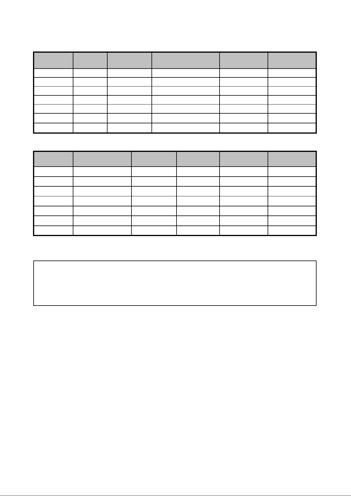
1 year Total Accuracy Specifications at TCal ±5°C
Voltage
Protection % set uA
Stability (Accuracy relative to calibration Standards)
Noise
1
90 Day Rel 180 Day Rel 1 Year Rel 2 Year Rel
0.1-1Hz %Set uA %Set uA %Set uA %Set uA
+
+
+
+
2-20.2A
0.016 + 300 0.018
+
2
0.024 + 450 0.027
+
4.2 Volts
Max. Inductive
Load
4.2 Volts
4.2 Volts
4.2 Volts
1uA
20uA
20uA
180pA
500pA
4nA
40nA
Range Resolution Compliance Overload 1 Year Total
0-202uA 10pA 10mH 150V 0.01 + 0.01
0.2-2.02mA 100pA 10mH 150V 0.005 + 0.03
2-20.2mA 1nA 10mH 150V 0.005 + 0.2
20-202mA 10nA 10mH 150V 0.005 + 2
4.2 Volts
0.2-2.02A 100nA 10mH 150V 0.013 + 30
2-20.2A 1uA 10mH 150V 0.03 + 300
20.2-30A 10uA 10mH 150V 0.05 + 450
3.9 Volts
3.9 Volts
Range
0-202uA 0.006 + 0.01 0.007+0.01 0.008 + 0.01 0.011 + 0.014
0.2-2.02mA 0.0032 + 0.03 0.0036
2-20.2mA 0.0032 + 0.2 0.0036
20-202mA 0.0032 + 2 0.0036
0.2-2.02A 0.0056 + 30 0.006
2
20.2-30A
0.03 0.004 + 0.03 0.006 + 0.042
0.2 0.004 + 0.2 0.006 + 0.28
2 0.004 + 2 0.006 + 2.8
30 0.007 + 30 0.01 + 42
300 0.02 + 300 0.028 + 420
450 0.03 + 450 0.042 + 630
Notes
Note 1 : Typical RMS noise figures at 50% of full scale.
Note 2 : Power & temperature sensor on 30A range - microprocessor monitors & protects from overheating.
Higher resistance loads allow a longer ON period. See graphs 1 and 2 for details.
Note 3 : Specifications apply to loads of less than 10% of the maximum burden voltage.
Note 4: Zero or floor allowance.
Specifications apply at TCal ± 5°C
Outside this range an allowance of 0.18 x 1 Year Spec. per °C should be added.
www.Transmille.com
Page 4
4010 EXTENDED SPECIFICATIONS DCI Specifications TRANSMILLE LTD
Due to continuous development specifications may be subject to change.
4010 Extended Specifications
DCI Specifications : V1.4
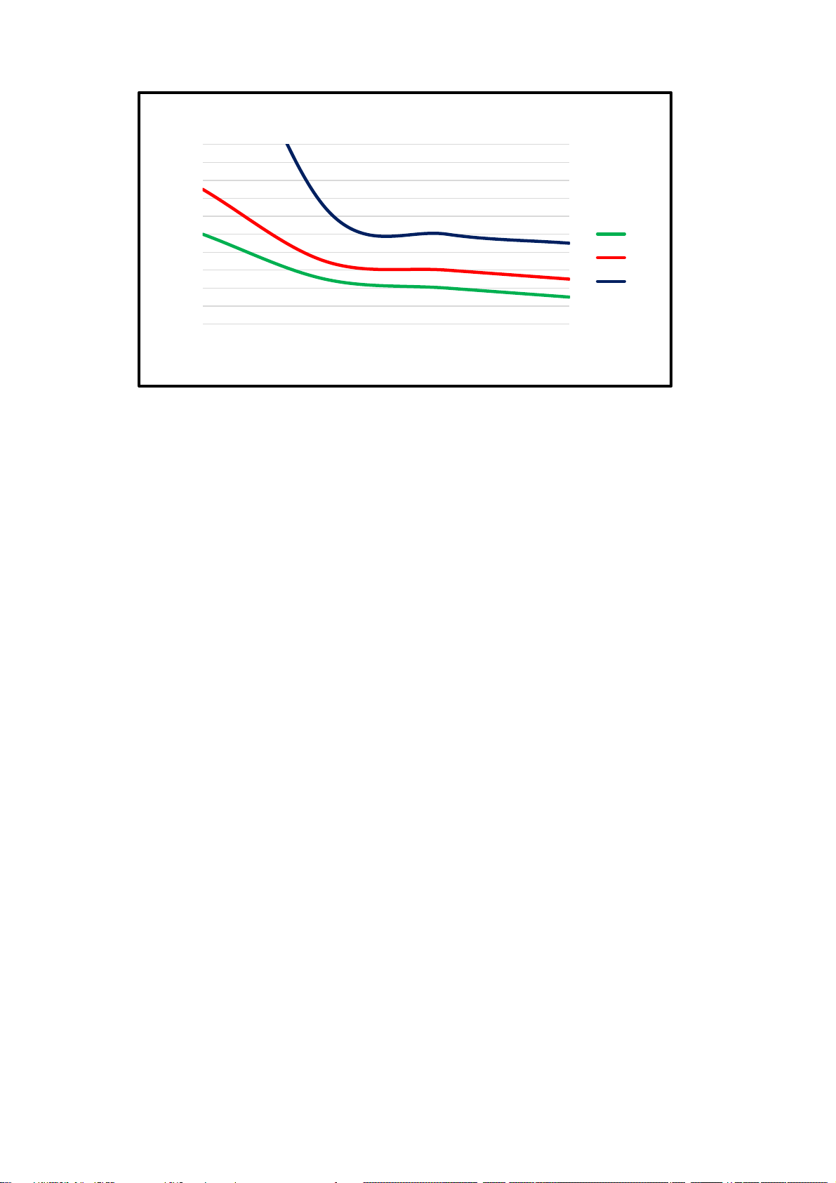
A higher ohmic value load (for example, a 0.1R Shunt) allows greater output time as more heat is dissapated
considerations of self heating of the external load/Uut should be considered due to the power being dissapate
Load
Current Duration of 30A Range into Load
10
9
8
7
6
5
4
3
Time (Minutes)
2
1
0
15 17 19 21 23 25 27 29
Current (Amps)
Measurement Conditions : Ambient Temperature 20'C, Mains Voltage 230V, Mains Frequency 50Hz
Allow at least 7 minutes 'off' period between current output
0.01R
0.03R
0.05R
Shorter periods will reduce the output time availiable.
within the shunt / load. With lower loads more heat is dissapated within the instrument, reducing output
time
Into a 0.1R Load outputs of up to 20A are available for periods of greater than 30 minutes continously,
www.Transmille.com
Page 5
4010 EXTENDED SPECIFICATIONS ACV Specifications TRANSMILLE LTD
Due to continuous development specifications may be subject to change.
4010 Extended Specifications
ACV Specificati ons : V1.4
1 year Total Accuracy Specifications at TCal ±5°C
Resistance % set uV
1mA
1
50 Ohms 20 V 0.0800 + 15
1mA
1
50 Ohms 20 V 0.0160 + 15
1mA
1
50 Ohms 20 V 0.0200 + 28
1mA
1
50 Ohms 20 V 0.1000 + 40
1mA
1
50 Ohms 20 V 0.4000 + 100
20mA
2
0.5 Ohms 1200V 0.0500 + 20mV
15mA
2
0.5 Ohms 1200V 0.0150 + 12mV
15mA
2
0.5 Ohms 1200V 0.0200 + 16mV
2mA
2
0.5 Ohms 1200V 0.0300 + 30mV
2mA
2
0.2000 + 50mV
20mA
2
0.7 Ohms 1200V 0.0550 + 200mV
15mA
2
0.7 Ohms 1200V 0.0200 + 60mV
2mA
2
0.7 Ohms 1200V 0.0250 + 120mV
2mA
2
0.7 Ohms 1200V 0.0300 + 200mV
All specifications apply from 10% of full scale.
5
AC Frequency Accuracy : 30ppm
1Hz
1Hz
1 Year Accuracy
Overload
Protection
1Hz
Current
0.5 Ohms
1Hz
1Hz
1Hz
1Hz
1Hz
1Hz
1Hz
1Hz
1Hz
1Hz
1Hz
1Hz
1Hz
1Hz
1Hz
1Hz
1Hz
Range Frequency
10 to 45Hz 1uV
45Hz to 1kHz 1uV
0-202mV
1 to 20kHz 1uV
20 to 100kHz 1uV
100 to 500kHz 1uV
10 to 45Hz 10uV 50mA 0.2 Ohms 1200V 0.0500 + 180
45Hz to 1kHz 10uV 50mA 0.2 Ohms 1200V 0.0160 + 120
0.2-2.02V
6
1 to 20kHz 10uV 50mA 0.2 Ohms 1200V 0.0210 + 180
20 to 100kHz 10uV 50mA 0.2 Ohms 1200V 0.0650 + 300
100kHz to 1MHz 10uV 50mA 0.2 Ohms 1200V 0.3000 + 450
10 to 45Hz 100uV 50mA 0.2 Ohms 1200V 0.0500 + 1600
2-20.2V
45Hz to 1kHz 100uV 50mA 0.2 Ohms 1200V 0.0160 + 1000
1 to 20kHz 100uV 50mA 0.2 Ohms 1200V 0.0210 + 1600
20 to 100kHz 100uV 50mA 0.2 Ohm s 1200V 0.0600 + 3000
30Hz to 45Hz 1mV
45Hz to 1kHz 1mV
20 - 202V
8
1 to 10kHz 1mV
10 to 40KHz 1mV
40 to 100kHz
30 to 45Hz 10mV
45Hz to 1kHz 10mV
200-1020V
3,9
1kHz to 10kHz 10mV
10kHz to 20kHz 10mV
Resolution Typical Output
Max. Burden
1mV
1200V
Stability (Accuracy relative to calibration Stand ar d s)
Range Frequency Frequency 90 day Rel 180 Day Rel 1 year Rel 2 year Rel
Resolution %Set uV %Set uV %Set uV %Set uV
10 to 45Hz 0.0480 + 12 0.0540 + 13.5 0.0600 + 15 0.0840 + 21
45Hz to 1kHz 0.0080 + 12 0.0090 + 15 0.0100 + 15 0.0140 + 21
0-202mV
1 to 20kHz 0.0096 + 22.4 0.0108 + 28 0.0120 + 28 0.0168 + 39
20 to 100kHz 0.0720 + 32 0.0810 + 40 0.0900 + 40 0.1260 + 56
100 to 500kHz 0.2400 + 80 0.2700 + 100 0.3000 + 100 0.4200 + 140
1Hz
10 to 45Hz 0.0360 + 144 0.0405 + 180 0.0450 + 180 0.0630 + 252
45Hz to 1kHz 0.0112 + 96 0.0126 + 120 0.0140 + 120 0.0196 + 168
0.2-2.02V
6
1 to 20kHz 0.0128 + 144 0.0144 + 180 0.0160 + 180 0.0224 + 252
20 to 100kHz 0.0464 + 240 0.0522 + 300 0.0580 + 300 0.0812 + 420
100kHz to 1MHz 0.2000 + 360 0.2250 + 450 0.2500 + 450 0.3500 + 630
10 to 45Hz 0.0344 + 1280 0.0387 + 1600 0.0430 + 1600 0.0602 + 2240
2-20.2V
45Hz to 1kHz 0.0104 + 800 0.0117 + 1000 0.0130 + 1000 0.0182 + 1400
1 to 20kHz 0.0128 + 1280 0.0144 + 1600 0.0160 + 1600 0.0224 + 2240
20 to 100kHz 0.0416 + 2400 0.0468 + 3000 0.0520 + 3000 0.0728 + 4200
30Hz to 45Hz 0.0344 + 20mV 0.0387 + 20mV 0.0430 + 20mV 0.0602 + 28mV
45Hz to 1kHz 0.0104 + 12mV 0.0117 + 12mV 0.0130 + 12mV 0.0182 + 16mV
20 - 202V
8
1 to 10kHz 0.0128 + 16mV 0.0144 + 16mV 0.0160 + 16mV 0.0224 + 22mV
10 to 40KHz 0.0192 + 30mV 0.0216 + 30mV 0.0240 + 30mV 0.0336 + 56mV
1Hz
0.0450 + 200mV 0.0500 + 200mV 0.0700 + 280mV
1Hz
200-1020V
40 to 100kHz 0.1600 + 50mV 0.1800 + 50mV 0.2000 + 50mV 0.2800 + 56mV
30 to 45Hz 0.0400 + 200mV
45Hz to 1kHz 0.0120 + 60mV 0.0135 + 60mV 0.0150 + 60mV 0.0210 + 105mV
3,9
1kHz to 10kHz 0.0160 + 120mV 0.0180 + 120mV 0.0200 + 120mV 0.0280 + 180mV
10kHz to 20kHz 0.0200 + 200mV 0.0225 + 200mV 0.0250 + 200mV 0.0350 + 180mV
www.Transmille.com
Page 6

4010 EXTENDED SPECIFICATIONS ACV Specifications TRANSMILLE LTD
Due to continuous development specifications may be subject to change.
4010 Extended Specifications
ACV Specificati ons : V1.4
Notes
Note 1:
Current limited by 50 ohms output resistance.
Note 2 : Internally adjustable from 2mA to 30mA - Factory set to 20mA as standard
For safety the trip is controlled by a fail-safe circuit independant of the processor which shuts the high voltage
output off in the event of an overload.
Note 3 :
Frequency and voltage combinations are limited.
Note 4 : Specifications apply up to 10% of maximum load current. Above this level, allowance must be made for output resistance.
Note 5 : Zero or floor allowance.
Note 6 : 1V to 1 MHz, 2V to 500kHz
Note 7 : THD less than 0.39% of output - 10Hz to 1MHz bandwidth at frequencies up to 50kHz
Specifications appl y at T Cal ± 5° C. Outside this range an allowance of 0.18 x 1 Year Spec. per ° C s houl d be added.
High Voltage Safety
High voltage output is ramped to allow instruments under test to auto-range.
Standby is automatically activated when setting voltages greater than 20V or 200V from a lower voltage.
Standby is automatically selected for high voltage (>20V) after 20 minutes on the same setting for frequencies
up to 5kHz or 3 mins for frequencies above 5kHz. This function can be disabled by the user
High voltage (> 20V) output is indicated to user through an audible warning beep. This can be disabled by the user
Note 8 : Voltage above 40kHz limited to 100V
Note 9 : Voltage above 10kHz limited to 330V
2 Wire output / Remote sensing not available.
Maximum floating voltage : 100V .
Isolation : Floating or grounded s el ection available as standard.
An external high voltage output/standby control switch is available as an option.
www.Transmille.com
Page 7
4010 EXTENDED SPECIFICATIONS ACI Specifications TRANSMILLE LTD
Due to continuous development specifications may be subject to change.
4010 Extended Specifications
ACI Specificati ons : V1.4
1 Year Total Accuracy Specifications at TCal ±5°C
AC Frequency Accuracy : 30ppm
Settling Time: For 50% change in output: Less than 3 second from standby to within spec
Inductive Loads : Up to 1H may be connected without additional protection providing the
frequency/inductance combination does not exceed the maximum burden voltage.
Resolution
0.20
0.30
0.60
1 year Accuracy
0.50
0.20
0.04
%Set
0.80
0.20
0.60
Range Frequency Max. Burden Overload
Voltage (peak) Protection uA
20-202uA
10Hz to 45Hz + 0.25
45Hz to 1kHz + 0.15
1nA
3 Volts 150V
0.20
0.07
1kHz to 10kHz + 0.25
10kHz to 30kHz + 0.4
1.60
10Hz to 45Hz + 0.25
0.2-2.02mA
2-20.2mA
20-202mA
45Hz to 1kHz + 0.2
10nA 3 Volts 150V
1kHz to 10kHz + 0.3
10kHz to 30kHz + 0.6
10Hz to 45Hz + 3
45Hz to 1kHz + 2
100nA 3 Volts 150V
1kHz to 10kHz + 3
10kHz to 30kHz + 4
10Hz to 45Hz + 30
45Hz to 1kHz + 20
1uA
3 Volts
150V
0.06
0.50
1.00
0.20
0.25
0.50
0.20
0.04
1kHz to 10kHz + 40
10kHz to 30kHz + 200
0.70
10Hz to 45Hz + 300
0.2-2.02A
45Hz to 1kHz + 200
1kHz to 5kHz + 400
10uA 3 Volts 150V
0.06
0.50
5kHz to 10kHz + 1000
10kHz to 30kHz + 5000
2.50
30Hz to 45Hz + 3000
2-30.0A
45Hz to 100Hz + 2000
1,4
100Hz to 1kHz + 4000
100uA 2.8 Volts 150V
0.08
1kHz to 5kHz + 4000
5kHz to 10kHz + 5000
3.00
All specifications apply from 10% of full scale.
www.Transmille.com
Page 8
4010 EXTENDED SPECIFICATIONS ACI Specifications TRANSMILLE LTD
Due to continuous development specifications may be subject to change.
4010 Extended Specifications
ACI Specificati ons : V1.4
Notes
2 Year Rel
1 Year Rel
90 Day Rel
180 Day Rel
Stability (Accuracy relative to calibration Standards)
Range Frequency Frequency
Resolution %Set uA %Set uA %Set uA %Set uA
10Hz to 45Hz 0.128 + 0.25 0.144 + 0.25 0.160 + 0.25 0.224 + 0.35
20-202uA
0.2-2.02mA
2mA-20.2mA
20-202mA
0.2-2.02A
2-30.0A
1,4
45Hz to 1kHz 0.040 + 0.15 0.045 + 0.15 0.050 + 0.15 0.070 + 0.21
1Hz
1kHz to 10kHz 0.640 + 0.2 0.720 + 0.2 0.800 + 0.2 1.120 + 0.28
10kHz to 30kHz 1.200 + 0.4 1.350 + 0.4 1.500 + 0.4 2.100 + 0.56
10Hz to 45Hz 0.120 + 0.25 0.135 + 0.25 0.150 + 0.25 0.210 + 0.35
45Hz to 1kHz 0.032 + 0.2 0.036 + 0.2 0.040 + 0.2 0.056 + 0.28
1Hz
1kHz to 10kHz 0.320 + 0.3 0.360 + 0.3 0.400 + 0.3 0.560 + 0.42
10kHz to 30kHz 0.640 + 0.6 0.720 + 0.6 0.800 + 0.6 1.120 + 0.84
10Hz to 45Hz 0.120 + 3 0.135 + 3 0.150 + 3 0.210 + 4.2
45Hz to 1kHz 0.028 + 2
1Hz
0.032 + 2 0.035 + 2 0.049 + 2.8
1kHz to 10kHz 0.160 + 3 0.180 + 3 0.200 + 3 0.280 + 4.2
10kHz to 30kHz 0.320 + 4 0.360 + 4 0.400 + 4 0.560 + 5.6
10Hz to 45Hz 0.120 + 30 0.135 + 30 0.150 + 30 0.210 + 42
45Hz to 1kHz 0.028 + 20 0.032 + 20 0.035 + 20 0.049 + 28
1Hz
1kHz to 10kHz 0.320 + 40 0.360 + 40 0.400 + 40 0.560 + 56
10kHz to 30kHz 0.400 + 40 0.450 + 40 0.500 + 40 0.700 + 56
10Hz to 45Hz 0.120 + 300 0.135 + 300 0.150 + 300 0.210 + 420
45Hz to 1kHz 0.032 + 200 0.036 + 200 0.040 + 200 0.056 + 280
3
1kHz to 5kHz 0.320 + 400 0.360 + 400 0.400 + 400 0.560 + 560
5kHz to 10kHz 1.120 + 1000 1.260 + 1000 1.400
1Hz
+ 1000 1.960 + 1400
10kHz to 30kHz 1.920 + 5000 2.160 + 5000 2.400 + 5000 3.360 + 7000
30Hz to 45Hz 0.120 + 3000 0.135 + 3000 0.150 + 3000 0.210 + 4200
45Hz to 100Hz 0.032 + 2000 0.036 + 2000 0.040 + 2000 0.056 + 2800
100Hz to 1kHz 0.320 + 4000 0.360 + 4000 0.400 + 4000 0.560 + 5600
1Hz
1kHz to 5kHz 0.400 + 4000 0.450 + 4000 0.500 + 4000 0.700 + 5600
5kHz to 10kHz 2.240 + 5000 2.520 + 5000 2.800 + 5000 3.920 + 7000
Note 1 : Temperature sensor on 30A range - microprocessor monitors & protects from overheating.
Higher resistance loads allow a longer ON period. See graph 5 for details.
Note 2 : Specifications apply to loads of less than 10% of the maximum burden voltage.
Note 3 : Limited to 1A above 5kHz
Note 4 : Limited to 10A above 5kHz
www.Transmille.com
Page 9
 Loading...