

Transmille 3200B Operation Manual

Version 1.00: April 2015
All product names are trademarks of their respective companies
3200B Series
Advanced Electrical Test Equipment Calibrator
Operation Manual

3200B SERIES OPERATION MANUAL
TRANSMILLE LTD. Page 2
IMPORTANT NOTICE
THIS CALIBRATOR
WILL
REQUIRE AN
UNLOCK CODE
AFTER THE EVALUATION
PERIOD HAS EXPIRED.
(60 Days after invoice date)
AFTER THE EVALUATION PERIOD HAS EXPIRED THE OPERATION
OF THE CALIBRATOR IS LOCKED AND THE DISPLAY SHOWS A
NUMBER WHICH MUST BE QUOTED TO TRANSMILLE TO RECEIVE
THE UNLOCK CODE
THE UNLOCK CODE IS AVAILALBLE
FROM TRANSMILLE
ONLYAFTER PAYMENT
HAS BEEN RECEIVED.
This code is only needs to be entered once
in the life of the instrument.
Please contact Transmille or use the form in the
back of the manual to obtain the code.
Transmille Ltd.
Staplehurst, Kent.
Tel: 44 (0)1580 890700 Fax: 44(0)1580 890711
Email: sales@transmille.com
3200B SERIES OPERATION MANUAL
TRANSMILLE LTD. Page 3
DECLARATION OF CONFORMITY
Manufacturer’s Name: Transmille Ltd.
Manufacturer’s Address: Unit 4, Select Business Centre
Lodge Road
Staplehurst
TN12 0QW
Declares, that the product
Product Name: Electrical Test Calibrator
Model Number: 3200B
Product Options: This declaration covers all options of the above product(s)
Conforms to the following European Directives:
The product herewith complies with the requirements of the Low Voltage Directive
73/73EEC and the EMC Directive 89/336/EEC (including 93/68/EEC) and carries the
CE Marking accordingly
Conforms to the following product standards:
EMC
EN 61326-1:1997+A1:1998 • EN55011:1991 (Group 1: Class A)
Standard Limit
IEC 61000-4-2:1995+A1:1998 / EN 61000-4-2:1995 4kV CD, 8kV AD
IEC 61000-4-3:1995 / EN 61000-4-3:1995 3 V/m, 80-1000 MHz
IEC 61000-4-4:1995 / EN 61000-4-4:1995 0.5kV signal lines, 1kV power lines
IEC 61000-4-5:1995 / EN 61000-4-5:1995 0.5kV line-line, 1kV line-ground
IEC 61000-4-6:1996 / EN 61000-4-6:1996 3V, 0.15-80 MHz / cycle, 100%
IEC 61000-4-11:1994 / EN 61000-4-11:1994 Dips: 30% 10ms; 60% 100ms
Interrupt > 95%@5000ms
SAFETY
IEC 61010-1:1990+A1:1992+A2:1995 / EN 61010-1:1993+A2:1995
06/03/2006
Revision No: 1.1 Managing Director
Date 06/03/2006

3200B SERIES OPERATION MANUAL
TRANSMILLE LTD. Page 4
TABLE OF CONTENTS
3200B Electrical Test Equipment Calibrator Introduction....................................................6
Installation & Power Requirements for the 3200B................................................................7
Preparing the calibrator for use..............................................................................................9
Initial Inspection...................................................................................................................9
Shipping Checklist...............................................................................................................9
Lifting and carrying the calibrator......................................................................................9
Positioning the Calibrator. ................................................................................................10
Rear Panel Connections and Controls ............................................................................11
Setting and Checking the Line Voltage. ..........................................................................12
Connecting to a computer.................................................................................................13
Connection Details.............................................................................................................13
Powering up the calibrator................................................................................................14
Powering up the calibrator................................................................................................14
Output Connections...........................................................................................................15
Operation.................................................................................................................................16
Introduction to Operation..................................................................................................16
Front Panel Keyboard........................................................................................................16
Front Panel Keyboard........................................................................................................17
Graphic LCD Display..........................................................................................................18
Using the Digital Control...................................................................................................19
Terminal status LEDs ........................................................................................................20
Calibrating Instruments Using the 3200B............................................................................21
Calibrating Insulation Testers...........................................................................................21
1. High Value Resistance for Insulation Testing.........................................................21
2. Measuring Insulation Test Voltages & Current .......................................................22
3. Low Value Resistance for Continuity Testing .........................................................25
4. A.C. Voltage Output ................................................................................................26
5. High Voltage Insulation Tester Adapter [OPTION EXTHV]....................................27
Introduction to RCD Testers.............................................................................................28
Calibrating RCD Testers using the 3200B.......................................................................29
1. RCD Current Measurements...................................................................................30
2. RCD Trip Time Measurements ...............................................................................33

3200B SERIES OPERATION MANUAL
TRANSMILLE LTD. Page 5
Calibrating Portable Appliance Testers (PATs)..............................................................36
1. PAT: Earth Bond Resistance ..................................................................................36
2. PAT: Earth Bond Current........................................................................................38
3. PAT: Insulation Testing...........................................................................................40
4. PAT : Load Testing..................................................................................................41
5. PAT : Flash Testing [OPTION]................................................................................43
6. PAT: Leakage..........................................................................................................45
Introduction to LOOP Testers...........................................................................................46
Calibrating LOOP Testers using the 3200B.....................................................................52
PSCC (Prospective Short Circuit Current) Testing.........................................................55
Introduction to Breakdown / Hipot Testers.....................................................................56
Calibrating BREAKDOWN / HIPOT Testers
using the 3200B & 2102 adapter [OPTION]...........57
Remote Programming............................................................................................................60
USB Interface......................................................................................................................60
Programming Commands .................................................................................................60
Technical Description............................................................................................................69
General................................................................................................................................69
Construction.......................................................................................................................69
Internal Fuses.....................................................................................................................70
Opening The Case..............................................................................................................70
Access to Internal Fuses...................................................................................................70
PCB Removal (Not required to gain access to internal fuses)......................................71
Processor Board ................................................................................................................71
Calibration and Maintenance.................................................................................................72
General................................................................................................................................72
Electrical Safety Tests.......................................................................................................72
Cleaning the external case................................................................................................72
Calibration Overview .........................................................................................................72
Guarantee and service...........................................................................................................74
Appendix A..............................................................................................................................76
Installing the USB Interface Driver (Windows XP)..........................................................76
Installing the USB Interface Driver (Windows Vista / 7)................................................77
Checking the COM Port setting for the USB Interface..................................................78
3200B SERIES OPERATION MANUAL
TRANSMILLE LTD. Page 6
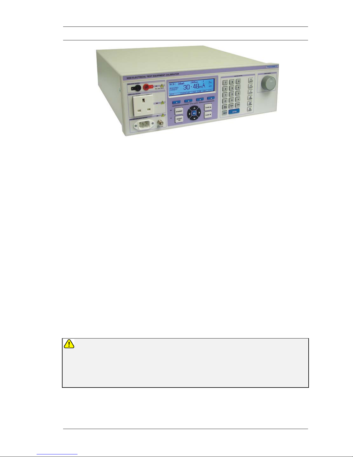
3200B Electrical Test Equipment Calibrator Introduction
The 3200 Electrical Test Equipment Calibrator is a breakthrough in electrical test
equipment calibration providing a complete solution for testing:
Insulation Testers
RCD Testers
LOOP Testers
Portable Appliance Testers (PATs)
Extended Functionality
The 3200B Calibrator can be enhanced with options to provide high accuracy
resistance, increased resistance range (up to 10GΩ) for Insulation testers, auto loop
measurement and two external resistance inputs to extend the range of available
resistors.
A complete electrical test equipment calibration solution
Designed to provide an accurate cost effective portable instrument for the calibration
of Insulation & Continuity testers, RCD testers, LOOP testers, Multifunction testers
and Portable Appliance Testers (PAT), the 3200B calibrator can be combined with
the
ProCal Calibration System to allow automated calibration.
IMPORTANT OPERATIONAL NOTE
For correct operation the Phase (Live) and Phase (Neutral) MUST be connected round
the correct way (some plugs used in non-UK countries can be connected either way
round, therefore this check is necessary) For International models the 3200B
automatically detects incorrect polarity and will not power on until this is corrected
(function not required for UK models).

3200B SERIES OPERATION MANUAL
TRANSMILLE LTD. Page 7
Installation & Power Requirements for the 3200B
It is necessary that for correct operation the Phase (Live) and Phase (Neutral)
MUST be connected correctly (some plugs used in non-UK countries can be
connected either way round, therefore this check will be necessary). There should
only be a small voltage between Phase (Neutral) and Phase (Earth).
To keep the LOOP impedance value to a minimum, the mains input to the 3200B is
hardwired to the instrument. This avoids any introduction of unnecessary
impedance. It is desirable that the 3200B is connected to a supply point with low
LOOP impedance as this will limit the lowest value available LOOP impedance from
the 3200B using as good a quality outlet (contact wise) as possible.

3200B SERIES OPERATION MANUAL
TRANSMILLE LTD. Page 8
Designed for use in the laboratory or portable on-site calibration.
The 3200B calibrator is suitable for use in the standards laboratory. The fast warm
up time combined with the small case and low weight make the 3200B series
calibrator also ideal for onsite calibration. The serial interface allows direct
connection to a PC/laptop.
Retro fit options allow extra functions to be added.
Several internal retro fit options including increased resistance range (up to 10GΩ)
for Insulation testers, auto loop, high accuracy resistance and external resistance
input allow the user to select the most cost effective solution for the calibration work
with the ability to add extra functions at a later date.
USB Interface as standard.
All functions and outputs of the 3200 calibrator are fully programmable over the USB
interface. The use of the USB interface saves the cost of fitting GPIB cards to the
PC, and also allows easy connection to portable PC’s, reducing the set up time for
on-site calibration.
Input / Output Connection
The input and output terminal configuration has been designed to enable simple
connection to a full range of instrumentation. Use of a dedicated socket directly on
the front panel allows resistance measurement functions such as LOOP testing to
be calibrated to include residual values right up to the socket.
All outputs are isolated when not in use, with an LED indicator showing the active
input / output terminal(s).
3200B SERIES OPERATION MANUAL
TRANSMILLE LTD. Page 9
Preparing the calibrator for use.
Initial Inspection.
After shipment the calibrator should be inspected for any signs of external damage.
Should external damage be found contact the carrier immediately. Do not connect a
damaged instrument to the line power as this may result in internal damage. Please
retain the original packaging; this should be used when returning the calibrator for
service and recalibration.
Shipping Checklist
1 x USB interface lead
1 x Operation manual (this document)
1 x PAT Test Lead
1 x Adapter Connection Lead (only if option FLASH or BREAKD fitted)
Lifting and carrying the calibrator
The calibrator can be carried by one person supporting the underneath (note:
observe all normal practices for health and safety when carrying). A custom carry
case with shoulder strap is available if the calibrator is to be regularly transported see options list. The calibrator should always be placed down on a firm flat surface
on its base feet. Avoid knocking or banging the calibrator and always place down
smoothly.
Warning
DO NOT DROP THE CALIBRATOR – This may cause internal damage
3200B SERIES OPERATION MANUAL
TRANSMILLE LTD. Page 10
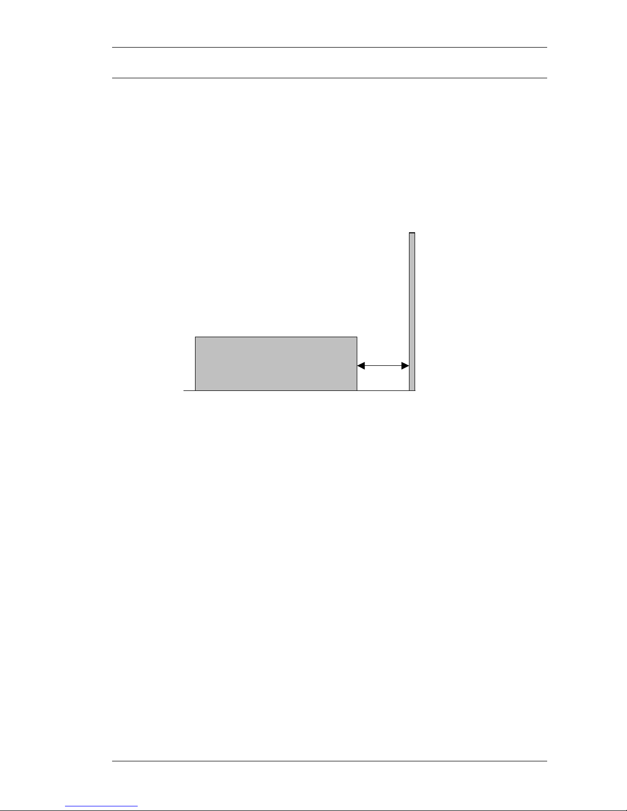
Positioning the Calibrator.
The calibrator can be used free standing on a bench or mounted in a standard 19”
rack enclosure. The calibrator can be operated at any angle; the two front feet have
tilt legs for bench operation.
A 2” (5cm) space behind the instrument is also required for line and interface
connections (See diagram):
Minimum 2” (5cm) Clearance
3200B SERIES OPERATION MANUAL
TRANSMILLE LTD. Page 11
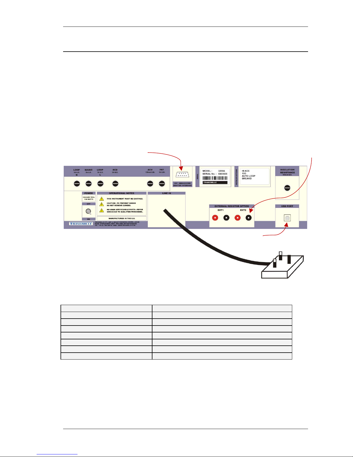
Rear Panel Connections and Controls
Connections on the rear panel consist of a 9 Pin Serial interface connector for the
computer interface; this is optically isolated from the calibrator outputs.
Fuse holders for individual instrument functions are accessible from the back of the
alibrator. These are bayonet type fuse holders which allow a screwdriver to be used
to turn the fuse carrier until it ‘pops’ out of the fuse holder body. The fuse carrier can
then be withdrawn from the fuse holder body for inspection / replacement.
Fuse Description Fuse Value
LOOP N (Neutral) 5A Anti Surge
MAINS 2A Anti Surge
LOOP L (Live) 5A Anti Surge
RCD 2A Quick Blow
ACV 100mA Quick Blow
PAT 100mA Quick Blow
INSULATION RESISTANCE 100mA Quick Blow
USB Port
Flash /
Breakdown Box
External Resistors (option)

3200B SERIES OPERATION MANUAL
TRANSMILLE LTD. Page 12
Setting and Checking the Line Voltage.
Warning
The line power cord must have an earth conductor to avoid the
risk of shock. This instrument must be correctly earthed.
The calibrator has been designed to work from either 100-120 Volt line supply or
200 - 240 Volt line supply. Check Supply voltage as marked on the rear panel before
connecting to power line. Connecting the calibrator to the wrong supply will cause
internal damage to the instrument. To change the line voltage it is necessary to
remove the instrument covers and rewire the transformer. The calibrator has been
shipped wired for 110V operation in the USA, 230V operation in the UK and Europe.
3200B SERIES OPERATION MANUAL
TRANSMILLE LTD. Page 13
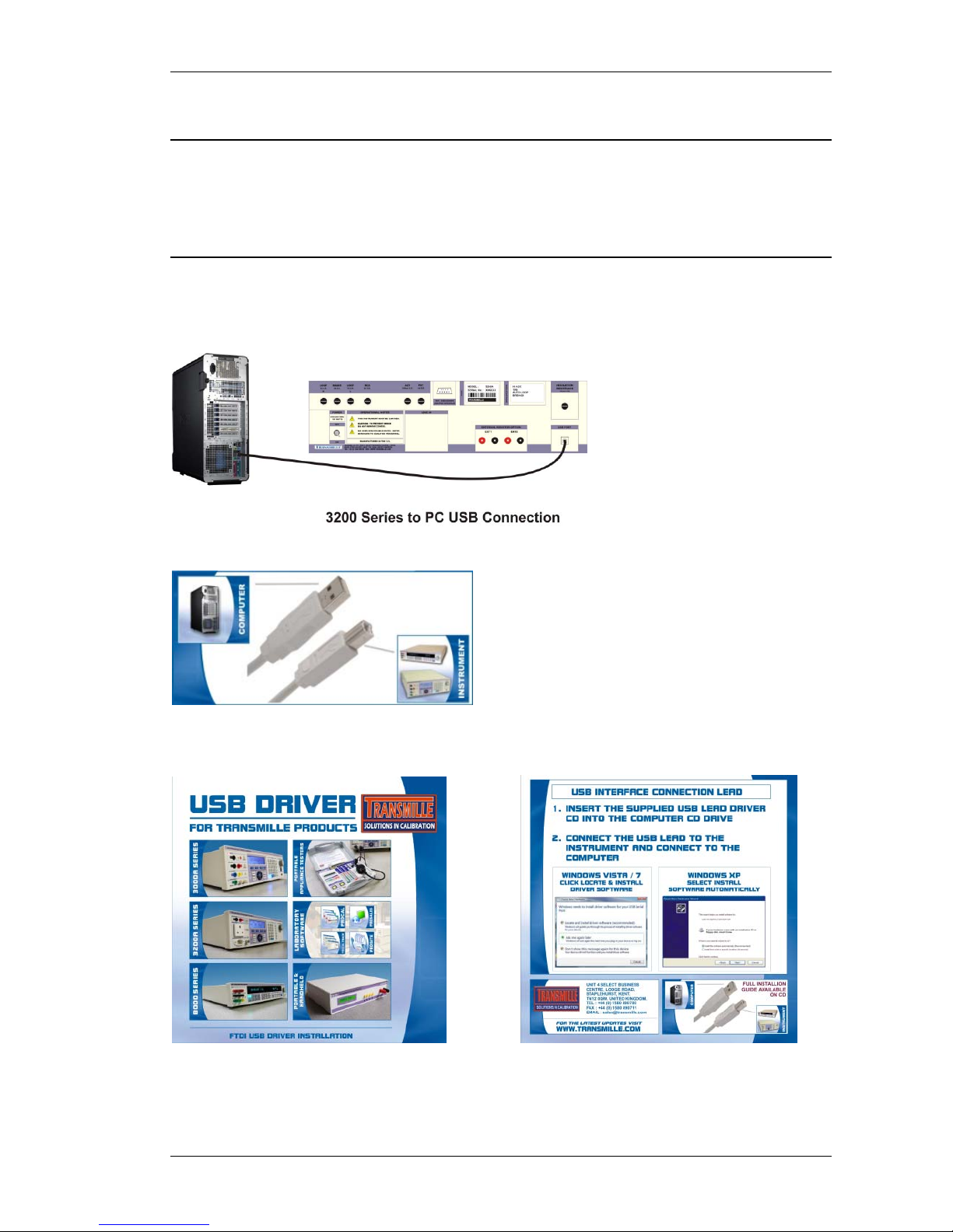
Connecting to a computer
A USB cable (supplied) should be used to connect the calibrator to a USB port
on the PC.
Connection Details
Connection from calibrator to PC :
Also supplied is a USB driver on CD :
For details on installing USB driver see appendix A.

3200B SERIES OPERATION MANUAL
TRANSMILLE LTD. Page 14
Powering up the calibrator
After connecting line power, the calibrator can be switched on with the line power
switch on the rear panel.
The front panel display will illuminate indicating power. The display will show
program version number and after a short delay, during which time the processor
performs a self-test of the instrument, the display will show the default start-up
display:
Press the ‘INFO’ soft key to display the firmware version, serial number and options
fitted to the 3200B.
3200B SERIES OPERATION MANUAL
TRANSMILLE LTD. Page 15
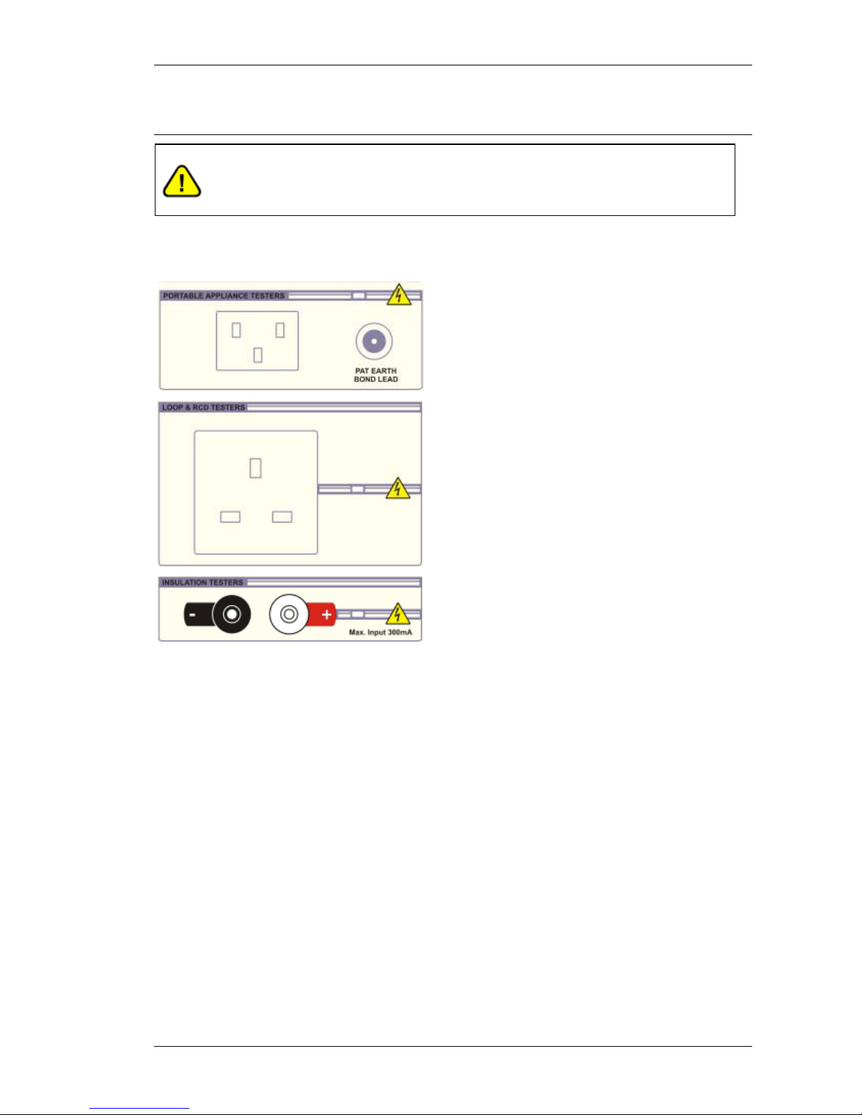
Output Connections
Warning - Risk of shock.
High voltages may be present on the output sockets.
Output sockets comprise of the following types:
IEC 3-Pin Socket:
For use with the supplied PAT test lead.
13A Socket (UK)*:
For use directly with LOOP /
RCD tester or EURO
Socket* or Australian
Socket*
* Fitted depending on country
4mm Safety Sockets: For connection to
Insulation and Continuity Testers
3200B SERIES OPERATION MANUAL
TRANSMILLE LTD. Page 16
Operation
SAFETY WARNINGS
This instrument is capable of generating high voltages
WARNING
The information in this section is intended only for qualified
personnel. The user must at all times be adequately protected
from electric shock. Qualified personnel must ensure that
operators of the equipment are adequately insulated from
connection points.
A carry-case is available for regular transportation of the calibrator.
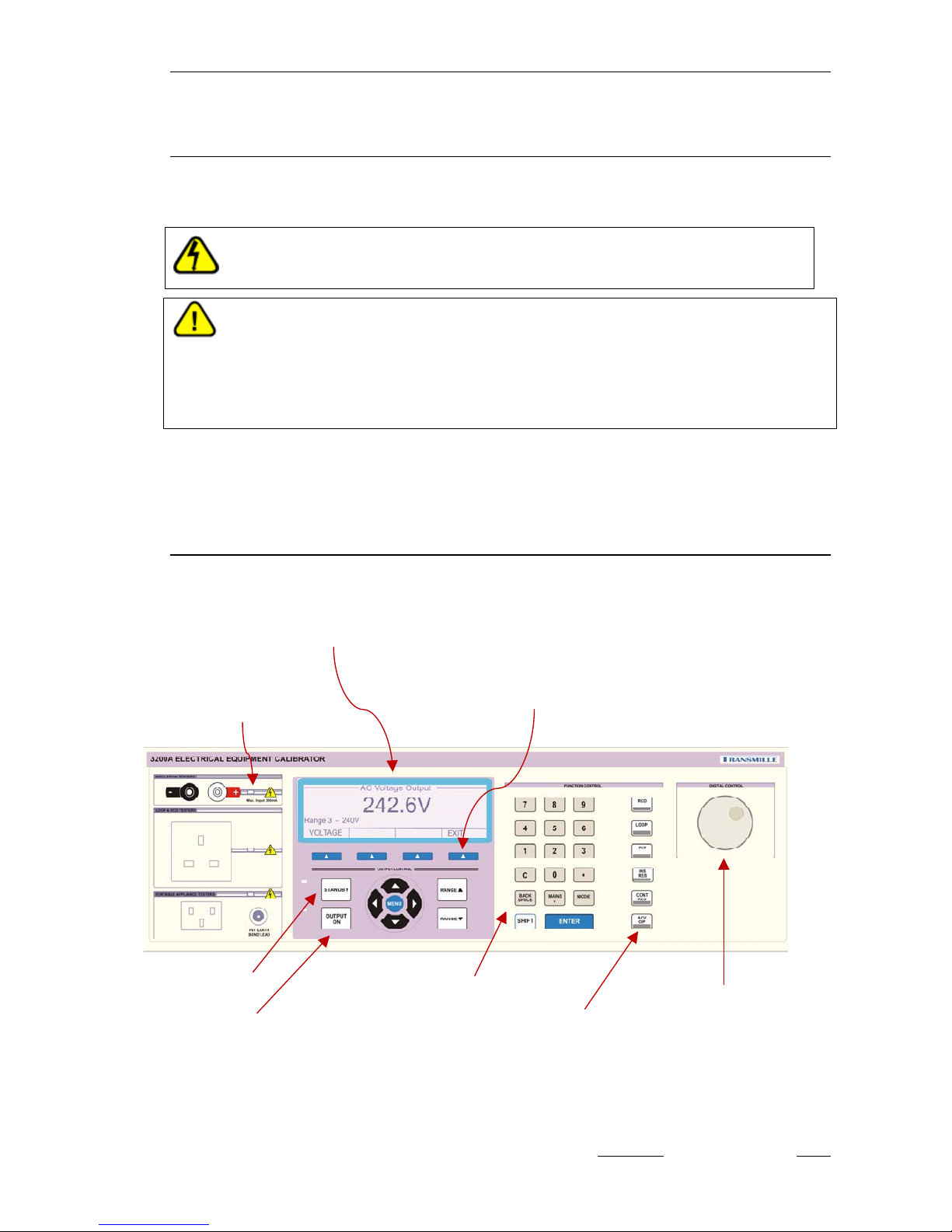
Introduction to Operation
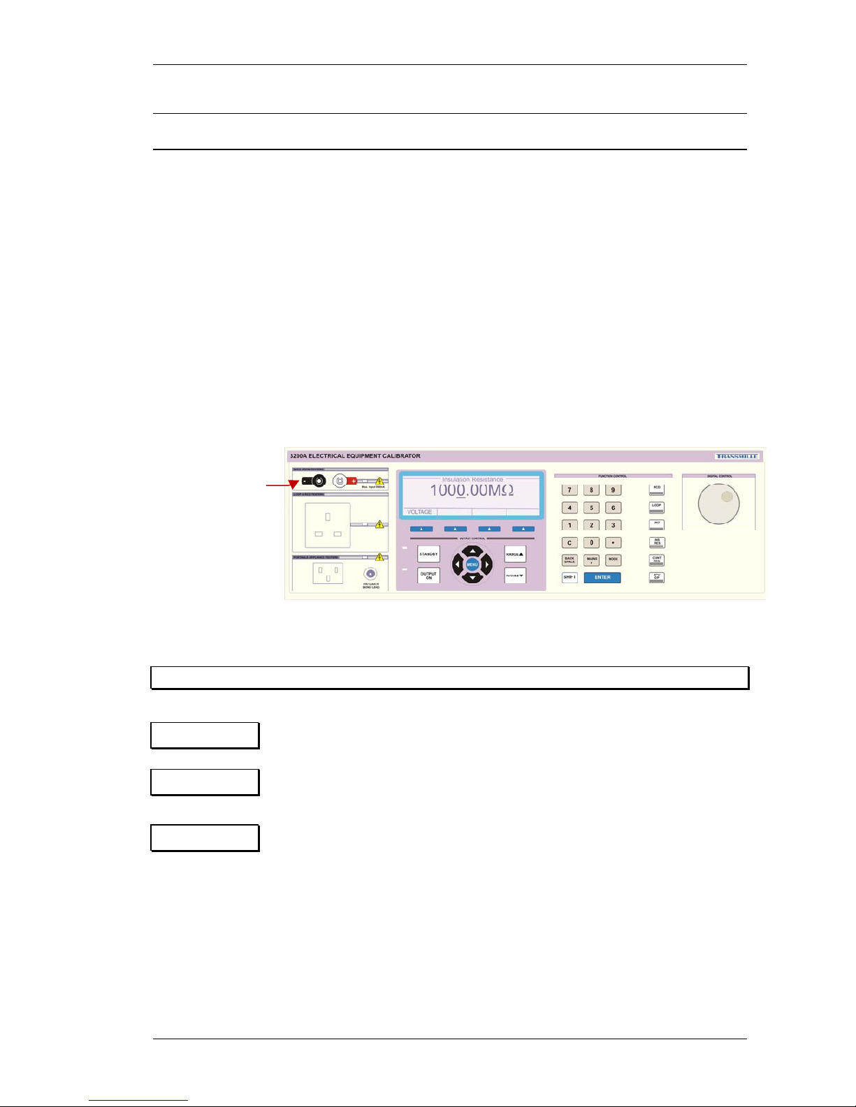
All functions of the 3200B Calibrator can be controlled from the front panel or
controlled remotely by a computer over the USB interface.
Active Terminal / LED indicator
LCD Display with
integral
Menu buttons (soft keys)
Standby button
Output On button
Numeric keypad
Function keys
Digital control
3200B SERIES OPERATION MANUAL
TRANSMILLE LTD. Page 17
Front Panel Keyboard
The front panel of the 3200B Calibrator utilises a high quality custom rubber
keyboard with tactile feel buttons and integral display window. The front panel is
therefore sealed against the ingress of moisture and dirt enabling the calibrator to be
used in most working environments without risk of early failure of the operating
buttons. The front panel can easily be wiped clean with a soft cloth. Care should be
taken not scratch the display window. All graphics are ‘under printed’ making them
rugged and durable.
IMPORTANT NOTE
The front panel key buttons are for use with fingers only - do not press
the key with hard or sharp objects e.g. Ball-point pens, pencils,
screwdrivers etc. Repeated actions like this will almost certainly cause
the keyboard to fail. (This will not be covered under warranty). Care
should also be taken when transporting the instrument, do not place
test leads or other objects on top of the panel which may come into
contact with the display area and cause damage.
3200B SERIES OPERATION MANUAL
TRANSMILLE LTD. Page 18
The Keyboard is divided into sections to allow rapid operation.
The Numeric section allowing values to be entered,
Functions keys for RCD, LOOP, PAT, Insulation Resistance, Continuity Resistance
and ACV Output
Range up and range down keys allows range changing for the currently selected
function
Left/right arrow keys select the digit to be controlled by the digital control knob.
Output on / Standby keys allow the calibrator output to be disconnected from the
terminals. Led indicators are incorporated in these switches to clearly show the
output status.
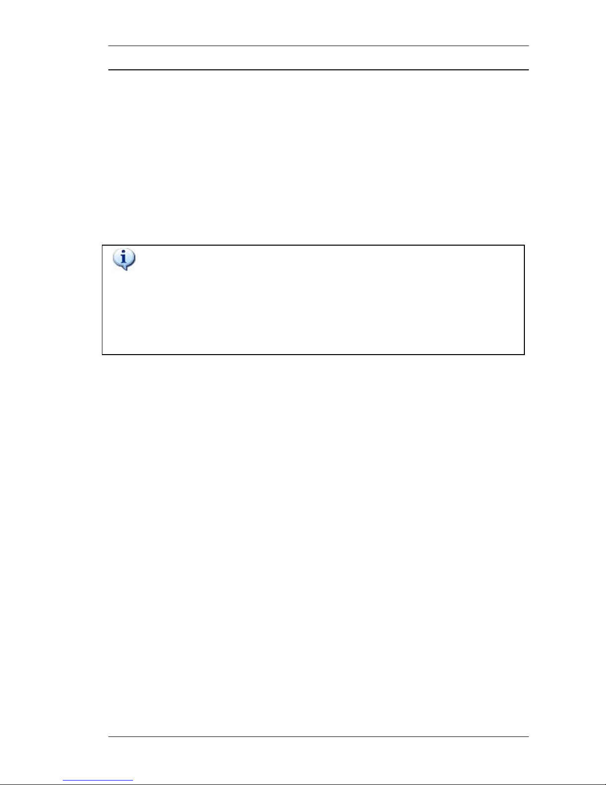
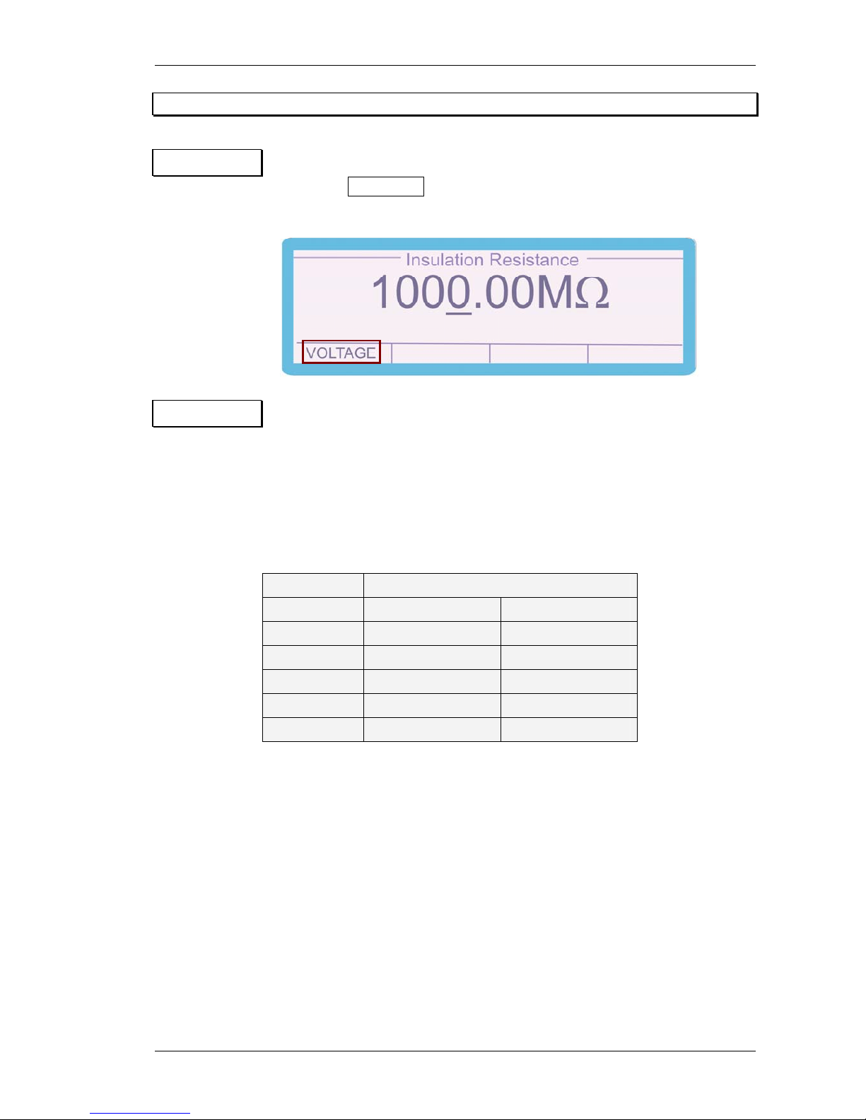
Graphic LCD Display
A back lit graphic LCD display shows the present setting and instrument status. The
bottom line of the display is used to assign the function of the four soft keys
immediately under the display. The displays back light automatically turns off if no
activity takes place. The back light turns on as soon as a key is pressed or a
command is received.
Soft keys
3200B SERIES OPERATION MANUAL
TRANSMILLE LTD. Page 19
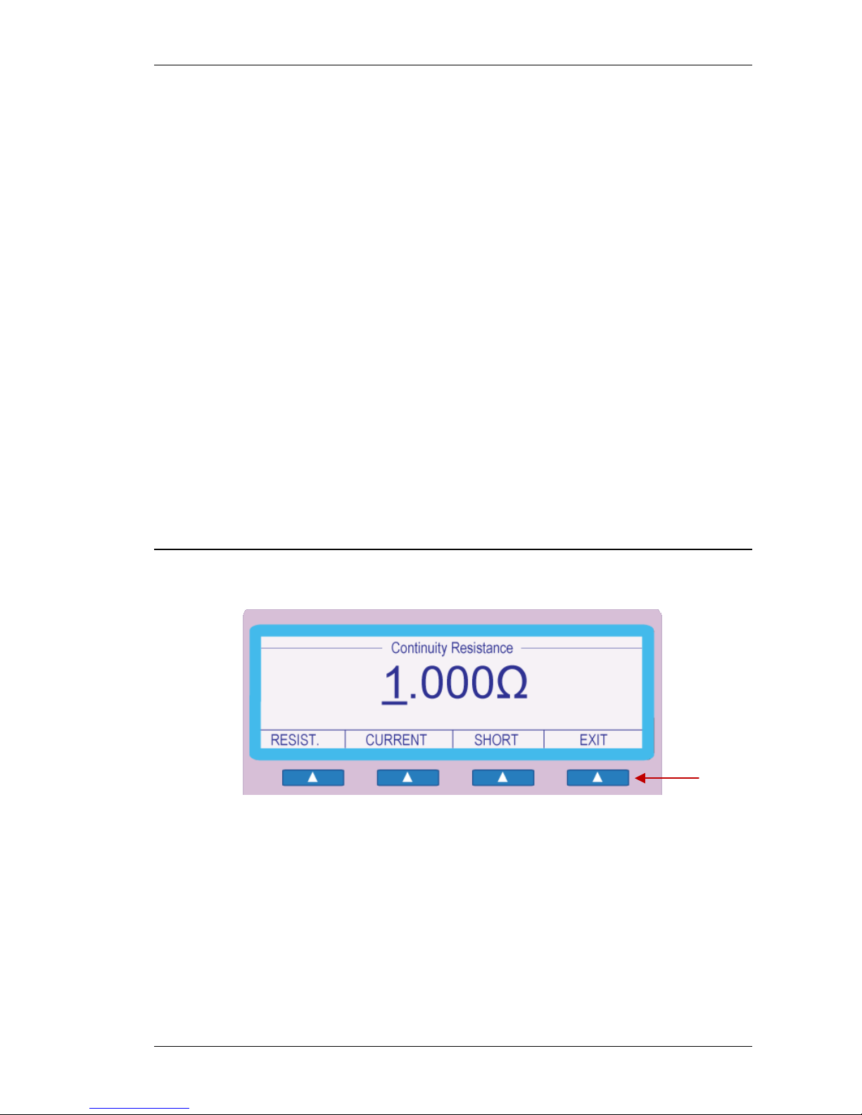
Using the Digital Control
A digital potentiometer allows the ‘highlighted digit’ on the display to be incremented
(turning clockwise) or decrement (turning anti-clockwise).
Clockwise Rotation
(Increment Digit)
Anti-Clockwise Rotation
(Decrement Digit)
Selected digit
marker.
Cursor Keys can be used to
move the position of the digit
marker, and increment /
decrement the digit.
3200B SERIES OPERATION MANUAL
TRANSMILLE LTD. Page 20
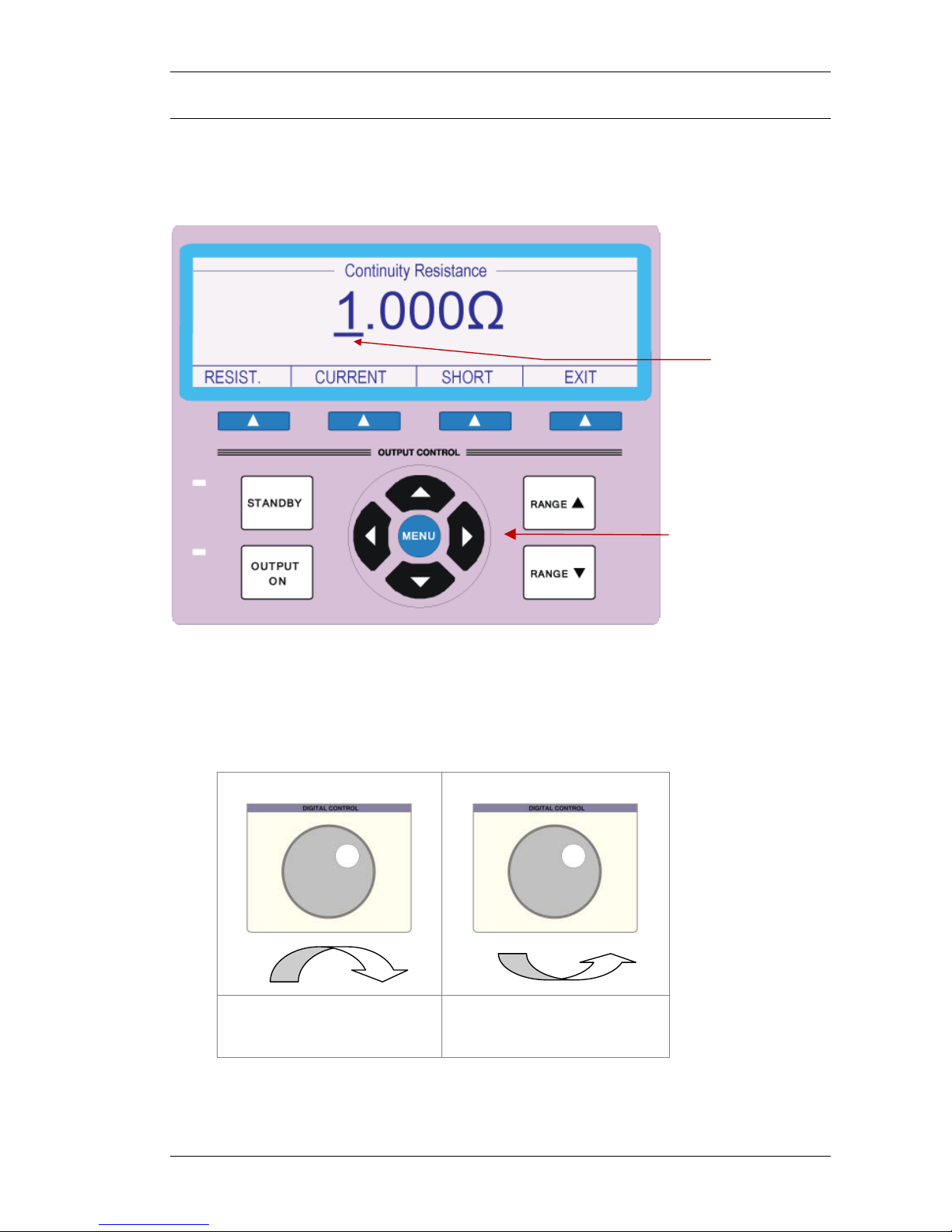
Terminal status LEDs
LED’s above the terminals indicate the active input / output.
PAT Test IEC Socket
WARNING
Dangerous voltage may be present on these terminals.
LOOP & RCD TEST Socket
WARNING
Dangerous voltage may be present on these terminals.
INSULATION TEST 4mm terminals
WARNING
Dangerous voltage may be present on these terminals.
PAT GND Terminal Post
Active terminals indicated by
illuminated LED
3200B SERIES OPERATION MANUAL
TRANSMILLE LTD. Page 21
Calibrating Instruments Using the 3200B
Calibrating Insulation Testers
The 3200B has six functions for calibrating insulation and continuity testers:
1. Resistance output for insulation testing (0MΩ to 2GΩ, option to 10GΩ)
2. Measurement of insulation test voltage; ranges 50V, 100V, 250V, 500V & 1000V
3. Measurement of insulation test current (16th and 17th edition standards)
4. Resistance output for continuity testing (0.2Ω - 20.0Ω Variable, 100Ω & 1kΩ)
5. Measurement of continuity current (@ 1Ω)
6. A.C. voltage output at 100V, 200V, 240V, 300V and 400V
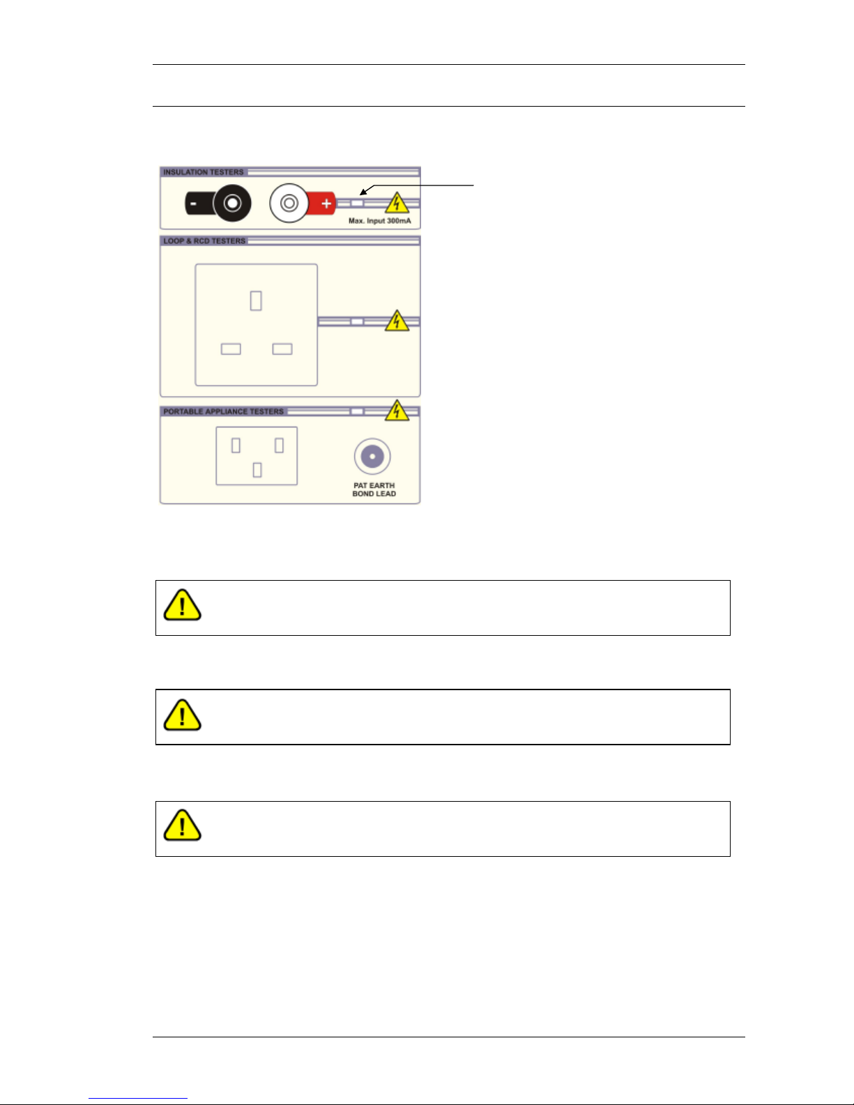
1. High Value Resistance for Insulation Testing
Step 1 Select ‘INS RES’ from the function key section of the 3200 front panel
Step 2 Connect the insulation tester to the Black & Red 4mm terminals.
Step 3 Enter the required resistance in MΩ from 10kΩ to 10,000MΩ
on the keyboard followed by Enter. An alternative way to
select the required resistance is to use the digital Control to
increment / decrement the digit indicated by the cursor. The
Left and Right arrow keys allow the selected digit to be
changed
Use the 4mm sockets labelled
INSULATION TESTERS for all insulation
meter tests.
3200B SERIES OPERATION MANUAL
TRANSMILLE LTD. Page 22
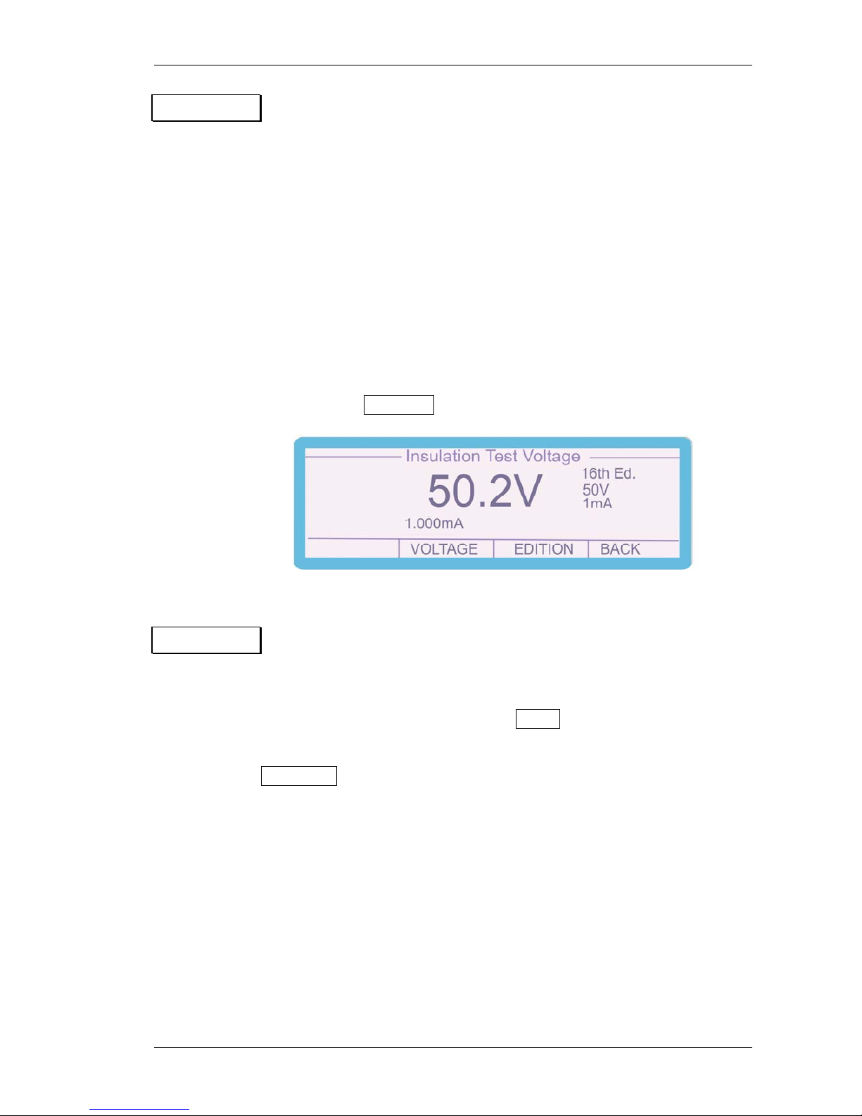
2. Measuring Insulation Test Voltages & Current
Step 1 From the Insulation Resistance menu displayed on the 3200B,
select the VOLTAGE function using the soft key.
Step 2 Select the required voltage range using either the digital Control or the
up / down arrow keys. Ranges include 50V, 100V, 250V, 500V and 1000V.
The impedance of each range is automatically set to give the correct
load 1mA / 0.5mA (see test current below) at the applied nominal
voltage range.
RANGE INPUT IMPEDANCE
1mA 0.5mA
50V 50 kOhm 100 kOhm
100V 100 kOhm 200 kOhm
250V 250 kOhm 500 kOhm
500V 500 kOhm 1 MOhm
1000V 1 MOhm 2 MOhm
3200B SERIES OPERATION MANUAL
TRANSMILLE LTD. Page 23
Step 3 Select the required measurement current using the Soft Keys.
The default setting for current load is 0.5mA nominal which is the
correct load/test current for the 17th Edition equipment -
e.g. must be able to supply 0.5mA at the specified test voltage.
Older insulation testers (16th Edition) produced 1mA current
at the specified test voltage. The 3200B should be set to 1mA
current for these instruments. Very old testers may only produce
a very small current and the voltage will collapse under any load
– these should be tested using additional equipment.
The instruments input impedance setting can be change by
pressing the EDITION soft key.
Step 4 Press the test button on the insulation tester to apply the insulation
test voltage and read the voltage and current on the 3200B
display. To return from the Voltage measurement screen to
the insulation resistance select the BACK menu item using the
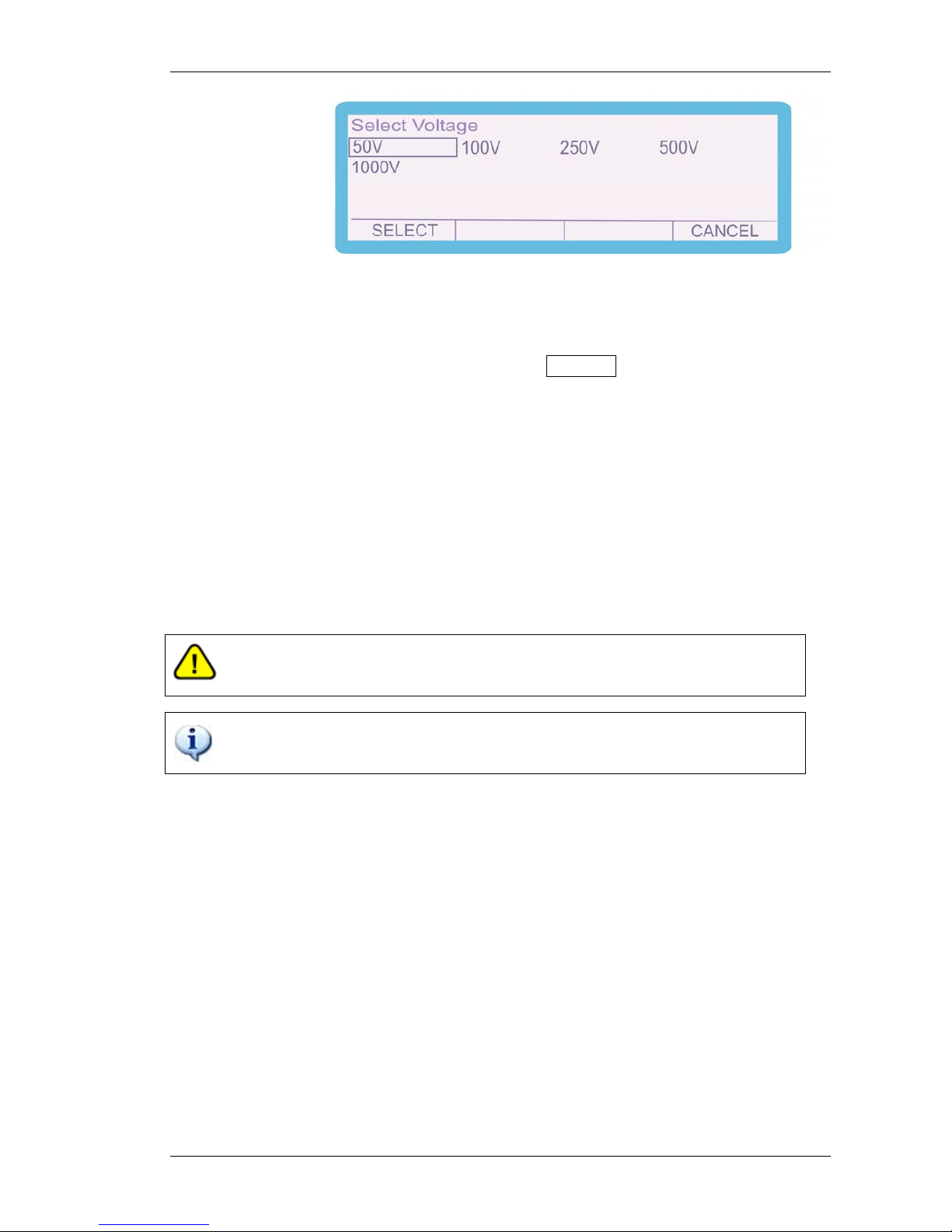
soft key. To change the voltage range on the 3200B press the
VOLTAGE soft key and select the required voltage as shown:
3200B SERIES OPERATION MANUAL
TRANSMILLE LTD. Page 24
Highlight the required voltage by using the curser keys and or the
digital control and then press the SELECT soft key.
If the voltage applied by the tester is less than 30%
of the range or the polarity is incorrect, the display will show
0V (note some tester’s ‘positive’ red terminals are supplying
negative voltage and need to have test leads reversed).
NOTE:- NEGATIVE INPUT OF 3200B (BLACK) IS
CONNECTED TO SUPPLY EARTH.
Warning : The maximum input voltage is 1100 volts
The correct polarity must be applied to obtain a reading
 Loading...