

DECLARATION OF CONFORMITY
Manufacturer's Name: Transmille Ltd.
Manufacturer's Address: Unit 4, Select Business Centre
Lodge Road
Staplehurst
TN12 0QW.
United Kingdom.
Declares, that the product
Product Name: Multi-product Calibrator
Model Number: 3050A / 3041A / 3010A
Product Options:
This declaration covers all options of the above product(s)
Conforms with the following European Directives:
The product herewith complies with the requirements of the
Low Voltage Directive 73/73EEC and the EMC Directive
89/336/EEC (including 93/68/EEC) and carries the CE
Marking accordingly
Conforms with the following product standards:
EMC
IEC616326-1:1997+A1:1998 / EN 61326-1:1997+A1:1998 EN55011:1991
Standard Limit
IEC 61000-4-2:1995+A1:1998 / EN 61000-4-2:1995 Group 1Class A
IEC 61000-4-3:1995 / EN 61000-4-3:1995 4kV CD, 8kV AD
IEC 61000-4-4:1995 / EN 61000-4-4:1995 3 V/m, 80-1000 MHz
IEC 61000-4-5:1995 / EN 61000-4-5:1995 0.5kV signal lines, 1kV power lines
IEC 61000-4-6:1996 / EN 61000-4-6:1996 0.5kV line-line, 1kV line-ground
IEC 61000-4-11:1994 / EN 61000-4-11:1994 3V, 0.15-80 MHz I cycle, 100%
Dips: 30% 10ms; 60% 100ms
Interrupt > 95%@5000ms
SAFETY
IEC 61010-1:1990+A1:1992+A2:1995 / EN 61010-1:1993+A2:1995
16/01/2011
Date Of Issue Managing Director
Revision No: 1.00 : 16/01/2011
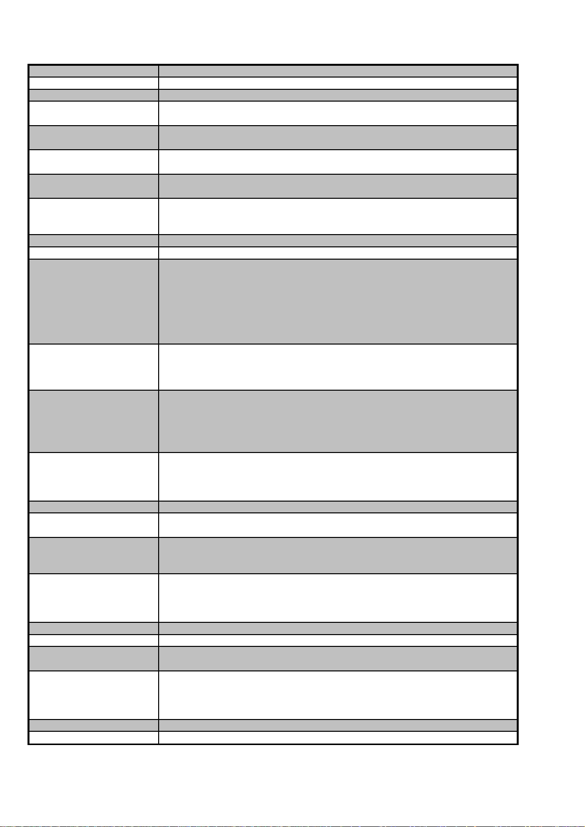
3050A EXTENDED SPECIFICATIONS General Specifications TRANSMILLE LTD
y
r
Warm Up Time
Double the time since last used up to 20 minutes maximum
Standard Interfaces RS232
Optional Interfaces GPIB (IEEE-488) : USB (Universal Serial Bus)
Temperature Performance Storage : -5°C to +60°C
Operation : 0°C to +50°C
Relative Humidity Operation : <80% to 30°C, <70% to 40°C, <40% to 50°C
Storage : <95%, non-condensing
Altitude Operation : 3000m (10,000ft) Maximum
Transit : 12000m (40,000ft) Maximum
EMC & Safety The calibrator line input plug must be earthed
See D.O.C for full details
Line Power Line Voltage Selectable : 110V / 230V
Line Frequency : 50Hz to 60Hz
Line Voltage Variation : -6% +10%
Power Consumption 28 Watts (Standby) 200 Watts (Maximum)
Low Analogue Isolation 100V
Connections
Voltage / 2 Wire Resistance 1x Black : 1x Red 4mm Safety sockets
Low Current (<=2A)
High current (>2A)
Earth Connection
1x Black : 1x Red 4mm Safety sockets
1x Blue : 1x Yellow 4mm Safety sockets
1x Green 4mm Safety Socket
Oscilloscope Functions 2x BNC terminal
Adapter Interface 1x Female 'D' type socket
RS232 Interface 1x Female 'D' type socket
RS232 Settings Baud Rate 9600
Parit
None
Data Bits 8
Stop Bits 1
Display Information Type Backlit blue on white STN Type
Viewing Area 133mm * 39mm
Resolution 240 x 64 dots
Backlight Type LED
Brightness
230 to 260 cd/m
2
Indicators Voltage / Current / High Current Red LED (between terminals)
Negative to ground Green LED (left of Earth terminal)
Oscilloscope Green LED (right of BNC Connector)
Feature Connector (Ext. Pod) Green LED (right of 'D' type connector)
Keyboard Ergonomic Rubber Keyboard
Fuses Mains Inlet 3.15A A/S (240 Volt)
5A A/S (110 Volt operation)
Isolation Outputs are opto-isolated from mains earth and the RS-232 interface
Maximum common mode voltage between earth and the
low terminals 30 Volts ac/dc.
Dimensions & Weights
Calibrator Only 14cm x 43cm x 46cm : 12.5kgs
Calibrator in Shipping Box 58cm x 56cm x 37cm : 15kgs
Calibrator in Soft Carry Case 49cm x 50cm x 19cm : 13.5kgs
Calibrator in Hard Transit case 55cm x 56cm x 26cm : 22kgs
Warranty Period 3 Years (Parts & Labour)
Recommended Service Interval
Supplied Connections
1 Year
1x Serial Interface Connection
1x Mains Lead
1x Adaptor Connection Lead (if at least one adaptor ordered)
Optional Lead Set Kit 1x Voltage connection leadset
1x Low Current connection leadset
1x High current connection leadset
1x AC connection leadset
Mounting Kit (optional) 3U rack mount kit
Case Colou
Cream (RAL 9002)
Due to continuous development specifications may be subject to change.
3050A Extended Specifications
General Specifications : V1.50
Page 1
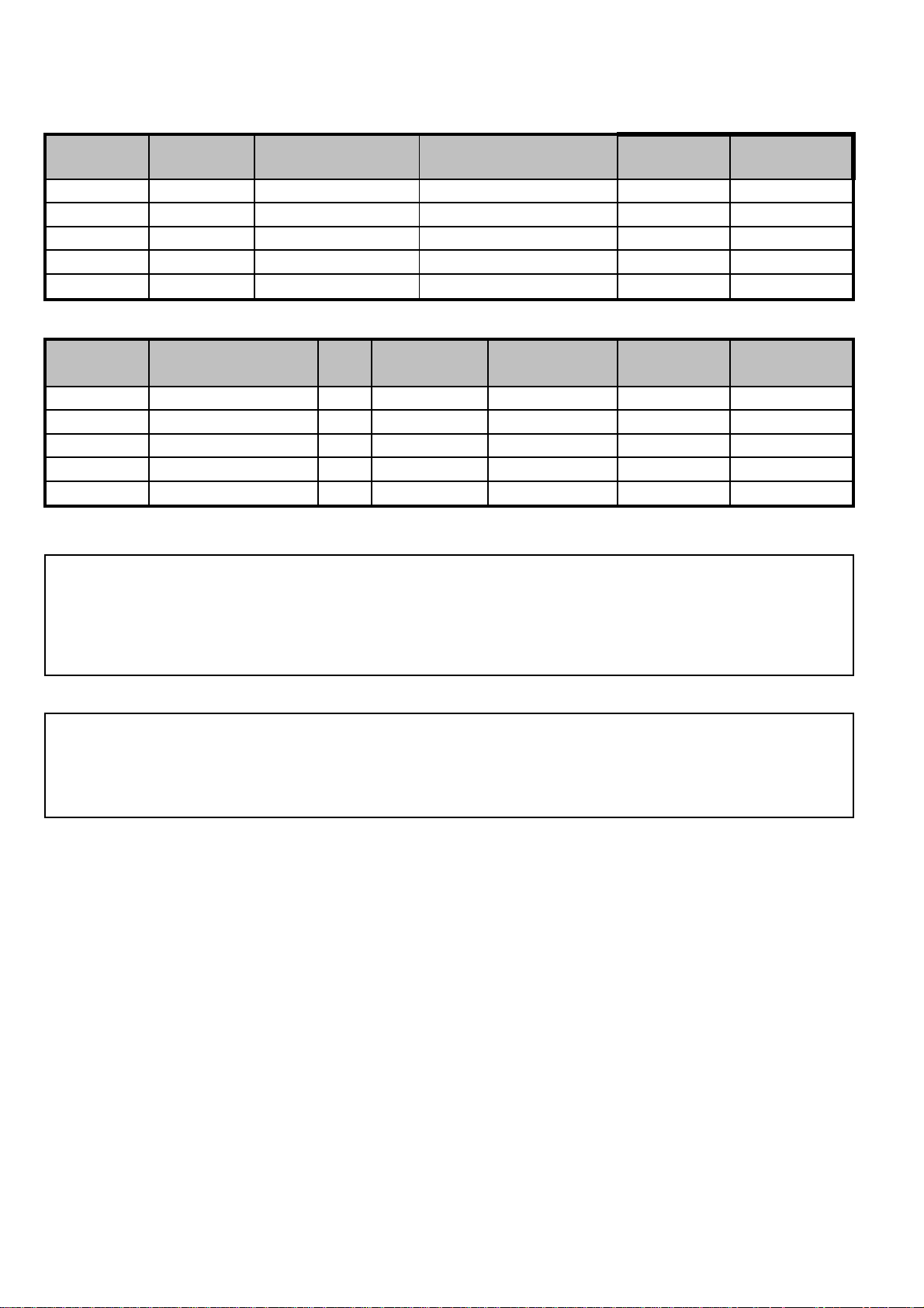
3050A EXTENDED SPECIFICATIONS DCV Specifications TRANSMILLE LTD
Note 1
All
Note 2: Limited by 50 Oh
Note 3
1 Year Total Accuracy Specifications at TCal ±5°C & Range Parameters
Range 1 Year Total
0-202mV 0.1uV
0.2-2.02V 1uV 50mA 150V 50 + 35
2-20.2V 10uV 50mA 150V 50 + 300
20-202V 100uV
200-1025V 1mV
Resolution
Max. Burden
Current
2
1mA
3
20mA
3
20mA
Typical Output
Resistance
1
50 Ohms
0.2 Ohms
0.2 Ohms
0.5 Ohms
0.7 Ohms
Overload
Protection
ppm set
20 V 50 + 4
1200V 50 + 3000
1200V 50 + 20000
Stability (Accuracy relative to calibration Standards)
4
Range
24 Hour Stability
ppm Set uV uV uV ppm Set uV uV uV
0-202mV 11.5 + 4 1.3 36.8 + 4 41.4 + 4 46 + 4 64.4 + 5.6
0.2-2.02V 11.5 + 12 4 36.8 + 35 41.4 + 35 46 + 35 64.4 + 49
2-20.2V 11.5 + 60 20 36.8 + 300 41.4 + 300 46 + 300 64.4 + 420
20-202V 11.5 + 1200 396 36.8 + 3000 41.4 + 3000 46 + 3000 64.4 + 4200
200-1020V 11.5 + 10000 3300 36.8 + 20000 41.4 + 20000 46 + 20000 64.4 + 28000
Noise
90 day Rel 180 Day Rel 1 year Rel 2 year Rel
ppm Set ppm Setppm Set
uV
Notes
:
owance must be made for output resistance when driving into a load.
m output impedance. - Low impedance output available
: Internally adjustable from 2mA to 30mA - Factory set to 20mA as standard.
For safety the trip is controlled by a fail-safe circuit independant of the processor which shuts the high voltage
output off in the event of an overload.
Note 4: Typical RMS noise figures at 50% of full scale, bandwidth 1Hz to 10Hz
High Voltage Safety
High voltage output is ramped to allow instrument under test to auto range.
Standby is automatically activated when setting voltages greater than 20V or 200V from a lower voltage.
Standby is automatically selected for high voltage (>20V) after 20 minutes on the same setting.
High voltage (> 20V) output is indicated to user through an audible warning beep.
An external high voltage output/standby control switch is available as an option.
2 Wire output / Remote sensing not available.
Isolation : Floating or grounded selection available as standard.
Maximum floating voltage : 100V
Specifications apply at TCal ± 5°C
Outside this range an allowance of 0.18 x 1 Year Spec. per °C should be added.
Due to continuous development specifications may be subject to change.
3050A Extended Specifications
DCV Specifications : V1.50
Page 2
3050A EXTENDED SPECIFICATIONS DCI Specifications TRANSMILLE LTD
A
2
1 Year Total Accuracy Specifications at TCal ±5°C & Range Parameters
Range Resolution Compliance Overload 1 Year Total
0-202uA 100pA 10mH 150V 0.0120 + 0.02
0.2-2.02mA 1nA 10mH 150V 0.0100 + 0.08
2-20.2mA 10nA 10mH 150V 0.0100 + 0.8
20-202mA 100nA 10mH 150V 0.0120 + 8
0.2-2.02A 1uA 10mH 150V 0.0500 + 90
2-22.0A 10uA 10mH 150V 0.0500 + 900
Max. Inductive
Load
Voltage Protection
4.2 Volts
4.2 Volts
4.2 Volts
4.2 Volts
4.2 Volts
3.9 Volts
% set u
Stability (Accuracy relative to calibration Standards)
1
Range
0-202uA 180pA 0.0080 + 0.02 0.0090 + 0.02 0.0100 + 0.02 0.0140 + 0.028
0.2-2.02mA 500pA 0.0064 + 0.08 0.0072 + 0.08 0.0080 + 0.08 0.0112 + 0.112
2-20.2mA 4nA 0.0064 + 0.8 0.0072 + 0.8 0.0080 + 0.8 0.0112 + 1.12
20-202mA 40nA 0.0072 + 8 0.0081 + 8 0.0090 + 8 0.0126 + 11.2
0.2-2.02A 1uA 0.0336 + 90 0.0378 + 90 0.0420 + 90 0.0588 + 126
2-22.0A
Notes
Note 1 : Typical RMS noise figures at 50% of full scale.
Note 2 : Power & temperature sensor on 22A range - microprocessor monitors & protects from overheating.
Higher resistance loads allow a longer ON period. See graph 1 for details.
Note 3 : Specifications apply to loads of less than 10% of the maximum burden voltage.
Note 4: Zero or floor allowance.
Specifications apply at TCal ± 5°C
Outside this range an allowance of 0.18 x 1 Year Spec. per °C should be added.
Noise
0.1-1Hz %Set uA %Set uA %Set uA %Set uA
20uA 0.0280 + 900 0.0315 + 900 0.0350 + 900 0.0490 + 1260
90 day Rel 180 Day Rel 1 year Rel 2 year Rel
Due to continuous development specifications may be subject to change.
3050A Extended Specifications
DCI Specifications : V1.50
Page 3
3050A EXTENDED SPECIFICATIONS DCI Specifications TRANSMILLE LTD
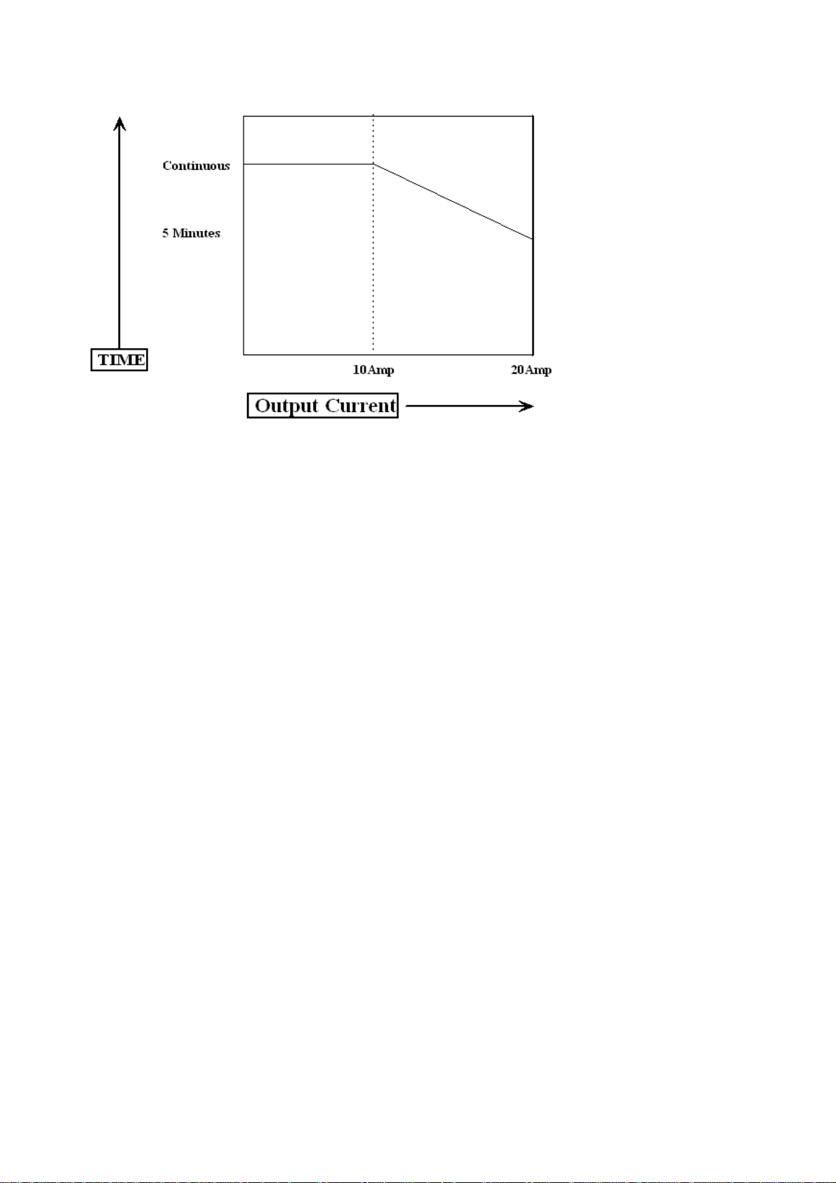
Graph 1* : Operating time on 22A range with current into a short circuit at 20°C
Continuous current availiable up to 10A output.
* Note Timing is started after a minimum period of 7 minutes at zero output.
Shorter periods will reduce the output time availiable.
Due to continuous development specifications may be subject to change.
3050A Extended Specifications
DCI Specifications : V1.50
Page 4

3050A EXTENDED SPECIFICATIONS ACV Specifications TRANSMILLE LTD
t
V
1
1
1mA
1
2
15mA
2
3
2
15mA
2
3
A
1 Year Total Accuracy Specifications at TCal ±5°C & Range Parameters
Range Frequency Resolution Typical Output
0-202mV 10 to 44Hz 1uV
45Hz to 1.999kHz 1uV
2 to 20KHz 1uV
0.2-2.02V 10 to 44Hz 10uV 50mA 0.2 Ohms 1200V 0.060 + 280
45Hz to 1.999kHz 10uV 50mA 0.2 Ohms 1200V 0.035 + 220
2 to 19.999KHz 10uV 50mA 0.2 Ohms 1200V 0.060 + 390
20 to 100kHz 10uV 50mA 0.2 Ohms 1200V 0.200 + 3000
2-20.2V 10 to 44Hz 100uV 50mA 0.2 Ohms 1200V 0.060 + 2.8mV
45Hz to 1.999kHz 100uV 50mA 0.2 Ohms 1200V 0.035 + 2.2mV
2 to 19.999KHz 100uV 50mA 0.2 Ohms 1200V 0.070 + 3.9mV
20 to 100kHz 100uV 50mA 0.2 Ohms 1200V 0.300 + 30mV
20-202V 40Hz to 1.999kHz 1mV
2 to 20KHz 1mV
200-1020V
40Hz to 1.999kHz 10mV
2 to 10KHz 10mV
Max. Burden
Current
1mA
1mA
20mA
20mA
Overload
Resistance % se
Protection
1 Year Accuracy
50 Ohms 20 V 0.070 + 45
50 Ohms 20 V 0.035 + 25
50 Ohms 20 V 0.100 + 190
0.5 Ohms 1200V 0.045 + 22mV
0.5 Ohms 1200V 0.090 + 39mV
0.7 Ohms 1200V 0.045 + 120mV
0.7 Ohms 1200V 0.090 + 290mV
Stability (Accuracy relative to calibration Standards)
Range Frequency 90 day Rel 180 Day Rel 1 year Rel 2 year Rel
0-202mV
10 to 44Hz 1Hz 0.0400 + 45 0.0450 + 45 0.0500 + 45 0.0700 + 63
45Hz to 1.999kHz 1Hz 0.0200 + 25 0.0225 + 25 0.0250 + 25 0.0350 + 35
2 to 20kHz 1Hz 0.0640 + 190 0.0720 + 190 0.0800 + 190 0.1120 + 266
0.2-2.02V
10 to 44Hz 1Hz 0.0400 + 280 0.0450 + 280 0.0500 + 280 0.0700 + 392
45Hz to 1.999kHz 1Hz 0.0200 + 220 0.0225 + 220 0.0250 + 220 0.0350 + 308
2 to 19.999kHz 1Hz 0.0360 + 390 0.0405 + 390 0.0450 + 390 0.0630 + 546
20 to 100kHz 1Hz 0.1360 + 3000 0.1530 + 3000 0.1700 + 3000 0.2380 + 4200
2-20.2V
10 to 44Hz 1Hz 0.0400 + 2.8mV 0.0450 + 2.8mV 0.0500 + 2.8mV 0.0700 + 4mV
45Hz to 1.999kHz 1Hz 0.0200 + 2.2mV 0.0225 + 2.2mV 0.0250 + 2.2mV 0.0350 + 3mV
2 to 19.999kHz 1Hz 0.0440 + 3.9mV 0.0495 + 3.9mV 0.0550 + 3.9mV 0.0770 + 5mV
20 to 100kHz 1Hz 0.2080 + 30mV 0.2340 + 30mV 0.2600 + 30mV 0.3640 + 42mV
20-202V
40Hz to 1.999kHz 1Hz 0.0264 + 22mV 0.0297 + 22mV 0.0330 + 22mV 0.0462 + 30mV
2 to 20kHz 1Hz 0.0560 + 39mV 0.0630 + 39mV 0.0700 + 39mV 0.0980 + 50mV
200-1020V
40Hz to 1.999kHz 1Hz 0.0240 + 120mV 0.0270 + 120mV 0.0300 + 120mV 0.0420 + 180mV
2 to 10kHz 1Hz 0.0560 + 290mV 0.0630 + 290mV 0.0700 + 290mV 0.0980 + 455mV
All specifications apply from 10% of full scale.
AC Frequency Accuracy = 30ppm of Setting
Frequency
Resolution
%Set uV %Set uV %Set uV %Set uV
5
u
Notes
Note 1: Current limited by 50 ohms output resistance.
Note 2 : Internally adjustable from 2mA to 30mA - Factory set to 20mA as standard
For safety the trip is controlled by a fail-safe circuit independant of the processor which shuts the high voltage
output off in the event of an overload.
Note 3 : Frequency and voltage combinations are limited. See Volt-Hertz profile in Graph 3
Note 4 : Allowance must be made for output resistance when driving into a load.
Note 5 : Zero or floor allowance.
Due to continuous development specifications may be subject to change.
3050A Extended Specifications
CV Specifications : V1.50
Page 5

3050A EXTENDED SPECIFICATIONS ACV Specifications TRANSMILLE LTD
y
s
.
A
2 Wire output / Remote sensing not available.
THD less than .6%
Isolation : Floating or grounded selection available as standard.
Specifications apply at TCal ± 5°C. Outside this range an allowance of 0.18 x 1 Year Spec. per °C should be added.
High Voltage Safet
High voltage output is ramped to allow instruments under test to auto-range.
Standby is automatically activated when setting voltages greater than 20V or 200V from a lower voltage
Standby is automatically selected for high voltage (>20V) after 20 minutes on the same setting for frequencie
up to 5kHz or 3 mins for frequencies above 5kHz. See graph 4
High voltage (> 20V) output is indicated to user through an audible warning beep
An external high voltage output/standby control switch is available as an option
Graph 3 : Volt-Hertz profile for 1000V AC range
Graph 4 : Time-Hertz profile for voltages above 20V
Due to continuous development specifications may be subject to change.
3050A Extended Specifications
CV Specifications : V1.50
Page 6

3050A EXTENDED SPECIFICATIONS ACI Specifications TRANSMILLE LTD
A
y
y
A
1 Year Total Accuracy Specifications at TCal ±5°C & Range Parameters
Range Frequency Resolution
20-202uA 10 to 44Hz + 0.4
45Hz to 1.999kHz 1nA 3 Volts 150V + 0.3
2kHz to 10Khz + 0.5
0.2-2.02mA 10 to 44Hz + 0.6
45Hz to 1.999kHz 10nA 3 Volts 150V + 0.4
2kHz to 10kHz + 0.7
2-20.2mA 10 to 44Hz +4
45Hz to 1.999kHz 100nA 3 Volts 150V + 3
2kHz to 10kHz +6
20-202mA 10 to 44Hz +40
45Hz to 1.999kHz 1uA 3 Volts 150V + 30
2kHz to 10kHz +60
0.2-2.02A 10 to 44Hz 10uA 3 Volts 150V + 450
45Hz to 2kHz + 400
2-22.0 A 10 to 44Hz + 9000
45Hz to 200Hz 100uA 2.8 Volts 150V + 6000
200Hz to 1kHz + 8000
All specifications apply from 10% of full scale.
Settling Time: For 50% change in output: Less than 3 second from standby to within specifications
Inductive Loads: Up to 1H may be connected without additional protection providing the
frequency / inductance combination does not exceed the maximum burden voltage.
Maximum Burden
Voltage (Peak)
Overload
Protection
1 year Accuracy
%Set
0.090
0.070
0.100
0.090
0.070
0.100
0.090
0.070
0.100
0.090
0.070
0.100
0.100
0.090
0.200
0.150
0.200
u
Stability (Accuracy relative to calibration Standards)
Range Frequenc
20-202uA 10 to 44Hz 1Hz 0.0560 + 0.4 0.0630 + 0.4 0.0700 + 0.4 0.0980 + 0.56
45Hz to 1.999kHz 1Hz 0.0360 + 0.3 0.0405 + 0.3 0.0450 + 0.3 0.0630 + 0.42
2kHz to 10kHz 1Hz 0.0640 + 0.5 0.0720 + 0.5 0.0800 + 0.5 0.1120 + 0.7
0.2-2.02mA 10 to 44Hz 1Hz 0.0560 + 0.6 0.0630 + 0.6 0.0700 + 0.6 0.0980 + 0.84
45Hz to 1.999kHz 1Hz 0.0360 + 0.4 0.0405 + 0.4 0.0450 + 0.4 0.0630 + 0.56
2kHz to 10kHz 1Hz 0.0640 + 0.7 0.0720 + 0.7 0.0800 + 0.7 0.1120 + 0.98
2mA-20.2mA 10 to 44Hz 1Hz 0.0560 + 4 0.0630 + 4 0.0700 + 4 0.0980 + 5.6
45Hz to 1.999kHz 1Hz 0.0360 + 3 0.0405 + 3 0.0450 + 3 0.0630 + 4.2
2kHz to 10kHz 1Hz 0.0640 + 6 0.0720 + 6 0.0800 + 6 0.1120 + 8.4
20-202mA 10 to 44Hz 1Hz 0.0560 + 40 0.0630 + 40 0.0700 + 40 0.0980 + 56
45Hz to 1.999kHz 1Hz 0.0400 + 30 0.0450 + 30 0.0500 + 30 0.0700 + 42
2kHz to 10kHz 1Hz 0.0640 + 60 0.0720 + 60 0.0800 + 60 0.1120 + 84
200-2.02A 10 to 44Hz 1Hz 0.0640 + 450 0.0720 + 450 0.0800 + 450 0.1120 + 630
45Hz to 2kHz 1Hz 0.0480 + 400 0.0540 + 400 0.0600 + 400 0.0840 + 560
2-22.0 A
Notes
Note 1 : Temperature sensor on 22A range - microprocessor monitors & protects from overheating.
Higher resistance loads allow a longer ON period. See graphs 5 and 6 for details.
Note 2 : Specifications apply to loads of less than 10% of the maximum burden voltage.
Specifications apply at TCal ± 5°C. Outside this range an allowance of 0.18 x 1 Year Spec. per °C should be added.
1
10 to 44Hz 1Hz 0.1360 + 9000 0.1530 + 9000 0.1700 + 9000 0.2380 + 12600
45Hz to 200Hz 1Hz 0.0960 + 6000 0.1080 + 6000 0.1200 + 6000 0.1680 + 8400
200Hz to 2kHz 1Hz 0.1360 + 8000 0.1530 + 8000 0.1700 + 8000 0.2380 + 11200
Frequenc
Resolution %Set uA %Set uA %Set uA %Set uA
90 day Rel 180 Day Rel 1 year Rel 2 year Rel
Due to continuous development specifications may be subject to change.
3050A Extended Specifications
CI Specifications : V1.50
Page 7

3050A EXTENDED SPECIFICATIONS ACI Specifications TRANSMILLE LTD
A
Notes
Note 1 : Temperature sensor on 22A range - microprocessor monitors & protects from overheating.
Higher resistance loads allow a longer ON period. See graph 5 for details.
Note 2 : Specifications apply to loads of less than 10% of the maximum burden voltage.
Driving Coils and Inductive Loads
When driving any load exceeding the maximum compliance voltage will cause the calibrator to trip into standby
The maximum compliance voltage on the 10Amp range is specified at a max 2.8V RMS, 7.8V Peak to Peak at 220V supply
Slightly higher compliances are available when powered from a 240V supply.
When using EA002 with leads supplied it is possible to drive 20Amps/50Hz from a 230V supply, falling to 10Amps at 400Hz
Specifications apply at TCal ± 5°C.
Outside this range an allowance of 0.18 x 1 Year Spec. per °C should be added.
Graph 5* : Operating time on 22A range with current into a short circuit at 20°C
Continuous current available up to 10A output.
* Note Timing is started after a minimum period of 7 minutes at zero output.
Shorter periods will reduce the output time availiable.
Due to continuous development specifications may be subject to change.
3050A Extended Specifications
CI Specifications : V1.50
Page 8

3050A EXTENDED SPECIFICATIONS Frequency Specifications TRANSMILLE LTD
y
)
Total Accuracy - Standard Accurac
Range 90 day 180 Day 1 year 2 year
ppm ppm ppm ppm
1Hz 16 18 20 28
10Hz 16 18 20 28
100Hz 16 18 20 28
1kHz 16 18 20 28
10kHz 16 18 20 28
100kHz 16 18 20 28
1MHz 16 18 20 28
10MHz 16 18 20 28
Total Accuracy - High Accuracy (Option
Range 90 day 180 Day 1 year 2 year
ppm ppm ppm ppm
1Hz 0.8 0.9 1 1.4
10Hz 0.8 0.9 1 1.4
100Hz 0.8 0.9 1 1.4
1kHz 0.8 0.9 1 1.4
10kHz 0.8 0.9 1 1.4
100kHz 0.8 0.9 1 1.4
1MHz 0.8 0.9 1 1.4
10MHz 0.8 0.9 1 1.4
Specifications apply at TCal ± 5°C.
Outside this range an allowance of 0.18 x 1 Year Spec. per °C should be added.
PWM (%) - Frequency Range 5Hz to 10kHz
5% to 95% Better than 0.001%
Due to continuous development specifications may be subject to change.
3050A Extended Specifications
Frequency Specifications : V1.50
Page 9

3050A EXTENDED SPECIFICATIONS DC Resistance Specifications TRANSMILLE LTD
Ω
Ω
Ω1Ω
Ω
Ω
Ω
Ω1kΩ
For the highest possible accuracy and dependability of the measured value, regardless of
the measurement technique used, the 3000 Series calibrators use passive standard resistors,
the calibrated value of which is displayed when selected.
1 Year Total Accuracy Specifications at TCal ±5°C & Range Parameters
Range Maximum
Current
0Ω
10Ω
100Ω
1kΩ
10kΩ
100kΩ
1MΩ
10MΩ
100MΩ
∗
∗
∗
0.5A - + 0.005
0.3A 0.060 + 0.005
0.1A 0.009 + 0.005
- 0.006 + 0.04
- 0.006 + 0.4
- 0.006 + 4
- 0.015 + 40
- 0.060 + 400
- 0.650 + 4000
Maximum
Voltage
-
-
10V
50V
100V
100V
100V
100V
Display
Resolution
10u
10u
100u
1m
10m
100m
10
1 Year Total Accuracy
% set Ohms
* 2-Wire only
Stability (Accuracy relative to calibration Standards)
Range 90 day Rel 180 Day Rel 1 year Rel
% Ohms % Ohms % Ohms % Ohms
0Ω
10Ω
100Ω
1κΩ
10κΩ
100κΩ
1ΜΩ
10ΜΩ
100ΜΩ
For 2-Wire connection allow 35mΩ on all resistance specifications.
The 2 and 4 Wire value for each resistor is calibrated. The 2-Wire value is measured at the terminals
The 4-Wire values are taken using the zero position to NULL the measuring system.
Specifications apply at TCal ± 5°C.
Outside this range an allowance of 0.18 x 1 Year Spec. per °C should be added.
- + 0.005 - + 0.005 - + 0.005 - + 0.005
0.0400 + 0.005 0.0450 + 0.005 0.0500 +
0.0064 + 0.005 0.0072 + 0.005 0.0080 +
0.0040 + 0.04 0.0045 + 0.04 0.0050 +
0.0040 + 0.4 0.0045 + 0.4 0.0050 +
0.0040 + 4 0.0045 + 4 0.0050 +
0.0080 + 40 0.0090 + 40 0.0100 +
0.0440 + 400 0.0495 + 400 0.0550 +
0.4000 + 4000 0.4500 + 4000 0.5000 +
0.005
0.005
0.04
0.4
4
40
400
4000
2 year Rel
0.0700 + 0.005
0.0112 + 0.005
0.0070 + 0.04
0.0070 + 0.4
0.0070 + 4
0.0140 + 40
0.0770 + 400
0.7000 + 4000
Due to continuous development specifications may be subject to change.
3050A Extended Specifications
DC Resistance Specifications : V1.50
Page 10

3050A EXTENDED SPECIFICATIONS Capacitance Specifications TRANSMILLE LTD
y
s
C
F
For the highest possible accuracy and dependability of the measured value, regardless of
the measurement technique used, the 3000 Series calibrators use passive standard capacitors,
the calibrated value of which is displayed when selected.
General Specifications
Range Maximum Display D
Voltage Resolution
10nF 50V 0.1pF 0.006 N/A
20nF 50V 0.1pF 0.006 N/A
50nF 50V 1pF 0.006 N/A
100nF 50V 10pF 0.006 N/A
1uF 30V 100pF 0.002 N/A
Specifications apply at 1kHz. Allow 20pF for lead effects.
No appreciable variation is noticable at frequencies below 1kHz.
R
s
Total Accurac
Range 90 day 180 Day 1 year 2 year
%% % %
10nF 0.32 0.36 0.4 0.56
20nF 0.32 0.36 0.4 0.56
50nF 0.32 0.36 0.4 0.56
100nF 0.32 0.36 0.4 0.56
1uF 0.48 0.54 0.6 0.84
Measurement method
Cp up to 1uF
above 1u
s
Capacitance is calibrated as value at the terminals
ie. displayed value incorporates capacitance of circuit up to and including the terminals
Specifications apply at TCal ± 5°C.
Outside this range an allowance of 0.18 x 1 Year Spec. per °C should be added.
Due to continuous development specifications may be subject to change.
3050A Extended Specifications
Capacitance Specifications : V1.50
Page 11

3050A EXTENDED SPECIFICATIONS DC Power Option Specifications TRANSMILLE LTD
A
V
General Specifications
Voltage Range 1V to 1000V DC
Current Range 0.3A to 20A DC
Output Terminals Voltage output from top (Black & White) terminals
300mA to 2A current output from middle 2A (Black & Red) terminals
2.01A to 20A current output from bottom 20A (Blue & Yellow) terminals
Note : Indicator LEDs for both sets of terminals will illuminate to indicate DC Power mode
1 Year Accuracy Relative to Calibration standards
Current Range Resolution Setting Zero
0.3A to 2A 200uA 0.08% 600uA
2.01A to 20
2mA 0.08% 6mA
1 Year Accuracy Relative to Calibration standards
oltage Range Resolution Setting Zero
20V 1uV 0.008% 500uV
200V 10uV 0.008% 5mV
1000V 100uV 0.008% 30mV
High Voltage Safety
High voltage output is ramped to allow instruments to auto range
Standby is automatically activated when setting voltages greater than 20V or 200V from a lower voltage
Standby is automatically selected for high voltage (>20V) after 20 minutes on the same setting
High voltage (> 20V) output is indicated to user through an audible warning beep
An external high voltage output/standby control switch is available as an option
22A available as standard - external amplifier not required
Specifications apply at TCal ± 5°C.
Outside this range an allowance of 0.18 x 1 Year Spec. per °C should be added.
Due to continuous development specifications may be subject to change.
3050A Extended Specifications
DC Power Option Specifications : V1.50
Page 12

3050A EXTENDED SPECIFICATIONS AC Power Option Specifications TRANSMILLE LTD
A
V
y
A
General Specifications
Voltage Range 1V to 1000V AC
Current Range 0.3A to 20A AC
Frequency Range 40 to 400Hz
Output Terminals Voltage output from top (Black & White) terminals
300mA to 2A current output from middle 2A (Black & Red) terminals
2.01A to 20A current output from bottom 20A (Blue & Yellow) terminals
Note : Indicator LEDs for both sets of terminals will illuminate to indicate AC Power mode
1 Year Accuracy Relative to Calibration standards
Current Range Resolution Setting Zero
0.2A to 2A 200uA 0.15% 800uA
2.01A to 20
2mA 0.25% 8mA
1 Year Accuracy Relative to Calibration standards
oltage Range Resolution Setting Zero
20V 1uV 0.05% 4.4mV
200V 10uV 0.06% 35mV
1000V 100uV 0.06% 150mV
Frequency range 45Hz to 400Hz
Power Factor = 1
Phase Specifications
Phase Angle Resolution Accurac
0° to 359.9° 0.1° 0.1° + 6us*
*6us represents 0.109° at 50Hz or 0.87° at 400Hz
Note : Phase accuracy specification applies for levels above 10V/.5A
3050 calibrators automatically correct for any errors in the phase caused by inductive
loading, for example when using the clamp coil adaptor.
High Voltage Safety
High voltage output is ramped to allow instruments to auto range
Standby is automatically activated when setting voltages greater than 20V or 200V from a lower voltage
Standby is automatically selected for high voltage (>20V) after 20 minutes on the same setting
High voltage (> 20V) output is indicated to user through an audible warning beep
An external high voltage output/standby control switch is available as an option
22A available as standard - external amplifier not required
Specifications apply at TCal ± 5°C.
Outside this range an allowance of 0.18 x 1 Year Spec. per °C should be added.
Due to continuous development specifications may be subject to change.
3050A Extended Specifications
C Power Option Specifications : V1.50
Page 13

3050A EXTENDED SPECIFICATIONS Oscilloscope Calibration Option TRANSMILLE LTD
Amplitude
Ranges 2mV/Div : 5mV/Div : 10mV/Div : 20mV/Div : 50mV/Div : 100mV/Div
200mV/Div : 500mV/Div : 1V/Div : 2V/Div : 5V/Div : 10V/Div : 20V/Div : 50V/Div
Sequence 1, 2, 5
Waveshapes Square Wave (positive going from ground) : DC
Frequency 1kHz
Frequency Accuracy 30ppm
Graticule Height 6 Graticules
Rise Time 2us
Fall Time 2us
Output Terminal Front BNC (Green LED indicates terminal active)
Range 90 Day Rel. 180 Day Rel. 1 Year Rel. 2 Year Rel.
@ 1MOhm load % uV % uV % uV % uV
2mV to 50V/Div 0.009 ± 20 0.01 ± 20 0.01 ± 5 0.014 ± 20
High Voltage Safety
High voltage output is ramped to allow instruments to auto range
Auto standby is activated when passing through 20V or 200V output values
High voltage (> 20V) output is indicated to user through an audible warning beep
An external high voltage output/standby control switch is available as an option
Amplitude Deviation
Deviation Range ±10%
Deviation Resolution Better than 10ppm
Range 90 Day Rel. 180 Day Rel. 1 Year Rel. 2 Year Rel.
% uV % uV % uV % uV
-10% to +10% 0.008 ± 20 0.01 ± 20 0.01 ± 20 0.014 ± 20
Timebase
Ranges 2ns/Div : 5ns/Div : 10ns/Div : 20ns/Div : 50ns/Div : 100ns/Div : 200ns/Div
500ns/Div : 1ms/Div : 2ms/Div : 5ms/Div : 10ms/Div : 20ms/Div : 50ms/Div
100ms/Div : 200ms/Div : 500ms/Div : 1s/Div : 2s/Div : 5s/Div
Sequence 1, 2, 5
Waveshape Comb below 100ns
Sine Wave above 100ns
Oscillator Internal Crystal TCXO
Output Terminal Front BNC (Green LED indicates terminal active)
Range 90 Day Rel. 180 Day Rel. 1 Year Rel. 2 Year Rel.
ppm ppm ppm ppm
2ns/Div to 5s/Div 4.5 4.75 5 6
Timebase Deviation
Deviation Range ±10% in 0.05% Steps
Deviation Resolution Better than 0.05%
Range 90 Day Rel. 180 Day Rel. 1 Year Rel. 2 Year Rel.
%%% %
-9.5% to +9.5%
0.01 0.01 0.01 0.01
Due to continuous development specifications may be subject to change.
3050A Extended Specifications
Oscilloscope Calibration Option : V1.50
Page 14

3050A EXTENDED SPECIFICATIONS Oscilloscope Calibration Option TRANSMILLE LTD
Levelled Sweep
Sweep Range
Waveform Sine Wave
Levelled Sweep 600mV pk-pk into 50 Ohms
Reference Level 50kHz
Output Terminal Front BNC (Green LED indicates terminal active)
Range 90 Day Rel. 180 Day Rel. 1 Year Rel. 2 Year Rel.
5MHz to 250MHz
Levelled Sweep
Frequency Accuracy See Time markers
50kHz Reference
Accuracy 90 Day Rel. 180 Day Rel. 1 Year Rel. 2 Year Rel.
Frequency Accuracy 27 ppm 29 ppm 30 ppm 36 ppm
Level Accuracy 0.4 % 0.45 % 0.5 % 0.7 %
Fast Rise Output
Rise/Fall Time Typically 1ns
5MHz to 250MHz
db db db db
0.8 0.90 1 1.4
Specifications apply at TCal ± 5°C.
Outside this range an allowance of 0.18 x 1 Year Spec. per °C should be added.
Due to continuous development specifications may be subject to change.
3050A Extended Specifications
Oscilloscope Calibration Option : V1.50
Page 15
 Loading...