

Testing 16th Edition Instruments
Testing the Insulation resistance function
The insulation measurement function of a tester measures high value resistance using a high voltage.
A high voltage is used to test that the insulation does not break down, and is an essential requirement
to this type of test.
To check the insulation measurement function of a tester it is nessarry to check both the applied test
voltage and also the accuracy of the resistance measurement.
Checking for the correct applied test voltage
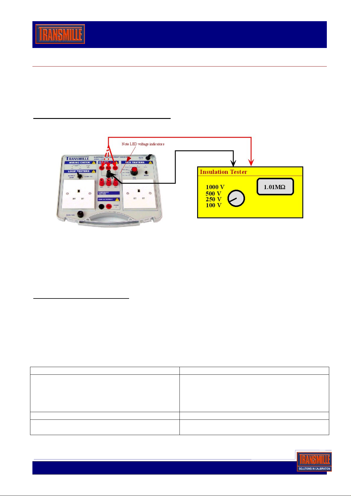
1: To check the applied test voltage, connect the 2080,s ‘Common’ & ‘1Mohm’ terminals to the
insulation tester as shown below, and plug in 2080 to mains power.
Using the 2080
2: Select the lowest test voltage range on the tester, 100V or 250V, and press test button on the
tester. Note the corresponding Voltage LED on the 2080 lights. Record result as pass on the check
sheet. Check the other test voltage ranges in the same way.
NOTE; For the LEDs to light the red terminal on the 2080 must be positive. On some
testers (eg. Robin) the Red lead is negative, and the leads must be reversed.
Checking the reading accuracy
1: Connected as above, select 500V test voltage range and record the reading on the tester.
Allow from 0.95 MOhms to 1.05 MOhms ± 1 digit *
2: Connect the tester to the 9.9M terminal on the 2080, Starting with the lowest voltage range,
record the displayed reading on each range.
Allow from 9.4 MOhms to 10.4 MOhms ± 1 digit *
3: Connect the tester to the 99M terminals on the 2080, select the 500V range and record the
reading.
Allow from 94 MOhms to 104 MOhms.*
Common Problems Solution
Test voltage LED’s do not light 1: 2080 not plugged in
2: Tests leads reversed (see section 2 above)
3: Test leads open circuit. Try shorting together
to read zero
4: Tester Faulty or low batteries
Only the lower Test Voltage LED on Low batteries in tester
Tester reads over range all the time Test leads open circuit. Note some testers
require the correct test leads to be used.
Page 1 of 5
Application Note - 2080 User Guide.doc • V1.10
Testing 16th Edition Instruments
Testing the Continuity measurement Function
The Continuity, or low resistance function measures low resistance, measured in ohms.
To check the accuracy of this function the 2080 has 3 precision low value resistors. Note that the
tester will also measure the resistance of the test leads and connections as well. Many testers have a
null function to ‘zero’ out this lead resistance before making a measurement. Please see the
instructions for your tester on how to use this function.
1: First Null out test leads. If your tester does not have a null function note the reading obtained with
the test leads shorted together and take this reading off all other readings.
Using the 2080
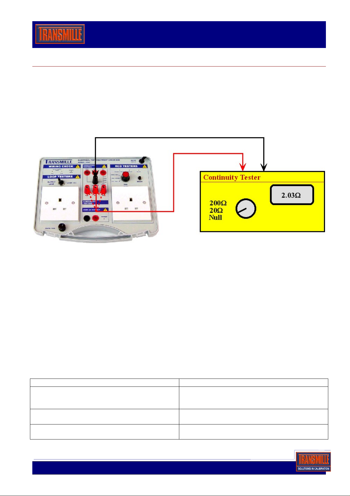
2: Connect the test leads to the ‘common’ and the ‘0.5 Ohms’ terminals as shown above.
Select the lowest range on the tester & record the reading displayed on the tester.
Allow readings from 0.4 Ohms to 0.6 Ohms ± 1 digit.*
3: Connect the test leads to the ‘common’ and the ‘2 Ohms’ terminals. Select the range**, and record
the reading.
Allow readings from 1.85 Ohms to 2.15 Ohms ± 1 digit.*
4: Connect the test leads to the ‘common’ and the ’10 Ohms’ terminals. Select the range**, and
record
the reading.
Allow readings from 9.75 Ohms to 10.25 Ohms ± 1 digit.*
** Select the range on the tester so as to take one reading from each range on the tester.
For example if the tester had a 2 Ohm, 20 Ohm & 200 Ohm range use the 2 Ohm to measure
0.5 Ohm, the 20 Ohm range to measure 2 Ohm & the 200 Ohm range to measure 10 Ohm.
Common Problems Solution
Tester reads over range The test leads are open circuit. Note some test
leads are fused and some use special
connectors. Check leads are OK
Reading unstable Check connections are clean and tight in the
sockets
Reading High Checked Tester is zeroed correctly with leads
shorted together. Poor leads will give a high zero
Page 2 of 5
Application Note - 2080 User Guide.doc • V1.10
 Loading...