

Transmille 1000 Calibration Guide

1000 Series
Precision Multi Product Calibrator
Calibration Manual
TRANSMILLE LTD. Version 1 : Jul 2015 Page 1

1000 SERIES CALIBRATION MANUAL
TABLE OF CONTENTS
PREPARING FOR CALIBRATION ................................................................................................................ 3
INTRODUCTION .................................................................................................................................................. 3
EQUIPMENT REQUIRED ...................................................................................................................................... 3
OPTIONAL EQUIPMENT ...................................................................................................................................... 4
CALIBRATION PASSWORD ........................................................................................................................... 5
CHANGING THE CALIBRATION PASSWORD ........................................................................................................ 5
SET NEW PASSWORD ......................................................................................................................................... 7
MANUAL CALIBRATION ................................................................................................................................ 9
ENTERING CALIBRATION MODE ...................................................................................................................... 10
EXITING CALIBRATION MODE ......................................................................................................................... 12
CALIBRATION PARAMETERS .................................................................................................................... 13
CONNECTIONS ............................................................................................................................................... 14
CALIBRATION OF RANGES ........................................................................................................................ 15
D.C. VOLTAGE ................................................................................................................................................ 15
D.C. CURRENT ................................................................................................................................................ 19
A.C. VOLTAGE ................................................................................................................................................ 24
A.C. CURRENT ................................................................................................................................................ 28
PASSIVE Ω ....................................................................................................................................................... 33
ACTIVE Ω ........................................................................................................................................................ 36
CAPACITANCE ................................................................................................................................................. 40
A/D INPUT ....................................................................................................................................................... 43
CONTINUITY RESISTANCE CURRENT ............................................................................................................... 46
THERMOCOUPLE .............................................................................................................................................. 48
VERIFICATION OF RANGES ....................................................................................................................... 51
DC VOLTAGE .................................................................................................................................................. 51
AC VOLTAGE .................................................................................................................................................. 54
DC CURRENT .................................................................................................................................................. 56
AC CURRENT .................................................................................................................................................. 58
PASSIVE RESISTANCE ...................................................................................................................................... 60
ACTIVE RESISTANCE ....................................................................................................................................... 61
CAPACITANCE (MEASURED AT 1 KHZ) ............................................................................................................ 63
FREQUENCY OUTPUT ....................................................................................................................................... 64
A/D INPUT ....................................................................................................................................................... 65
THERMOCOUPLE COLD JUNCTION MEASUREMENT .......................................................................................... 66
TEMPERATURE SIMULATION............................................................................................................................ 66
SIMULATED PRT ............................................................................................................................................. 70
CONTINUITY RESISTANCE (OPTIONAL) ............................................................................................................ 71
CONTINUITY CURRENT (OPTIONAL) ................................................................................................................ 72
INSULATION TEST FUNCTION (OPTIONAL) ....................................................................................................... 73
TRANSMILLE LTD. Version 1 : Jul 2015 Page 2

1000 SERIES CALIBRATION MANUAL
Preparing For Calibration
Introduction
The recommended calibration period for the 1000 series calibrators is 12 months.
Extended specifications for 6, 12 and 24 month re-calibration periods are available
from the 1000 series extended specifications.
Calibration can be achieved using one of two methods:
1. Manual calibration via the front panel controls.
2. Automated closed-loop calibration using ProCal calibration software.
In both instances the calibrator should be switched on and allowed to warm up for
the required period as stated in the operator’s manual (see “Powering up the
calibrator”, p15 of the 100 series operation manual). Calibration should be performed
in a stable environment where the temperature is stable to within +/- 1ºC during the
calibration.
Equipment Required
To calibrate the 1000 series calibrators the following equipment is required:
1. High Accuracy precision Multimeter (example Transmille 8081 / Agilent 3458A
opt 002 / Fluke 8508A)
2. LCR Bridge (example Agilent)
3. DC Voltage Source (example Transmille 3000 series multiproduct calibrator,
Fluke 55xx series multiproduct calibrator)
4. High Accuracy Frequency Counter / GPS Frequency Reference / Off-Air
Frequency Reference
Between these four pieces of equipment it is possible to calibrate all basic functions
of the 1000 series calibrators. For units fitted with additional options additional
equipment is required.
TRANSMILLE LTD. Version 1 : Jul 2015 Page 3

1000 SERIES CALIBRATION MANUAL
Optional Equipment
To perform a full calibration of a 1000 series multiproduct calibrator additional
equipment may be required dependent upon the capabilities of the multimeter being
used.
For multimeters such as the Agilent 3458A with limited maximum current, a selection
of current shunts are required. These current shunts should be suitable for both DC
and AC current up to. Suggested current shunt values are listed below, along with
the current range they will be used for :
0.1 Ohm – 1A to 10A AC/DC
1 Ohm – 100 mA to 1A AC/DC
10 Ohm – 10.2mA to 100mA AC/DC
100 Ohm –1.02mA to 10mA AC/DC
These shunts are also used for multimeters with insufficient current accuracy for low
current calibration.
TRANSMILLE LTD. Version 1 : Jul 2015 Page 4
1000 SERIES CALIBRATION MANUAL
Calibration Password
Changing the Calibration Password
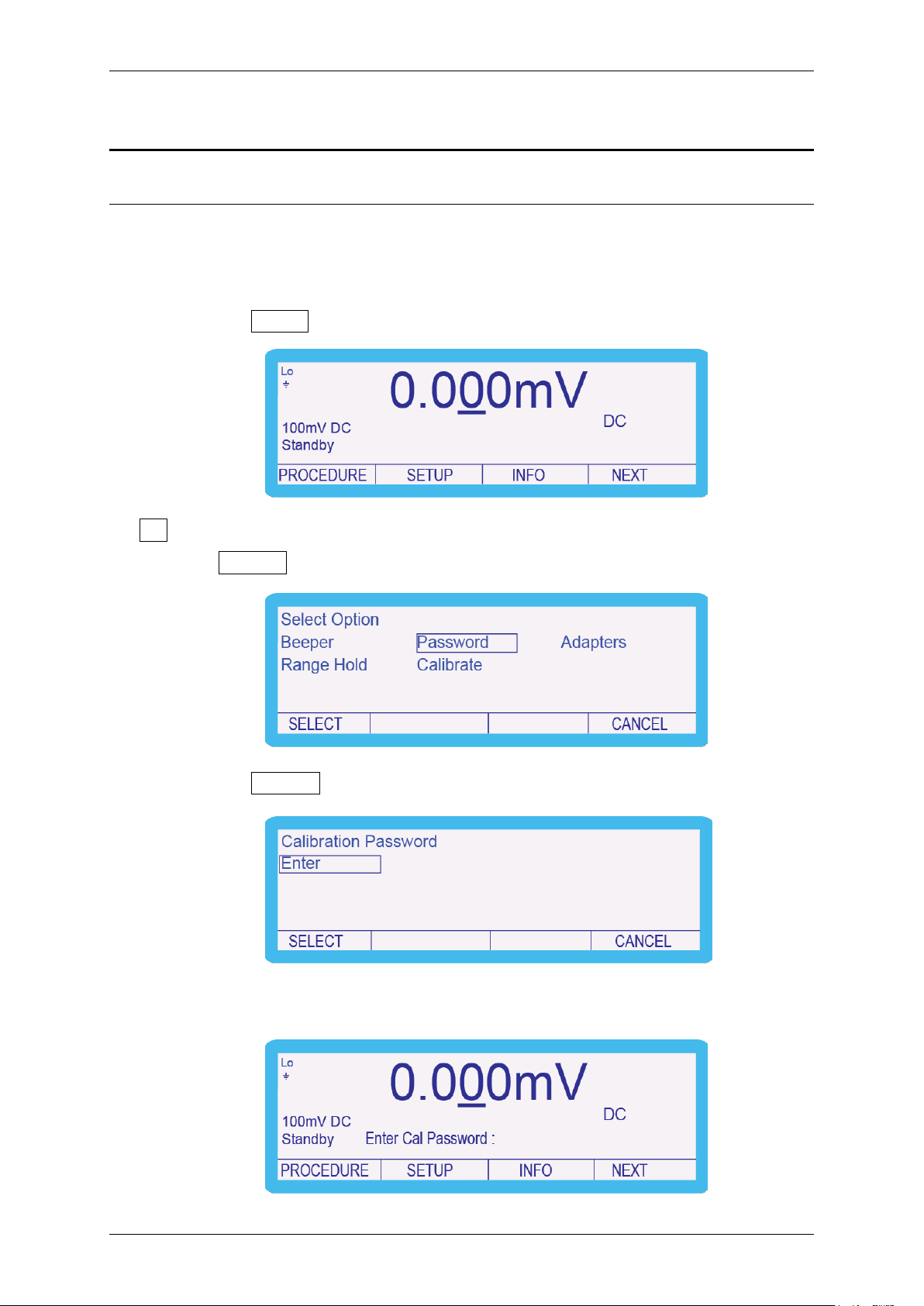
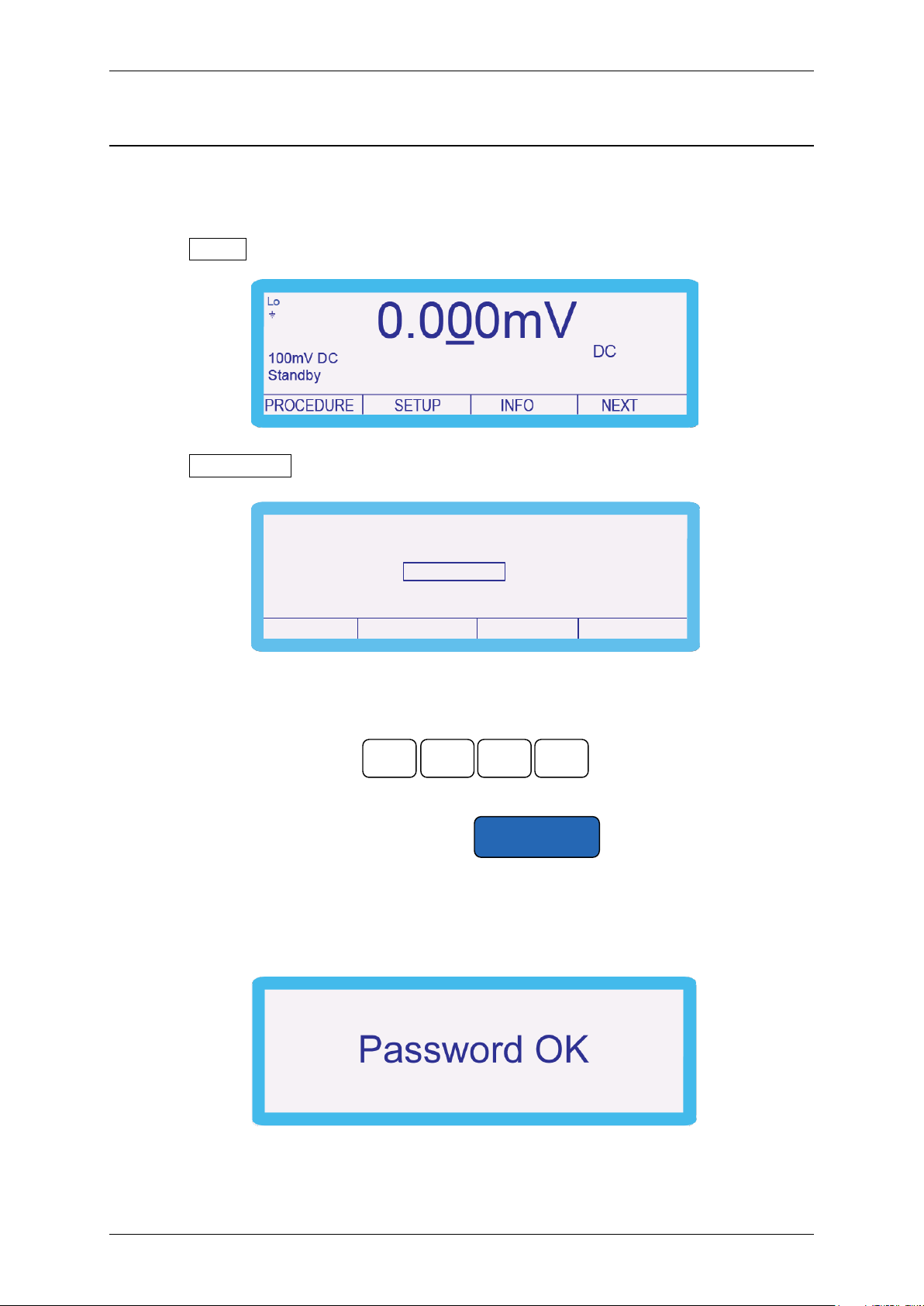
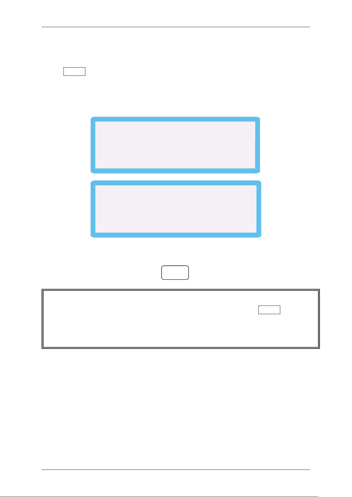
To navigate to the ‘Calibration Password’ screen follow the procedure in the section:
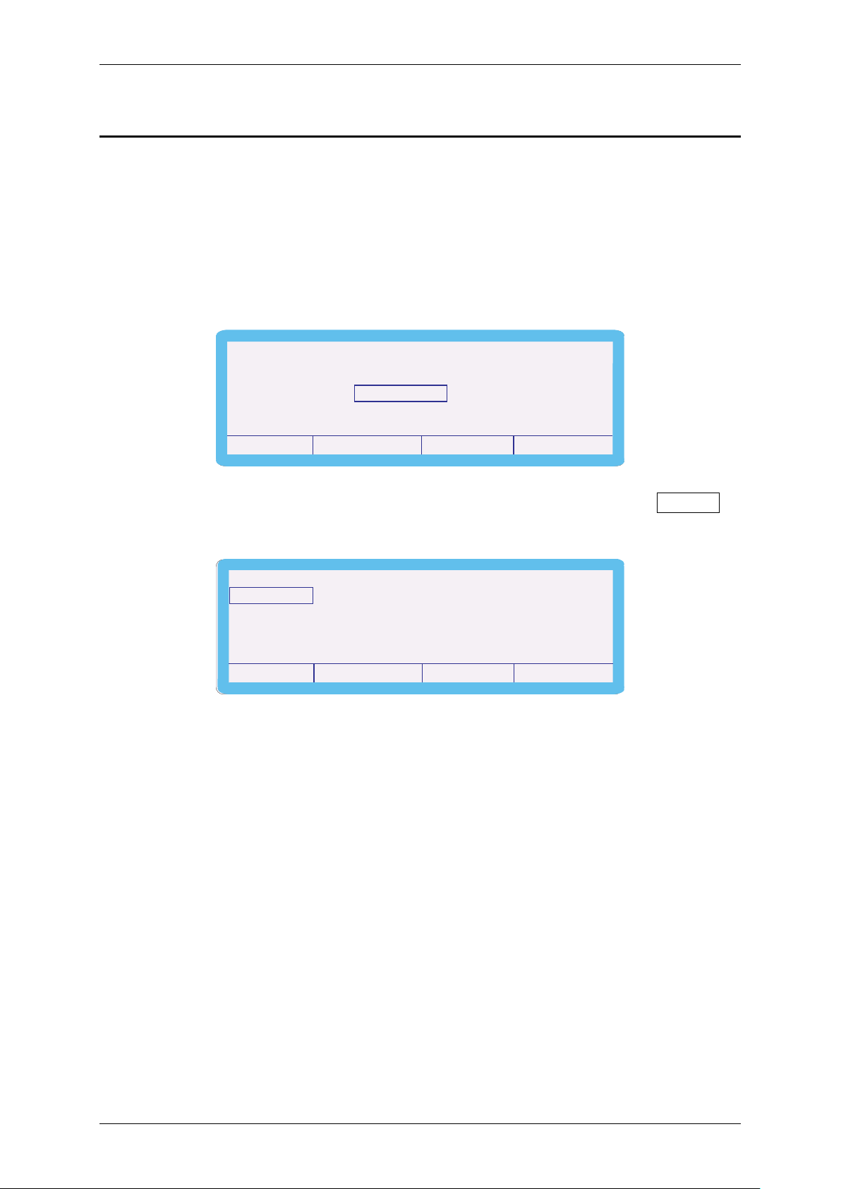
‘Manual Calibration’ to step 3 where the following screen appears:
1. Press the SETUP soft key.
2. Use the ‘Digital Control’ or the ‘Arrow Keys’ to highlight ‘Password’ and then
press SELECT soft key.
3. Press the SELECT soft key.
4. Enter the calibration password (default 0324).
TRANSMILLE LTD. Version 1 : Jul 2015 Page 5
1000 SERIES CALIBRATION MANUAL
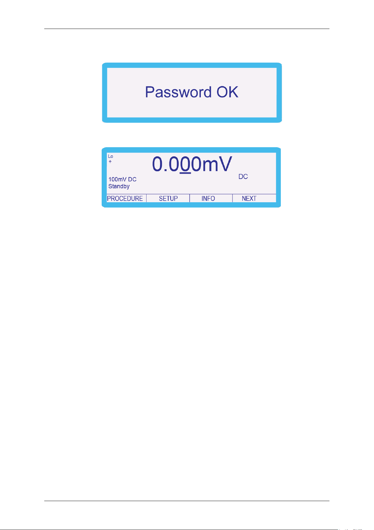
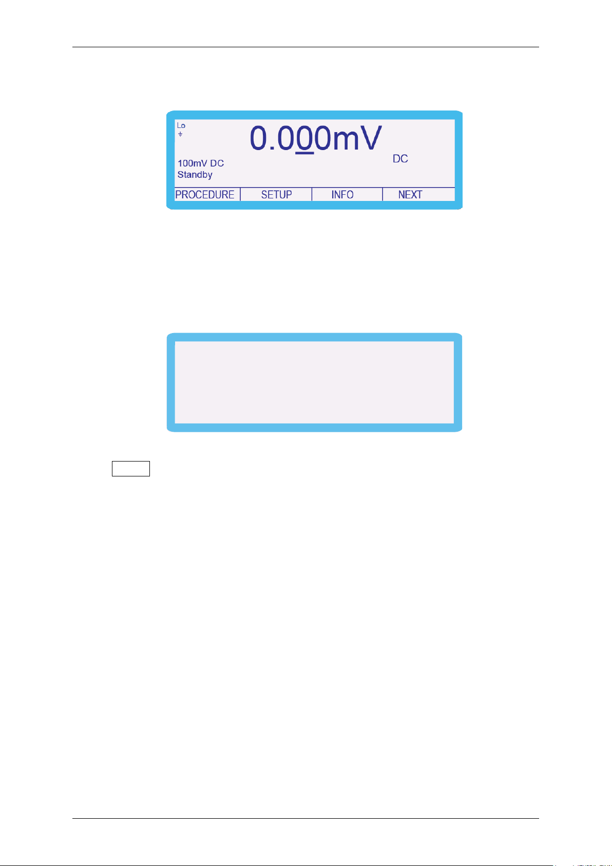
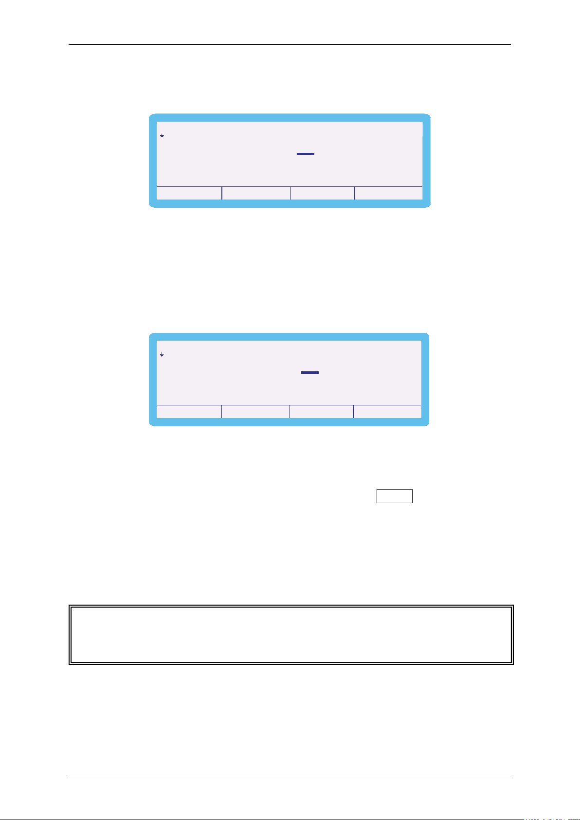
The following screen is displayed for approximately 2 seconds:
and then reverts back to:
The instrument is now ready to be calibrated and the password can be changed.
TRANSMILLE LTD. Version 1 : Jul 2015 Page 6
1000 SERIES CALIBRATION MANUAL
1 0 0
0
Calibration Password
CANCEL SELECT
Enter Set End Cal
0.000mV
Standby
DC
Lo
SETUP NEXT
100mV DC
INFOPROCEDURE
Enter New Cal Password :
Set New Password
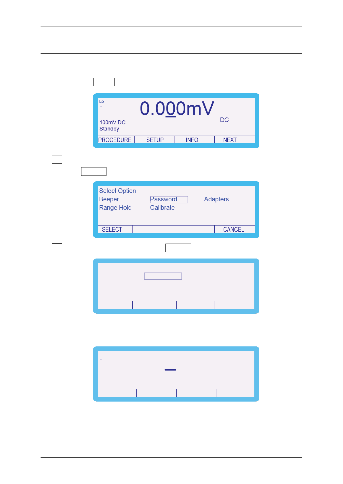
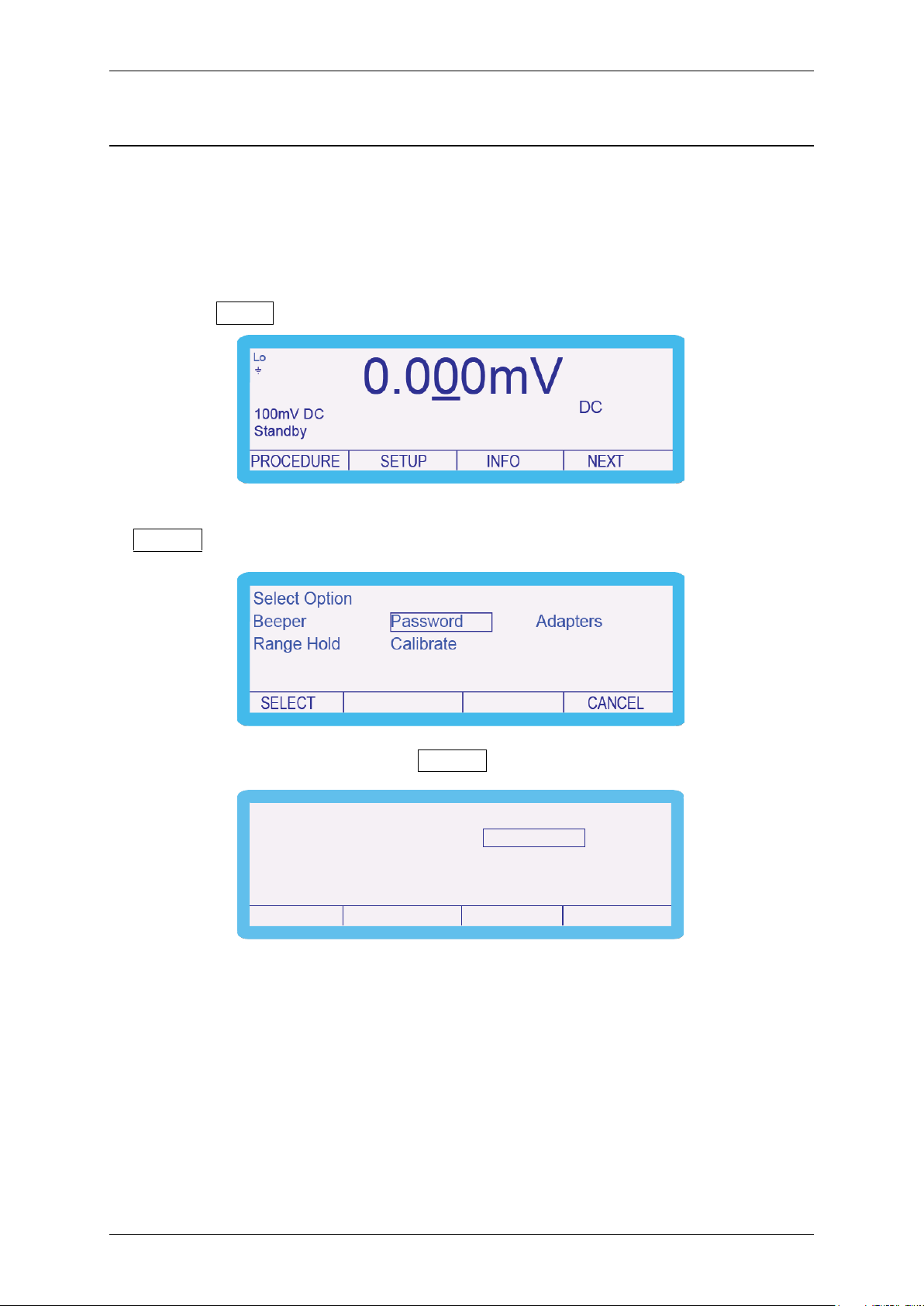
To change the password, complete the following procedure:
1. Press the SETUP soft key.
2. Use the ‘Digital Control’ or the ‘Arrow Keys’ to highlight ‘Password’ and then
press SELECT soft key.
3. Highlight ‘Set’ and then press the SELECT soft key.
4. ‘Enter New Cal Password’ using function control keys, followed by the ENTER
key e.g. 1000.
TRANSMILLE LTD. Version 1 : Jul 2015 Page 7
1000 SERIES CALIBRATION MANUAL
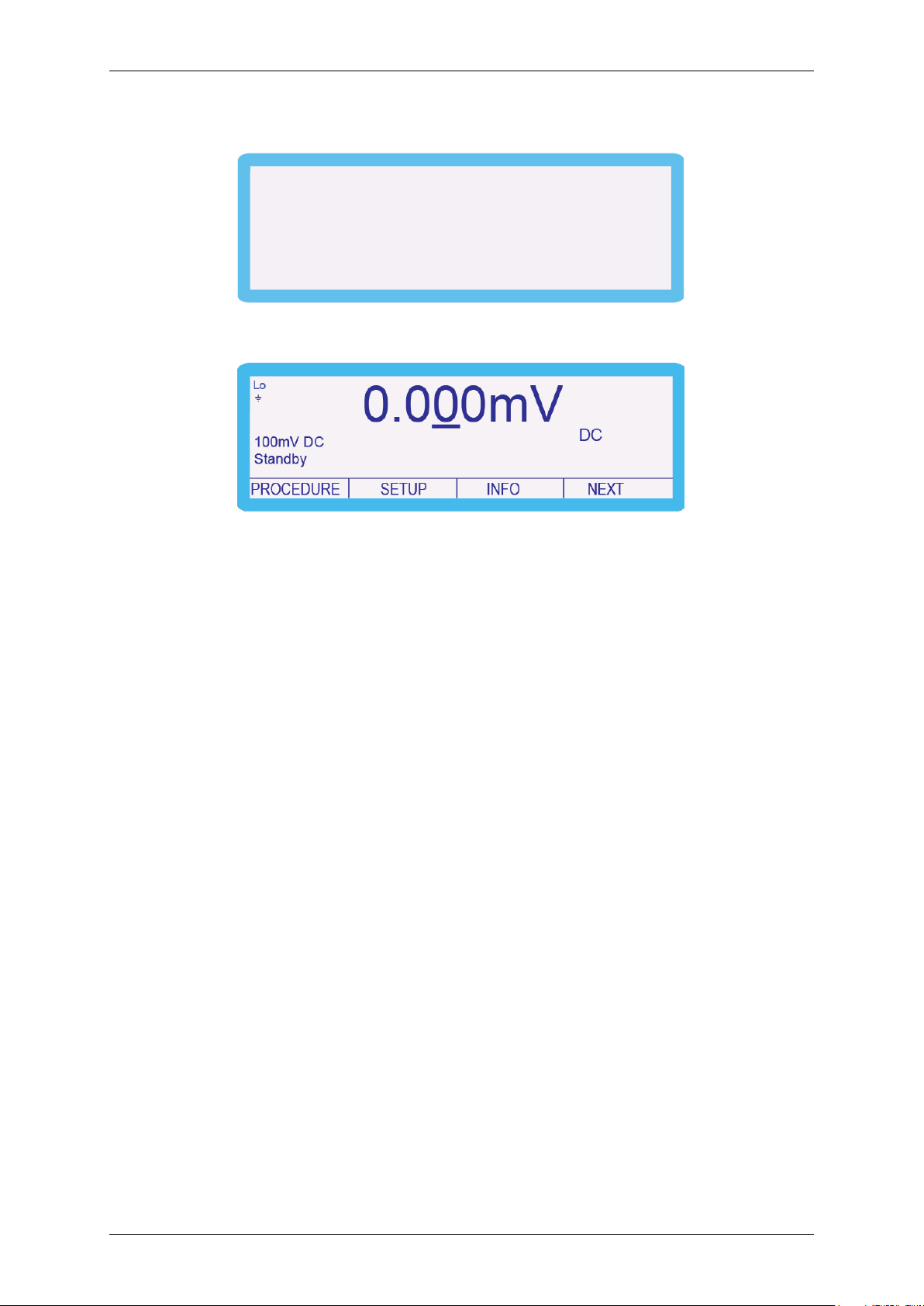
Password Set
The following screen is displayed for approximately 2 seconds:
and then reverts to:
The password has now been changed.
TRANSMILLE LTD. Version 1 : Jul 2015 Page 8
1000 SERIES CALIBRATION MANUAL
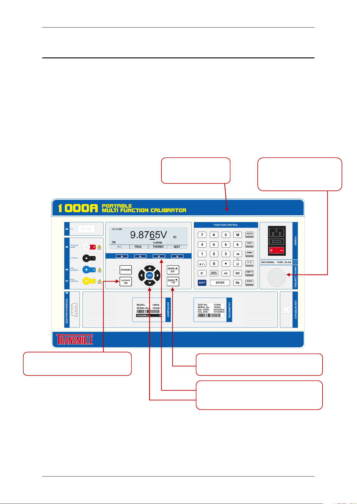
Function Control
1. Adjusts calibrator output
2. Enter ‘cal factors’
Digital Control
3. Adjusts calibration factors
Output On key –
Standby key – switches output off
Range keys
1. Changes calibration reference point on each range
Soft and Arrow keys
2. Change parameter and range (arrow)
Manual Calibration
Manual Calibration is achieved using the following front panel controls:
1. A digital control scroll wheel
2. Function controls
3. Soft and Arrow keys
4. Range up and Down keys
5. Output On and Standby keys
1. Adjusts calibrator output
2. Selects calibrator ranges
switches output on
TRANSMILLE LTD. Version 1 : Jul 2015 Page 9
1. Select parameter, range, store, undo & exit – (soft)
1000 SERIES CALIBRATION MANUAL
0 3 2
4
Select Option
CANCEL SELECT
Beeper Password Adapters
Range Hold Calibrate
ENTER
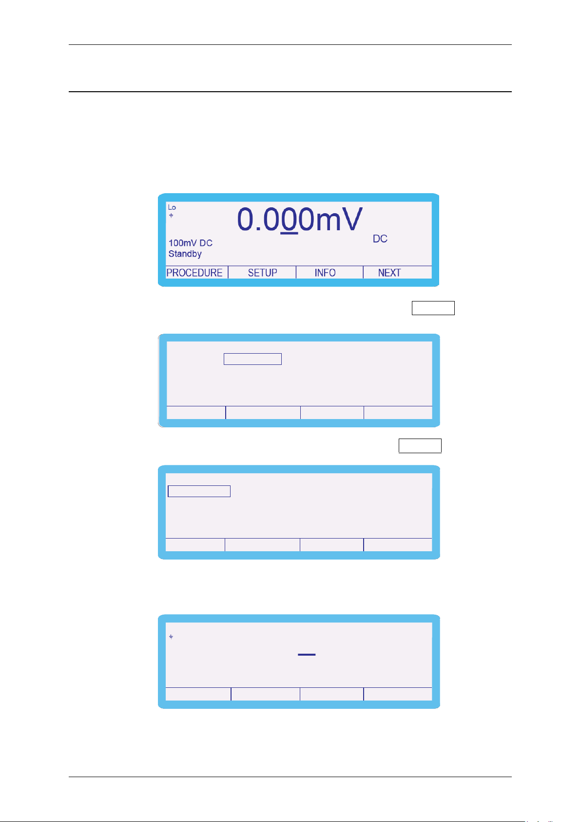
Entering Calibration Mode
To navigate to the calibration control screen, complete the following procedure:
1. Select SETUP using the soft key.
2. Select CALIBRATE using the soft key.
3. ‘Enter Cal Password’ using function control keys.
(0324 is the default password) followed by
The following screen is displayed for approximately 2 seconds:
TRANSMILLE LTD. Version 1 : Jul 2015 Page 10
1000 SERIES CALIBRATION MANUAL
Password Incorrect
and then reverts to:
The instrument is now ready to be calibrated.
Should the password be entered incorrectly, the screen will display the following
message for approximately 2 seconds:
Select SETUP using the soft key to navigate back to ‘Enter Cal Password’ screen
and re-enter the password.
TRANSMILLE LTD. Version 1 : Jul 2015 Page 11
1000 SERIES CALIBRATION MANUAL
Calibration Password
CANCEL SELECT
Enter Set End Cal
Exiting Calibration Mode
After calibration of the 1000 series is complete the calibration program should be
ended to avoid any unauthorised or mistaken adjustment of the calibrator.
The following procedure should be completed.
1. Press the SETUP soft key.
2. Use the ‘Digital Control’ or the ‘Arrow Keys’ to highlight ‘Password’ and then press
SELECT soft key.
3. Highlight ‘End Cal’ and then press SELECT soft key.
The calibrator then returns to the normal screen.
TRANSMILLE LTD. Version 1 : Jul 2015 Page 12
1000 SERIES CALIBRATION MANUAL
Select Option
CANCEL SELECT
Beeper Password Adapters
Range Hold Calibrate
Select Function
CANCEL SELECT
DC Volts
Passive Ω
DC Amps AC Volts
AC Amps
Active Ω
Capacit. A/D Input
ThermoC
Ins Test
Cont I
Calibration Parameters
With the calibration password entered the different parameters of the instrument can
be calibrated.
To enter a different parameter, complete the following procedure:
1. Enter the setup menu and use the ‘Digital Control’ or the ‘Arrow Keys’ to
select ‘Calibrate’.
2. Highlight the required parameter e.g. ‘DC Volts’ and then press the SELECT
soft key.
Depending upon the model and options fitted the available functions will vary.
TRANSMILLE LTD. Version 1 : Jul 2015 Page 13
1000 SERIES CALIBRATION MANUAL
DC & AC Voltage, Passive
Continuity, Capacitance
DC & AC Current up to and
including the 1A range
DC & AC Current up to and
including the 10A range
Simulated PRT
Thermocouple Output
A/D Input
Pin 9 - Input
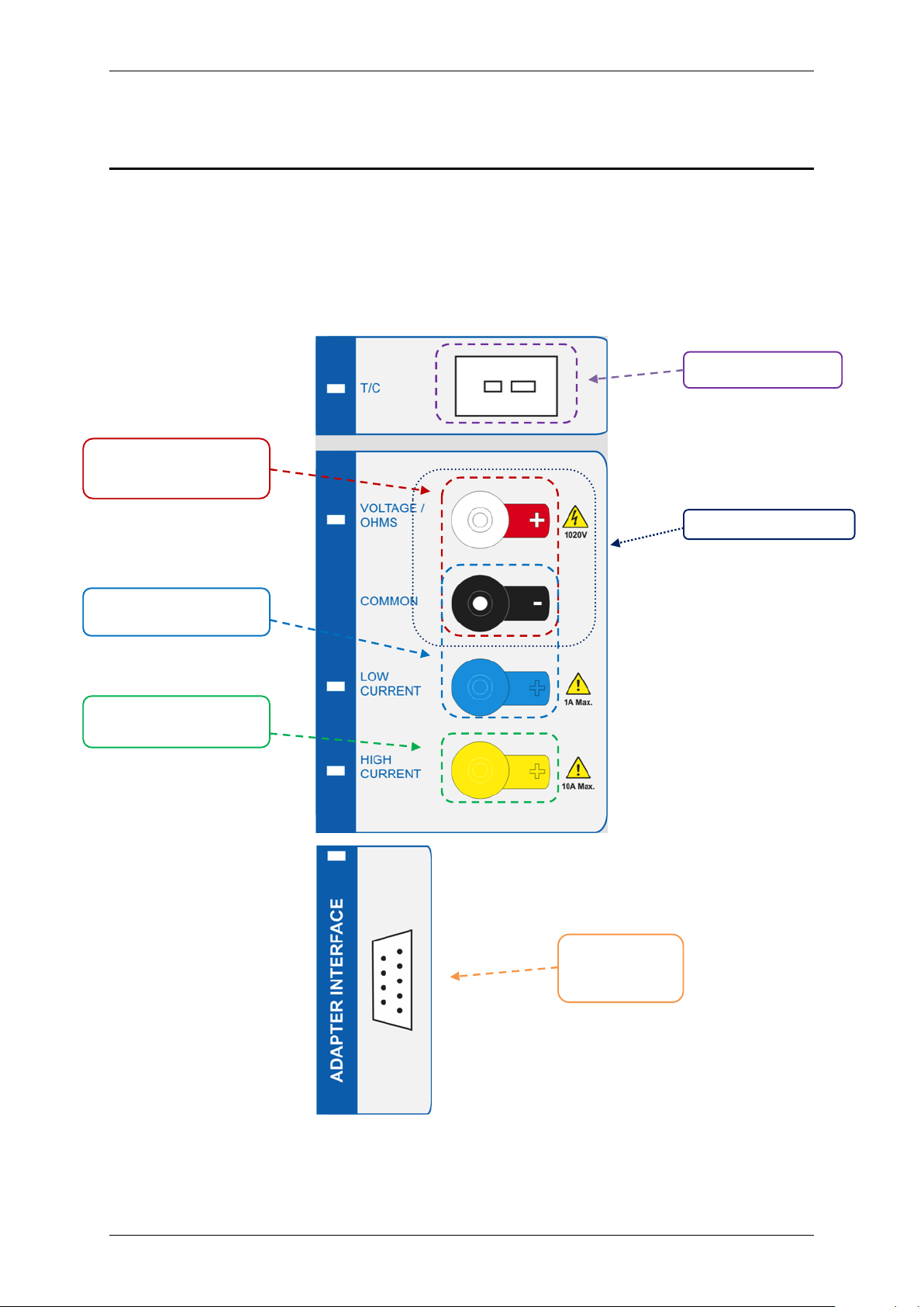
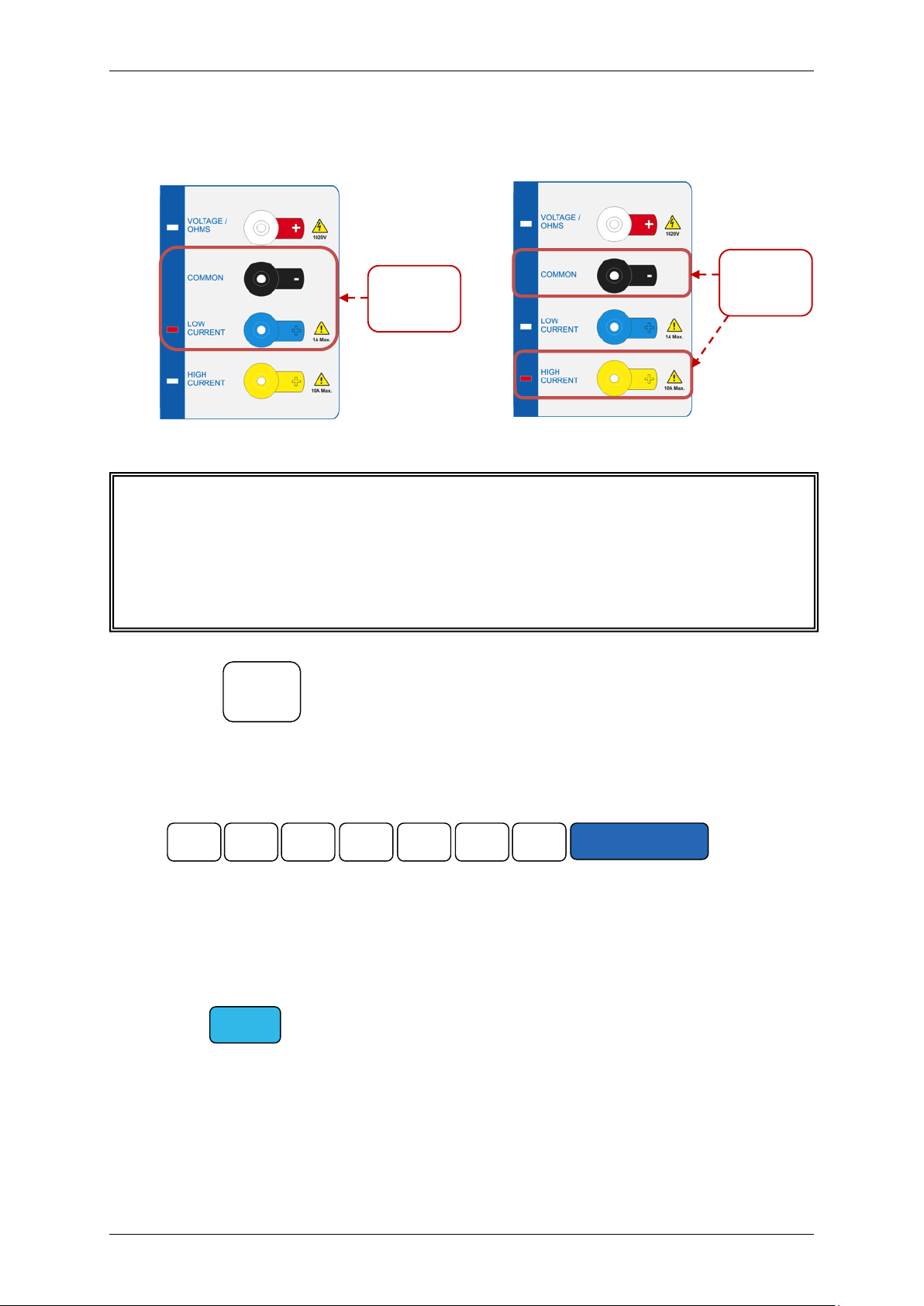
Connections
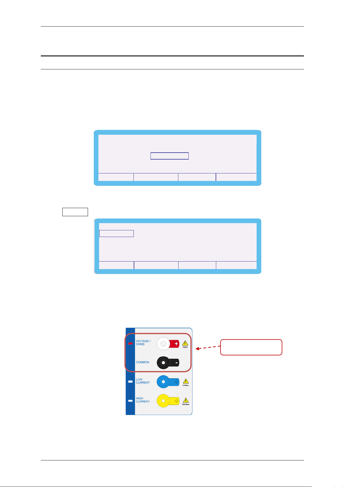
The output of the 1000 series calibrator should be connected to the precision
multimeter as below:
& Active , Frequency,
Pin 7 – ground
TRANSMILLE LTD. Version 1 : Jul 2015 Page 14
1000 SERIES CALIBRATION MANUAL
Output voltage terminals
Select Option
CANCEL SELECT
Beeper Password Adapters
Range Hold Calibrate
Select Function
CANCEL SELECT
DC Volts
Passive Ω
DC Amps AC Volts
AC Amps
Active Ω
Capacit. A/D Input
ThermoC
Ins Test
Cont I
Calibration of Ranges
D.C. Voltage
To calibrate the D.C. Voltage parameter, complete the procedure as follows:
1. Enter the setup menu and use the ‘Digital Control’ or the ‘Arrow Keys’ to
select ‘Calibrate’.
2. Highlight the required parameter; ‘DC Volts’ for example, and then press the
SELECT soft key.
3. Connect the calibrator output voltage terminals to the precision Multimeter.
Ensure that the Multimeter has been zeroed as a system by shorting out the
leads and pressing the null button.
TRANSMILLE LTD. Version 1 : Jul 2015 Page 15
1000 SERIES CALIBRATION MANUAL
SHIFT
OUTPUT
ON
0 • 0 0 0 2 8
ENTER
Select Range
CANCEL SELECT
100 mV DC
1 kV DC
1 V DC 10 V DC 100 V DC
20.000mV
Standby
DC
Lo
NEXT
100mV DC
Zero Calibration
100mV DC
PROCEDURE SETUP INFO
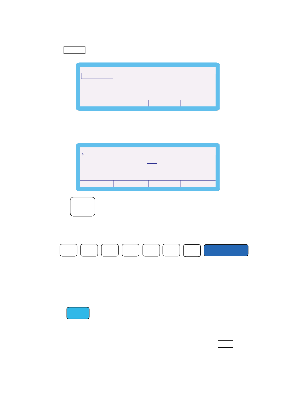
4. Select required range using the ‘Digital Control’ or the ‘Arrow Keys’ and press
the SELECT soft key.
5. Ensure the calibration point is set to ‘Zero Calibration’. Use the ‘range up’ and
‘range down’ keys to change the calibration point if required.
6. Press and measure the output ‘Zero Calibration’.
7. To adjust the output, type in the measured value using the keyboard, followed
by the ‘ENTER’ key i.e. 0.00028mV.
8. The output can also be adjusted by moving the ‘cursor’ to the required digit
and adjusting the output using the up and down arrow keys or the digital
control.
9. The key will illuminate to indicate that a change has been made
to the calibration of the instrument, however has not yet been stored.
10. To undo the adjustment before storing the changes, press the UNDO soft key.
This will remove any changes that have been made to the output of the
calibrator.
TRANSMILLE LTD. Version 1 : Jul 2015 Page 16
1000 SERIES CALIBRATION MANUAL
SHIFT
NOTE: All calibration points can be adjusted prior to storing the calibration
factors. However, if the calibration routine is ended before the STORE button
has been pressed, due to a power failure for example, the new calibration
factors will not be saved.
Storing ....
Calibration Stored
11. Once the output has been adjusted to within specification, the changes can be
stored to long term memory. To store the changes permanently, press the
STORE soft key.
The following 2 screens are displayed briefly to confirm that the calibration
factors have been saved.
After displaying these messages, the shift key will also cease to be illuminated:
TRANSMILLE LTD. Version 1 : Jul 2015 Page 17
1000 SERIES CALIBRATION MANUAL
100.000mV
Standby
DC
Lo
NEXT
100mV DC
Positive Full Scale
100mV DC
PROCEDURE SETUP INFO
NOTE: The ‘Zero Calibration’ points for both the 200V DC and 1kV DC
Ranges do not occur at 0V. They take place at 5V and 50V respectively.
-100.000mV
Standby
DC
Lo
NEXT
100mV DC
Negative Full Scale
100mV DC
PROCEDURE SETUP INFO
12. Using the Range up / Range down’ keys, change the output to ‘Positive Full
Scale’
13. Measure the output, and adjust as required using the process described in
steps 6 – 10.
14. Use the Range up / Range down keys to change the calibration point to
‘Negative Full Scale’.
15. Measure the output, and adjust as required using the process described in
steps 6 – 10.
16. When calibration of this range is complete press the RANGE soft key.
17. To continue adjusting other ranges in the DC Voltage function, select ‘DC
Volts’ and select the required range.
18. All DC volts ranges are calibrated in the same manner.
TRANSMILLE LTD. Version 1 : Jul 2015 Page 18
1000 SERIES CALIBRATION MANUAL
Select Function
CANCEL SELECT
DC Volts
Passive Ω
DC Amps AC Volts
AC Amps
Active Ω
Capacit. A/D Input
ThermoC
Ins Test
Cont I
Select Range
CANCEL SELECT
100 µA DC
1 A DC
1 mA DC 10 mA DC 100 mA DC
10 A DC
20.000mV
Standby
DC
Lo
NEXT
100µA DC
Zero Calibration
100µA DC
PROCEDURE SETUP INFO
D.C. Current
To calibrate the D.C. Current parameter, complete the procedure as follows:
1. Enter the setup menu and use the ‘Digital Control’ or the ‘Arrow Keys’ to select
‘Calibrate’.
2. Highlight the required parameter ‘DC Amps’ and then press SELECT soft key.
3. Highlight the required range e.g. ‘100µA’ and then press SELECT soft key.
4. The Calibrator will now change to the 100µA AC range. Use the Range Up /
Range Down keys to select the ‘Zero Calibration’ adjustment point.
TRANSMILLE LTD. Version 1 : Jul 2015 Page 19
1000 SERIES CALIBRATION MANUAL
OUTPUT
ON
Low output
terminals
High
current
SHIFT
NOTE: Ensure that the correct terminals / current shunts are used for the
various current outputs. The 1000 calibrators can output up to 10A DC
current, which can blow the fuse / cause damage if the incorrect input is
used.
0 . 0 0 0 2 8
ENTER
5. Connect the calibrator output voltage terminals to the precision multimeter.
Ensure that the multimeter is in AC Current on the appropriate range.
current
6. Press and measure the output.
output
7. To adjust the output, type in the measured value using the keyboard, followed
by the ‘ENTER’ key i.e. 0.00028uA.
8. The output can also be adjusted by moving the ‘cursor’ to the required digit
and adjusting the output using the up / down arrows or the digital control.
9. The key will illuminate to indicate that a change has been made
to the calibration of the instrument, however has not yet been stored.
TRANSMILLE LTD. Version 1 : Jul 2015 Page 20
1000 SERIES CALIBRATION MANUAL
SHIFT
Storing ....
Calibration Stored
NOTE: All calibration points can be adjusted prior to storing the calibration
factors. However, if the calibration routine is ended before the STORE button
has been pressed, due to a power failure for example, the new calibration
factors will not be saved.
10. To undo the adjustment before storing the changes, press the UNDO soft key.
This will remove any changes that have been made to the output of the
calibrator.
11. Measure and check the output again and then press STORE soft key.
The following 2 screens are displayed briefly to confirm that the calibration factors
have been saved.
After displaying these messages, the shift key will also cease to be illuminated:
TRANSMILLE LTD. Version 1 : Jul 2015 Page 21

1000 SERIES CALIBRATION MANUAL
100.000mV
Standby
DC
Lo
NEXT
100mV DC
Positive Full Scale
100mV DC
PROCEDURE SETUP INFO
-100.000mV
Standby
DC
Lo
NEXT
100µA DC
Negative Full Scale
100µA DC
PROCEDURE SETUP INFO
12. Use the ‘range up’ and ‘range down’ keys to change the calibration point to
‘Positive Full Scale’.
13. Measure the output as before; if necessary adjust as previously described
above (steps 5-11).
14. Use the ‘range up’ and ‘range down’ keys to change the calibration point to
‘Negative Full Scale’.
15. Measure the output as before; if necessary adjust as previously described
above (steps 5-11).
16. When calibration of this range is complete press the RANGE soft key. To
continue adjusting other ranges in the DC Amps function, select ‘DC Amps’
and select the required range.
13. All D.C. current ranges are calibrated in the same manner.
TRANSMILLE LTD. Version 1 : Jul 2015 Page 22
 Loading...