

Transmille 1000 User Manual

1000 Series
Precision Multi Product Calibrator
Operation Manual
TRANSMILLE LTD. Version 1.30 Page 1

1000 SERIES OPERATION MANUAL
IMPORTANT NOTICE
THIS CALIBRATOR
WILL
REQUIRE AN
UNLOCK CODE
AFTER THE EVALUATION
PERIOD HAS EXPIRED.
(60 Days after invoice date)
AFTER THE EVALUATION PERIOD HAS EXPIRED THE
OPERATION OF THE CALIBRATOR IS LOCKED AND THE DISPLAY
SHOWS A NUMBER WHICH MUST BE QUOTED TO TRANSMILLE
TO RECEIVE THE UNLOCK CODE
THE UNLOCK CODE IS AVAILALBLE
FROM TRANSMILLE
ONLY AFTER PAYMENT
HAS BEEN RECEIVED.
This code only needs to be entered once
in the life of the instrument.
Please contact Transmille or use the form in the
back of the manual to obtain the unlock code.
Transmille Ltd.
Staplehurst, Kent.
Tel: 44 (0)1580 890700 Fax: 44(0)1580 890711
Email: sales@transmille.com
TRANSMILLE LTD. Version 1.30 Page 2

1000 SERIES OPERATION MANUAL
DECLARATION OF CONFORMITY
Manufacturer’s Name: Transmille Ltd.
Manufacturer’s Address: Unit 4, Select Business Centre
Lodge Road
Staplehurst
TN12 0QW
Declares, that the product
Product Name: Multi-product Calibrator
Model Number: 1000A / 1000B
Product Options: This declaration covers all options of the above product(s)
Conforms with the following European Directives:
The product herewith complies with the requirements of the Low Voltage
Directive 73/73EEC and the EMC Directive 89/336/EEC (including 93/68/EEC)
and carries the CE Marking accordingly
Conforms with the following product standards:
EMC
EN 61326-1:1997+A1:1998 • EN55011:1991 (Group 1 : Class A)
Standard Limit
IEC 61000-4-2:1995+A1:1998 / EN 61000-4-2:1995 4kV CD, 8kV AD
IEC 61000-4-3:1995 / EN 61000-4-3:1995 3 V/m, 80-1000 MHz
IEC 61000-4-4:1995 / EN 61000-4-4:1995 0.5kV signal lines, 1kV power lines
IEC 61000-4-5:1995 / EN 61000-4-5:1995 0.5kV line-line, 1kV line-ground
IEC 61000-4-6:1996 / EN 61000-4-6:1996 3V, 0.15-80 MHz / cycle, 100%
IEC 61000-4-11:1994 / EN 61000-4-11:1994 Dips: 30% 10ms; 60% 100ms
Interrupt > 95%@5000ms
SAFETY
IEC 61010-1:1990+A1:1992+A2:1995 / EN 61010-1:1993+A2:1995
01/07/2013
Revision No: 1.0 Managing Director
Date: 01/07/2013
TRANSMILLE LTD. Version 1.30 Page 3

1000 SERIES OPERATION MANUAL
TABLE OF CONTENTS
1000 SERIES CALIBRATION INTRODUCTION .......................................................................................... 6
MAIN FEATURES ................................................................................................................................................ 6
ACCURACY AND FUNCTIONALITY ..................................................................................................................... 7
TRUE MULTIPRODUCT CALIBRATION ................................................................................................................ 7
USB INTERFACE ................................................................................................................................................ 7
OUTPUT CONNECTION INDICATION ................................................................................................................... 7
PREPARING THE CALIBRATOR FOR USE. ............................................................................................... 8
INITIAL INSPECTION. .......................................................................................................................................... 8
LIFTING AND CARRYING THE CALIBRATOR ....................................................................................................... 8
POSITIONING THE CALIBRATOR ......................................................................................................................... 9
POWER AND INTERFACE CONNECTIONS ........................................................................................................... 10
CHECKING THE LINE VOLTAGE ....................................................................................................................... 11
POWER LINE INLET FUSE AND RATING ............................................................................................................ 11
REPLACING THE POWER LINE FUSE ................................................................................................................. 11
CONNECTING TO A COMPUTER ......................................................................................................................... 13
CONNECTION DETAILS .................................................................................................................................... 13
POWERING UP THE CALIBRATOR ...................................................................................................................... 14
OUTPUT CONNECTIONS ................................................................................................................................... 15
OUTPUT OVERLOADS ...................................................................................................................................... 16
OPERATION ..................................................................................................................................................... 17
SAFETY WARNINGS ......................................................................................................................................... 17
INTRODUCTION TO OPERATION ....................................................................................................................... 17
FRONT PANEL CONTROLS AND INDICATORS .................................................................................................... 18
GRAPHIC LCD DISPLAY .................................................................................................................................. 19
FRONT PANEL KEYBOARD ............................................................................................................................... 20
DIGITAL CONTROL AND CURSOR KEYS ........................................................................................................... 22
TERMINAL STATUS LED’S ............................................................................................................................... 22
9 PIN ADAPTER INTERFACE CONNECTOR. ....................................................................................................... 25
SOFT KEY MENUS .......................................................................................................................................... 26
MENU STRUCTURE .......................................................................................................................................... 26
PROCEDURE MENU .......................................................................................................................................... 27
SETUP MENU ................................................................................................................................................... 28
CONNECTION DIAGRAMS .......................................................................................................................... 29
DC / AC VOLTAGE .......................................................................................................................................... 29
DC / AC CURRENT – OUTPUTS BELOW 1A ...................................................................................................... 29
DC/AC CURRENT – OUTPUTS ABOVE 1A ........................................................................................................ 30
RESISTANCE .................................................................................................................................................... 30
CAPACITANCE ................................................................................................................................................. 31
FREQUENCY ..................................................................................................................................................... 31
THERMOCOUPLE .............................................................................................................................................. 32
PRT / RTD ...................................................................................................................................................... 32
INSULATION RESISTANCE / TEST VOLTAGE MEASUREMENT ........................................................................... 33
CONTINUITY RESISTANCE / CURRENT MEASUREMENT .................................................................................... 33
SETTING AN OUTPUT ................................................................................................................................... 34
USING THE KEYBOARD .................................................................................................................................... 34
ADJUSTING THE OUTPUT USING THE DIGITAL CONTROL ................................................................................... 35
DISPLAY OF % OR PPM ERROR ......................................................................................................................... 35
SETTING A DC VOLTAGE OUTPUT ................................................................................................................... 36
SETTING A DC CURRENT OUTPUT ................................................................................................................... 38
SETTING AN AC VOLTAGE OUTPUT. ............................................................................................................... 40
SETTING AN AC CURRENT OUTPUT ................................................................................................................. 43
SETTING THE SIMULATED RESISTANCE OUTPUT ............................................................................................. 46
TRANSMILLE LTD. Version 1.30 Page 4

1000 SERIES OPERATION MANUAL
SETTING PASSIVE RESISTANCE OUTPUT .......................................................................................................... 48
SETTING CAPACITANCE OUTPUT ..................................................................................................................... 50
SETTING FREQUENCY OUTPUT. ....................................................................................................................... 52
THERMOCOUPLE SIMULATION ......................................................................................................................... 54
PRT OUTPUT ................................................................................................................................................... 56
EA002 – 2/10/50 TURN COIL ADAPTER (OPTION) ........................................................................................... 58
INSULATION RESISTANCE CALIBRATION (OPTION) .......................................................................................... 61
INSULATION TEST VOLTAGE MEASUREMENT (OPTION) .................................................................................. 63
CONTINUITY RESISTANCE CALIBRATION (OPTION) ......................................................................................... 65
CONTINUITY CURRENT MEASUREMENT [1 OHM] (OPTION) ............................................................................ 67
OUTPUT PROTECTION AND SAFETY FEATURES ................................................................................ 69
WARNING AND OUTPUT OVERLOAD INDICATIONS .......................................................................................... 69
HIGH VOLTAGE TIMEOUT. ............................................................................................................................... 69
HIGH VOLTAGE OUTPUT RAMP ....................................................................................................................... 69
HIGH VOLTAGE CURRENT LIMIT ..................................................................................................................... 70
10 AMP TEMPERATURE CUT-OUT .................................................................................................................... 70
REMOTE PROGRAMMING .......................................................................................................................... 71
USB INTERFACE .............................................................................................................................................. 71
RETURNING TO LOCAL CONTROL .................................................................................................................... 72
PROGRAMMING COMMANDS OVERVIEW ......................................................................................................... 72
RESPONSE CODES ............................................................................................................................................ 73
DC VOLTAGE COMMANDS .............................................................................................................................. 74
AC VOLTAGE COMMANDS .............................................................................................................................. 76
DC CURRENT COMMANDS .............................................................................................................................. 78
AC CURRENT COMMANDS .............................................................................................................................. 80
PASSIVE RESISTANCE COMMANDS .................................................................................................................. 82
CAPACITANCE COMMANDS ............................................................................................................................. 84
SIMULATED RESISTANCE COMMANDS ............................................................................................................. 85
FREQUENCY COMMANDS ................................................................................................................................. 86
THERMOCOUPLE SIMULATION COMMANDS ..................................................................................................... 88
TECHNICAL DESCRIPTION ........................................................................................................................ 91
GENERAL ......................................................................................................................................................... 91
INTERNAL FUSES ............................................................................................................................................. 92
OPENING THE CASE ......................................................................................................................................... 93
ACCESS TO INTERNAL FUSES ........................................................................................................................... 94
GETTING THE BEST OUT OF THE CALIBRATOR. ................................................................................................. 95
CALIBRATION AND MAINTENANCE ....................................................................................................... 97
GENERAL ......................................................................................................................................................... 97
ELECTRICAL SAFETY TESTS ............................................................................................................................ 97
CLEANING OF THE FAN VENTS ........................................................................................................................ 98
CLEANING THE EXTERNAL CASE ...................................................................................................................... 98
CALIBRATION .................................................................................................................................................. 99
GUARANTEE AND SERVICE ............................................................................................................................ 100
APPENDIX A .................................................................................................................................................. 102
INSTALLING THE USB INTERFACE DRIVER (WINDOWS XP) .......................................................................... 102
INSTALLING THE USB INTERFACE DRIVER (WINDOWS VISTA / 7)................................................................. 103
CHECKING THE COM PORT SETTING FOR THE USB INTERFACE .................................................................... 104
TRANSMILLE LTD. Version 1.30 Page 5

1000 SERIES OPERATION MANUAL
1000 Series Calibration Introduction
The 1000 series of calibrators offer the smallest and by far the most portable multi
product multi-function calibrator in the world.
Main Features
AC/DC Volts to 1025V
AC/DC Current to 10 Amps
AC/DC Current to 500 Amps with 50 Turn Clamp coil Adapter EA002
Simulated 2 wire Resistance 0 ohms to 10 Mohms
Passive 2 wire Resistance 10 ohms to 100 Mohms
Capacitance 10nF to 1uF
Frequency to 100kHz
PT100 resistance Simulation
Thermocouple Simulation (°C / °F)
USB Interface
Expandable via the Adapter Interface for added functionality
TRANSMILLE LTD. Version 1.30 Page 6

1000 SERIES OPERATION MANUAL
Accuracy and Functionality
The 1000 Series calibrators are available in a rugged portable case or a bench
case. A rack mounting option is also available.
True Multiproduct Calibration
Designed to provide an accurate cost effective portable instrument for the calibration
of multimeters, clamp meters, frequency meters and temperature meters.
Designed for use in the laboratory or portable onsite calibration. The fast warm up
time combined with the small case and low weight make the 1000 series calibrator
also ideal for onsite calibration. The USB interface allows direct connection to a
computer/laptop.
USB Interface
All functions and outputs of the series 1000 calibrator are fully programmable over
the USB interface. The use of the USB interface saves the cost of fitting GPIB cards
to the computer, and also allows easy connection to laptops, reducing the set up
time for on-site calibration.
Output Connection Indication
The output terminal configuration is designed to match the majority of multimeter
input connections, e.g. volts/ohms, low current and high current eliminating the need
for lead changing during calibration. All outputs are isolated when not in use and an
LED indicator shows the active output(s).
TRANSMILLE LTD. Version 1.30 Page 7

1000 SERIES OPERATION MANUAL
Preparing The Calibrator For Use.
Initial inspection.
After shipment the calibrator should be inspected for any signs of external damage.
Should external damage be found contact the carrier immediately. Do not connect a
damaged instrument to the line power as this may result in internal damage. Please
retain the original packaging; this should be used when returning the calibrator for
service and recalibration.
Before connecting to Line power, ensure that the input voltage of the calibrator
matches your supply voltage. For further information on verifying the input voltage,
please refer to Page 11
Lifting and Carrying the Calibrator
The calibrator weighs 9.5kg so can be carried by one person. (note: observe all
normal practices for health and safety when carrying). The calibrator should always
be placed down on a firm flat surface on its base feet. Avoid knocking or banging the
calibrator and always place down smoothly.
The 1000A, in the ruggedized case should always be transported with the lid closed
to protect the front panel of the instrument from accidental damage.
Warning: DO NOT DROP THE CALIBRATOR
This may cause internal damage which will not be covered under
warranty
TRANSMILLE LTD. Version 1.30 Page 8
1000 SERIES OPERATION MANUAL
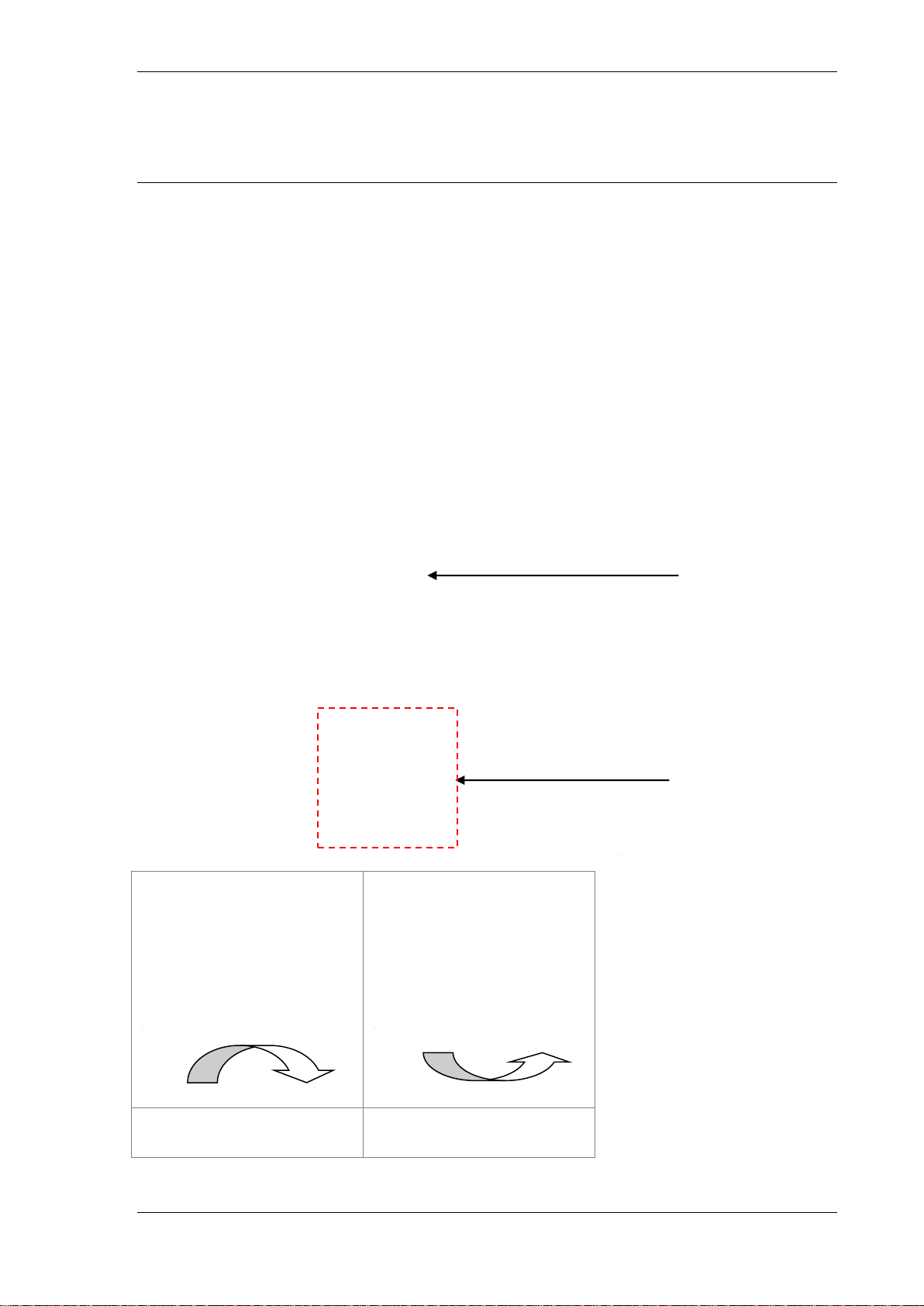
Moveable ‘arms’ attached to
front pair of feet
Positioning the Calibrator
The 1000 series calibrator is available in a variety of different casings for use on
site, on a bench or in a rack.
Care should be taken when positioning the calibrator to ensure that items are not
placed against the cooling vents. Placing items against the cooling vents will affect
the performance of the calibrator and reduce the amount of time that the 10A output
will operate for before reaching thermal cut-out conditions (see Page 70)
When considering placement of the 1000A (in ruggedized casing), ensure that the
calibrator is placed on a flat, stable surface.
For bench-top use, the 1000B (bench top casing) is fitted with 4 non-slip feet. The
front pair of feet are fitted with moveable ‘arms’ that can be positioned to raise the
front of the calibrator to a more ergonomic position.
TRANSMILLE LTD. Version 1.30 Page 9

1000 SERIES OPERATION MANUAL
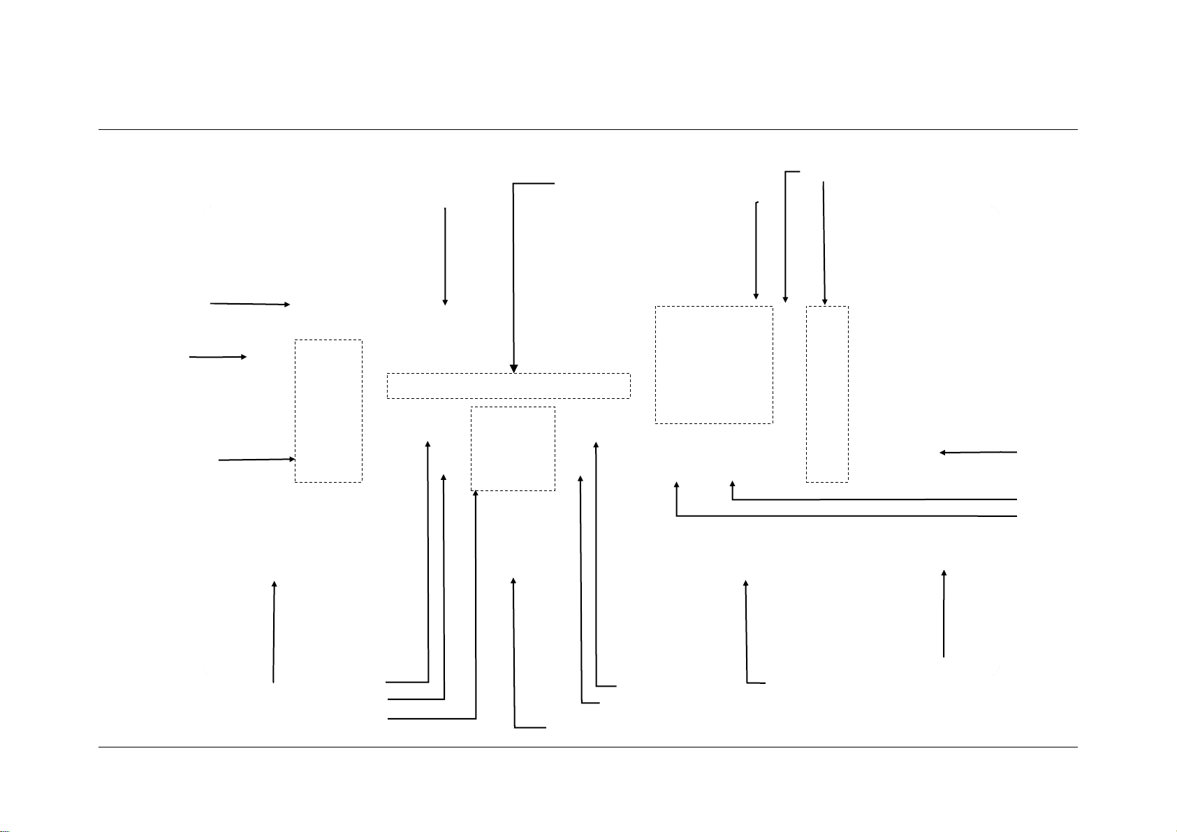
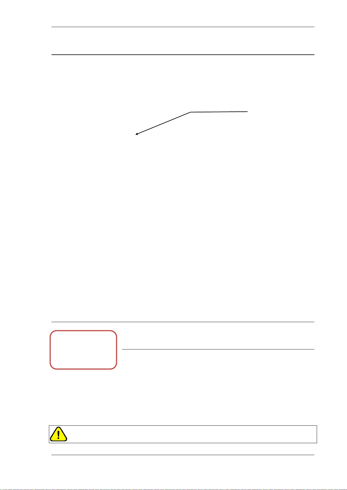
Adapter Interface
Mains / Line Inlet
(IEC) Connector
Fuse Holder
USB Interface
Connector
Power
Switch
Line Power / Fuse Ratings
Cooling Vents
Power and Interface Connections
Connections on the front panel are for Line Power via a 3 Pin IEC connector
incorporating the Line fuse and on-off switch, and a Female Type B USB connector
for interfacing with a computer.
The 1000 Series is provided with an IEC lead suitable for the country of shipping, if
a different lead is required please inform Transmille prior to shipping.
TRANSMILLE LTD. Version 1.30 Page 10
1000 SERIES OPERATION MANUAL
Checking the Line Voltage
Warning: The line power cord must have an earth
conductor to avoid risk of shock.
This instrument must be correctly earthed.
The calibrator must be ordered with 100-120 Volt line supply or 220 - 240 Volt line
supply option. Check that the line voltage matches the configured voltage before
connecting the power to the instrument. The input voltage is indicated on the front
panel underneath the power switch.
Warning: Connecting the calibrator to the wrong supply will
cause internal damage to the instrument.
Power Line Inlet Fuse and rating
The power line inlet fuse is located directly below the power inlet within the voltage
selector housing. The correct fuse rating is 2A anti-surge (slow blow) for 230V
operation and 4A anti-surge (slow blow) for 110V operation.
Replacing the Power Line Fuse
In the event of the Power Line fuse being damaged, the fuse will need to be
replaced. This operation can be performed by the user.
TRANSMILLE LTD. Version 1.30 Page 11

1000 SERIES OPERATION MANUAL
Warning: Ensure Line Power has been disconnected from
the instrument before performing this procedure
Using a Flat Head screwdriver, insert the end of the screw driver into the recess on
the fuse holder. The screwdriver must be parallel to the front panel of the calibrator
Once the screwdriver is in the recess of the fuse holder, gently hinge the fuse holder
up (away from the front panel). Be careful not to damage the fuse holder by applying
too much force. The fuse holder will lift out, revealing the fuse. Check the fuse using
a continuity tester to ensure that the problem is the fuse. If the fuse is damaged,
replace the fuse with an anti-surge fuse of the recommended rating for the supply
voltage. Re-insert the fuse holder in the same orientation as it was removed.
TRANSMILLE LTD. Version 1.30 Page 12

1000 SERIES OPERATION MANUAL
Connecting to a computer
A USB cable (supplied) should be used to connect the calibrator to a USB port
on a computer.
Connection Details
Connection from calibrator to a computer :
The USB connection on the 1000 series calibrator is a Female type B connection.
Also supplied is a USB driver on CD :
For details on installing USB driver see appendix A.
TRANSMILLE LTD. Version 1.30 Page 13

1000 SERIES OPERATION MANUAL
Powering up the calibrator
After connecting line power, the calibrator can be switched on with the line power
switch above the mains inlet socket on the front panel.
The fan will start and the front panel display will illuminate indicating power. The
display will show a firmware version number and after a short delay, during which
time the processor performs a self-test of the instrument, the display will show an
output of 0.0000mV DC. The default start condition of the calibrator is as follows:
Output Status : Standby
Range : 100mV DC
Negative to Ground Enabled
Allow the calibrator to warm up for 20 minutes to obtain full accuracy; the fast start
feature of the calibrator will give approximately 90% of full specifications within 10
minutes. The calibrator has been designed to be powered up continuously and does
not need to be turned off when not in use.
If required, a control program (i.e. ProCal) can now be started on the computer; the
program will establish communication with the calibrator. If used with ProCal, the
stored value of the passive standards will be downloaded to the computer, and the
calibrator will indicate ‘ProCal Control’ on the screen when ProCal is started.
TRANSMILLE LTD. Version 1.30 Page 14

1000 SERIES OPERATION MANUAL
Output Connections
Warning: Risk of shock.
High voltages may be present on the output sockets.
Output sockets are 4mm safety type, the voltage pair contacts are low thermal gold
plated for minimum thermal EMF.
The 1000 series calibrator’s outputs have been designed to allow most multimeters
to be calibrated without changing connections. There are 4 sets of outputs:
1) Voltage, Resistance, Capacitance, Frequency.
2) Current to 1A.
3) High 10A Current.
4) Thermocouple Output
The Voltage and Current terminals share a single common terminal. This allows the
1000 series to connect directly to all inputs on typical multimeters without the need
for changing leads as below:
When an output terminal pair is not active they are completely open circuit and
isolated from the other outputs.
Note: When outputting resistance, capacitance and frequency the calibrator will use
the voltage output terminals.
TRANSMILLE LTD. Version 1.30 Page 15
1000 SERIES OPERATION MANUAL
It is recommended that the voltage and low current leads be high quality screened
cable with gold plated 4mm plugs fitted. The cable must be able to withstand 1025
volts AC and have an insulation resistance greater than 1T to avoid introducing
any shunting effect on the high resistance ranges.
Poor quality test leads will introduce noise, thermal emf and leakage errors on low
voltage & current ranges and also unstable readings on resistance and capacitance
outputs (see measurement techniques). Special test leads are available from
Transmille for ensuring accurate measurements, see accessories.
Warning: Under no circumstances should any voltage
be connected to the calibrator outputs*. The 1000 Series
calibrator outputs are protected with IGuard however we
advise to be vigilant against accidental connections
* Insulation testers up to 1000V may be connected when using the Insulation test functions
Output Overloads
If the calibrator is unable to drive the load then the output will be turned off and the
calibrator returned to standby mode. The message Standby will be displayed on
the front panel. The output will be automatically reset on setting the output again.
TRANSMILLE LTD. Version 1.30 Page 16

1000 SERIES OPERATION MANUAL
Operation
Safety Warnings
WARNING: The information in this section is intended only
for qualified personnel. The user must at all times be
adequately protected from electric shock. Qualified
personnel must ensure that operators of the equipment are
adequately insulated from connection points.
WARNING: This instrument is capable of generating both
DC and AC high voltages.
Introduction to Operation
All functions of the 1000 Series Calibrator can be controlled from the front panel, or
controlled remotely by a computer over the interface.
The front panel controls are ‘locked out’ when controlled by a computer, but local
control may be resumed by selecting the ‘local’ soft key - it must be remembered
that this action may disrupt the computer program.
TRANSMILLE LTD. Version 1.30 Page 17
LCD Display with
integral Backlight
Menu buttons
(Soft Keys)
Active
Terminal
Indication
LEDs
Safety Output
Terminals
Output On Button
Standby Button
Numeric Keypad
Multiplier Keys
Function Keys
Digital Control
Adapter Interface
Range Up / X 10 Key
Range Up / ÷ 10 Key
Ref Key and
Directional Arrows
Instrument Serial
Number
Calibration Label
Thermocouple
Output
USB Interface
Enter Key
Shift Key
Front Panel Controls and Indicators
TRANSMILLE LTD. Version 1.30 Page 18

Output Value &
Range
Dynamic
Soft key Menu
Low to Ground
Output On / Standby
Indicators
Deviation (ppm)
Function Specific
Configuration
Display
Graphic LCD Display
The graphic backlit LCD display shows the present output, instrument status, % or
ppm change from the entered value, and also the new value being entered. The
bottom portion of the display is used to assign the function of the four ‘soft keys’.
TRANSMILLE LTD. Version 1.30 Page 19

1000 SERIES OPERATION MANUAL
Front Panel Keyboard
The front panel of the 1000 Series Calibrator utilises a high quality custom rubber
keyboard with tactile feel buttons and integral display window. The front panel is
therefore sealed against the ingress of moisture and dirt enabling the calibrator to be
used in most working environments without risk of early failure of the operating
buttons. The front panel can easily be wiped clean with a soft cloth. Care should be
taken not scratch the display window. All graphics are ‘under printed’ making them
rugged and durable.
IMPORTANT NOTE
The front panel key buttons are for use with fingers only - do not press
the key with hard or sharp objects e.g. Ball-point pens, pencils,
screwdrivers etc. Repeated actions like this will almost certainly cause
the keyboard to fail. (This will not be covered under warranty). Care
should also be taken when transporting the instrument, do not place
test leads or other objects on top of the panel which may come into
contact with the display area and cause damage.
TRANSMILLE LTD. Version 1.30 Page 20

1000 SERIES OPERATION MANUAL
Numeric section
Allows numeric values to be entered, also contains the + / - key
for entering polarity for DC settings, the Back space and Clear
key for information entry, the Shift key for selecting additional
functions and the Enter key for confirming data entry
Multiplier section
Mega (M), kilo (k), milli (m), micro(u) or nano (n)
Function section
Volts (V), Amps(A), Ohms,
Farads(F), Celsius(C), & Frequency(Hz)
Range Up / Range Down
Allow the output to be multiplied / divided by 10.
Left / Right / Up / Down Cursor Keys
To select the digit to be controlled by the rotary control.
Output On / Standby keys
Allow the calibrators output to be disconnected from the
terminals. LED indicators are incorporated in these switches to
clearly show the output status.
The Keyboard is divided into sections to allow easy operation.
TRANSMILLE LTD. Version 1.30 Page 21
1000 SERIES OPERATION MANUAL
Clockwise Rotation
(Increment Digit)
Anti-Clockwise Rotation
(Decrement Digit)
Cursor indicates the
highlighted digit
Cursor Keys can be
used to move the
position of the digit
marker, and increment /
decrement the digit.
Digital Control and Cursor Keys
A digital potentiometer allows the ‘highlighted digit’ on the display to be incremented
(turning clockwise) or decrement (turning anti-clockwise). As an output is changed,
the deviation from the original value entered on the keyboard is shown in either % or
ppm depending upon the magnitude of the change.
To ‘Reset’ the deviation calculation, press the REF key in the middle of the cursor
keys, this resets the reference value from which the deviation is calculated
TRANSMILLE LTD. Version 1.30 Page 22
1000 SERIES OPERATION MANUAL
Active terminals
indicated by
illuminated LED
Terminal status LED’s
LED’s above the terminals indicate which pair is active. When terminals are not
active they are electrically isolated from each other
All 4mm safety sockets share a single common terminal.
Voltage Output Terminal Pair (Black & White)
Low thermal 4mm safety terminals
Used for all voltage outputs up to 1025V, for resistance,
capacitance and frequency.
Also used for Insulation resistance, test voltage measurement
and continuity current measurement
WARNING: Dangerous voltage may be present on these terminals.
TRANSMILLE LTD. Version 1.30 Page 23

1000 SERIES OPERATION MANUAL
Low Current Output Terminal Pair (Black & Blue)
4mm safety terminals
Used for current outputs up to 1 Amp
High Curent Output Terminals (Black and Yellow)
4mm Safety terminals
Used for all currents above 1 Amp.
Thermocouple Output Terminals (White)
Mini thermocouple socket used for generation of
thermocouple output. Ensure the correct thermocouple
wiring is used to match the type (i.e. Type K, Type J)
TRANSMILLE LTD. Version 1.30 Page 24

1000 SERIES OPERATION MANUAL
9 Pin Adapter Interface Connector.
To expand the 1000 Series calibrators, an adapter interface is provided on the front
panel. This allows for connection to external adapters used for extending calibration
capability, e.g. Pressure measurement etc.
Incorporates a yellow LED to indicate when the adapter interface is active.
The pins connections are as follows:
Pin 1 – +15V
Pin 2 – Digital ground
Pin 3 – Strobe
Pin 4 – Data
Pin 5 – Select
Pin 6 – -15V
Pin 7 – Analogue ground
Pin 8 – Output
Pin 9 – Input
TRANSMILLE LTD. Version 1.30 Page 25

1000 SERIES OPERATION MANUAL
Key Name
Function
+ / -
In DC functions, pressing this key will
invert the polarity, e.g. an existing
setting of +1 V, pressing this key will
change the output to -1V
FREQ
Pressing this key will enter the
frequency output function, further
described
THERMO
Pressing this key will enter the
Thermocouple source function,
operation described
Key Name
Function
PRT
Pressing this key will enter the
simulated PRT output function,
operation described
PROCEDURE
Pressing this key will enter the
procedure select screen, further
described
INS TEST
Pressing this key will enter the
Insulation resistance function,
operation described
Soft Key Menus
Menu Structure
To access advanced functions of the calibrator, the 4 soft keys below the screen can
be used to select the menu functions that appear at the bottom of the screen.
There are 3 pages of menus, each featuring 3 separate functions and a next key.
TRANSMILLE LTD. Version 1.30 Page 26

1000 SERIES OPERATION MANUAL
Key Name
Function
CALIBRATE
Pressing this key will enter the
Calibration function, further described
SETUP
Pressing this key will enter the setup
menu, further described
INFO
Pressing this key will display the info
screen, further described
Procedure Menu
The 1000 series calibrators has the ability to store procedures in memory for on site
use. After pressing the ‘PROCEDURE’ key the calibrator will display a list of
procedures that have been loaded.
Using the arrows keys (as described on page 22), move the cursor to the desired
model number and press the ‘SELECT’ soft key
TRANSMILLE LTD. Version 1.30 Page 27

1000 SERIES OPERATION MANUAL
Function Name
Description
Beeper
This menu item allows the beeper to be
turned on or off. With the beeper off the
unit will not emit any noises for key
presses, however beeps will STILL be
emitted for HV ramps and errors.
Password
This function prompts the user to enter
the calibration password. After entering
the correct password the calibrator will
be in calibration mode.
Another function of this key, once
already in calibration mode, is to edit the
system password to a new password.
Adapters
This menu item allows the user to edit
the displayed unit for pressure adapters
that have been stored in the calibrator
Range Hold
This function enables a ‘Range Hold’
function on the calibrator, enabling
outputs that would not normally be
available from the range to be output, i.e.
50mV from the 1V range
Setup Menu
To configure the 1000 series calibrator, a setup menu is provided. This allows users
to configure options, i.e. the Calibration Password.
Using the arrows keys (as described on page 22), move the cursor to the desired
function and press the ‘Select’ soft key or press the enter button.
TRANSMILLE LTD. Version 1.30 Page 28

1000 SERIES OPERATION MANUAL
Connection Diagrams
Provided in this section are example connection diagrams for typical pieces of test
equipment, indicating the terminals to use
DC / AC Voltage
DC / AC Current – Outputs below 1A
TRANSMILLE LTD. Version 1.30 Page 29

1000 SERIES OPERATION MANUAL
DC/AC Current – Outputs above 1A
Resistance
TRANSMILLE LTD. Version 1.30 Page 30
 Loading...