

User’s Guide
SIBTF10xx-1xx-MR & SIBTF10xx-1xx-MS
Substation-Rated Industrial Ethernet Switch
• 10/100Base-TX to 100Base-FX
• Single or Redundant Wide Input Power
Supply
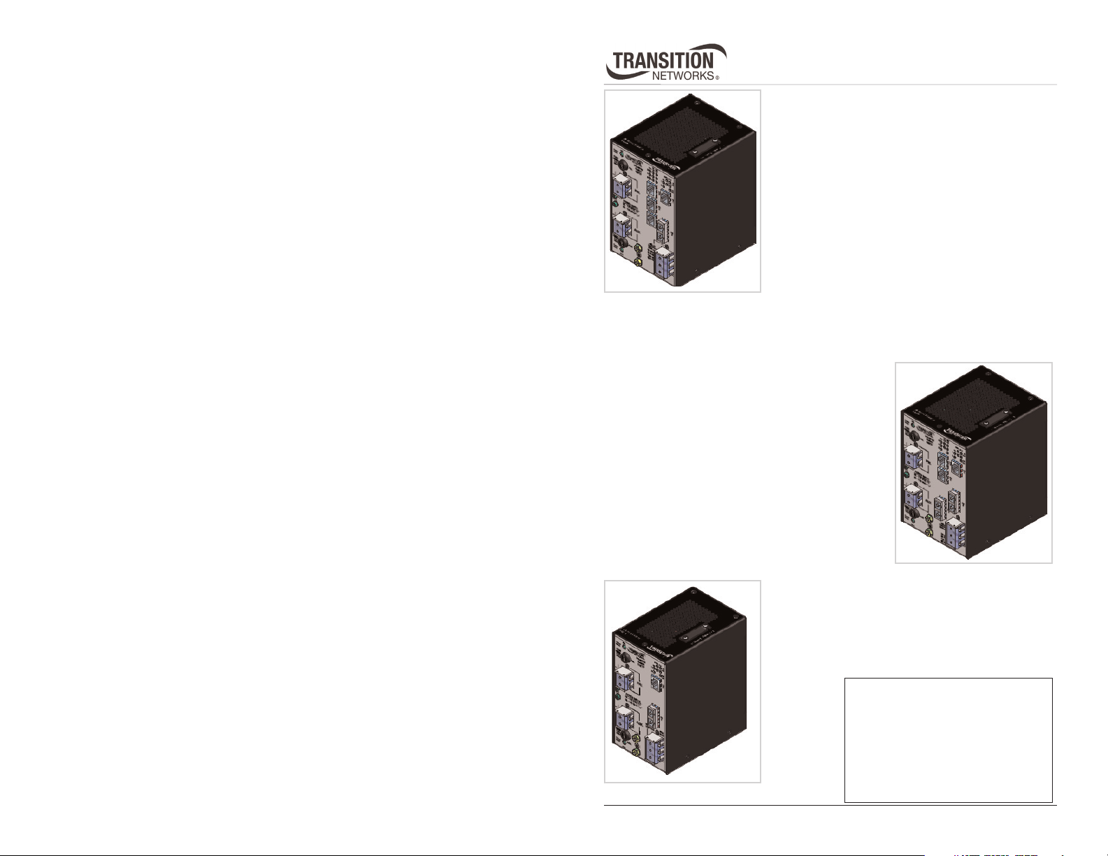
The SIBTF10xx-1xx-Mx Ethernet industrial switches
allow connecting 10Base-T Ethernet/100Base-TX fast
Ethernet twisted-pair copper network devices to
network devices on a 100Base-FX fast Ethernet fiber
140-MR
and one fiber port. The SIBTF10xx-140-MR model includes redundant power-supply
terminal blocks that can handle 48–170VDC or 90–125VAC, 50/60Hz input power. The
SIBTF10xx-140-MS model, not shown, has a single power-supply terminal block (TB).
The SIBTF10xx-130-MR has three RJ-45 copper ports
and two fiber ports. The SIBTF10xx-130-MR model
includes redundant power-supply terminal blocks that
can handle 48–170VDC or 90–125VAC, 50/60Hz
input power. The SIBTF10xx-130-MS model, not
shown, has a single power-supply terminal block (TB).
network.
The SIBTF10xx-140-MR has four RJ-45 copper ports
110-MR
130-MR
The SIBTF10xx-110-MR has one RJ-45 copper port
and one fiber port. The SIBTF10xx-110-MR model
includes redundant power-supply terminal blocks that
can handle 48–170VDC or 90–125VAC, 50/60Hz
input power. The SIBTF10xx-110-MS model, not
shown, has a single power-supply terminal block (TB).
Available Models . . . . . . . . . . . . .2
Installation . . . . . . . . . . . . . . . . . .4
Operation . . . . . . . . . . . . . . . . . .15
Cable Specifications . . . . . . . . . .20
Technical Specifications . . . . . . .22
Troubleshooting . . . . . . . . . . . . .24
Contact Us . . . . . . . . . . . . . . . . .26
Compliance Information . . . . . . .27
SIBTF10xx-1xx-Mx
Available Models
Available SIBTF10xx-140-MR and MS models*
Part Number (4) Copper - 10Base-T/
100Base-TX ports
SIBTF1011-140-Mx
SIBTF1013-140-Mx
SIBTF1014-140-Mx
SIBTF1015-140-Mx
SIBTF1016-140-Mx
SIBTF1017-140-Mx
RJ-45
100 m (328 ft)
RJ-45
100 m (328 ft)
RJ-45
100 m (328 ft)
RJ-45
100 m (328 ft)
RJ-45
100 m (328 ft)
RJ-45
100 m (328 ft)
*MR = Redundant power-supply terminal blocks, MS = Single power-supply terminal block.
Note: The cable distances listed are maximum distances typically. The actual distance
is dependent upon the physical characteristics of the network.
Available SIBTF10xx-130-MR and MS models*
Part Number (3) Copper - 10Base-T/
SIBTF1011-130-Mx
SIBTF1013-130-Mx
SIBTF1014-130-Mx
SIBTF1015-130-Mx
SIBTF1016-130-Mx
SIBTF1017-130-Mx
100Base-TX Ports
RJ-45
100 m (328 ft)
RJ-45
100 m (328 ft)
RJ-45
100 m (328 ft)
RJ-45
100 m (328 ft)
RJ-45
100 m (328 ft)
RJ-45
100 m (328 ft)
(1) Duplex Fiber-Optic - 100Base-FX port
ST, 1300 nm multimode, duplex
2 km (1.2 miles)
SC, 1300 nm multimode, duplex
2 km (1.2 miles)
SC, 1310 nm single mode, duplex
20 km (12.4 miles)
SC, 1310 nm single mode, duplex
40 km (24.8 miles)
SC, 1310 nm single mode, duplex
60 km (37.2 miles)
SC, 1550 nm single mode, duplex
80 km (49.7 miles)
(2) Duplex Fiber-Optic - 100Base-FX
Ports
ST, 1300 nm multimode, duplex
2 km (1.2 miles)
SC, 1300 nm multimode, duplex
2 km (1.2 miles)
SC, 1310 nm single mode, duplex
20 km (12.4 miles)
SC, 1310 nm single mode, duplex
40 km (24.8 miles)
SC, 1310 nm single mode, duplex
60 km (37.2 miles)
SC, 1550 nm single mode, duplex
80 km (49.7 miles)
Available Models -- continued
Available SIBTF10xx-110-MR and MS models*
Part Number (1) Copper - 10Base-T/
100Base-TX Port
SIBTF1011-110-Mx
SIBTF1013-110-Mx
SIBTF1014-110-Mx
SIBTF1015-110-Mx
SIBTF1016-110-Mx
SIBTF1017-110-Mx
RJ-45
100 m (328 ft)
RJ-45
100 m (328 ft)
RJ-45
100 m (328 ft)
RJ-45
100 m (328 ft)
RJ-45
100 m (328 ft)
RJ-45
100 m (328 ft)
*MR = Redundant power-supply terminal blocks, MS = Single power-supply terminal block..
Note: The cable distances listed are maximum distances typically. The actual distance
is dependent upon the physical characteristics of the network.
(1) Duplex Fiber-Optic - 100Base-FX Port
ST, 1300 nm multimode, duplex
2 km (1.2 miles)
SC, 1300 nm multimode, duplex
2 km (1.2 miles)
SC, 1310 nm single mode, duplex
20 km (12.4 miles)
SC, 1310 nm single mode, duplex
40 km (24.8 miles)
SC, 1310 nm single mode, duplex
60 km (37.2 miles)
SC, 1550 nm single mode, duplex
80 km (49.7 miles)
*MR = Redundant power-supply terminal blocks, MS = Single power-supply terminal block.
Note: The cable distances listed are maximum distances typically. The actual distance
is dependent upon the physical characteristics of the network.
2
24-Hour Technical Support: 1-800-260-1312 International: 00-1-952-941-7600
techsupport@transition.com -- Click the “Transition Now” link for a live Web chat.
3
SIBTF10xx-1xx-Mx
Installation
Features
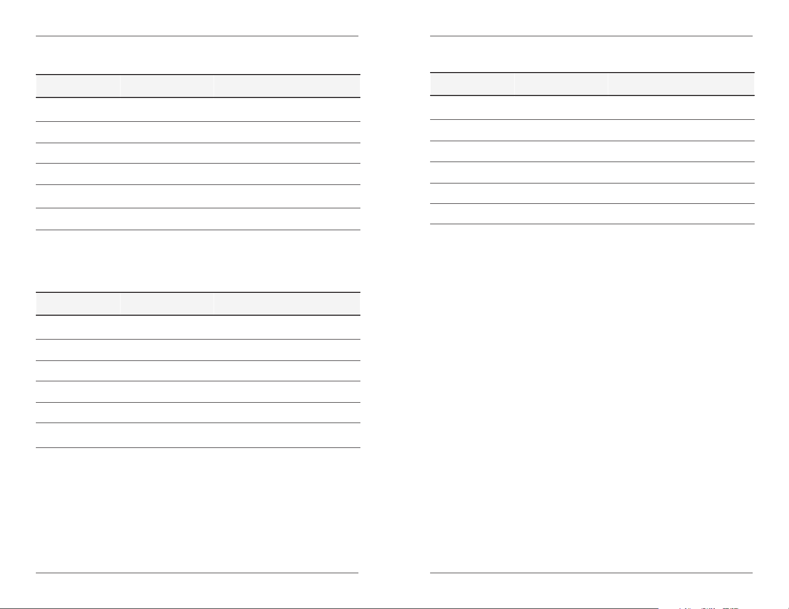
• The SIBTF10xx-140-MR industrial switch includes four (4) RJ-45, twisted-pair
copper ports and one (1) 100 Mb fiber optic port.
• The Auto-Negotiation feature on port “1” can be turned OFF and forced to a
selected speed (100 Mb/s or 10 Mb/s) also duplex mode (full or half).
• All SIBTF models include a primary input terminal block (TB) for 48–170VDC or
90–125VAC power, a 2.5A, 250V fuse, an LED power indicator, and a red-fault
LED. The red-fault LED “ON state” indicates the microcontroller did not initialize
correctly.
• The “MR” models include an auxiliary power-supply terminal block—not available
on “MS” models.
See Figure 1.
Installation -- continued
Features -- continued
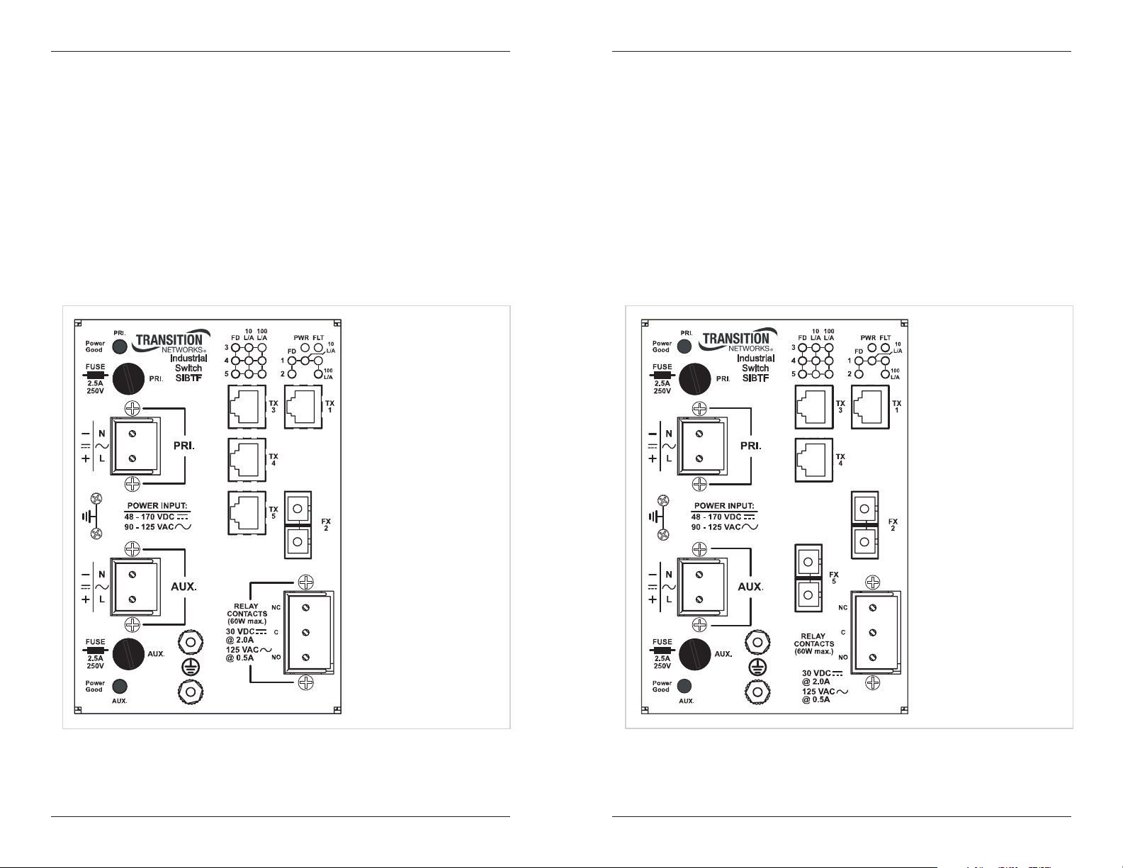
• The SIBTF10xx-130-MS industrial switch includes three (3) RJ-45, twisted-pair
copper ports and one (2) 100 Mb fiber optic port.
• The Auto-Negotiation feature on port “1” can be turned OFF and forced to a
selected speed (100 Mb/s or 10 Mb/s) and duplex mode (full or half).
• All SIBTF models include a primary input terminal block (TB) for 48–170VDC or
90–125VAC input power power, a 2.5A, 250V fuse, an LED power indicator, and a
red-fault LED. The red-fault LED “ON state” indicates the microcontroller did not
initialize correctly.
• The “MR” models include an auxiliary power-supply terminal block—not available
on “MS” models.
See Figure 2.
Figure 1: SIBTF10xx-140-MR Front Panel
4
24-Hour Technical Support: 1-800-260-1312 International: 00-1-952-941-7600
Figure 2: SIBTF10xx-130-MR Front Panel
techsupport@transition.com -- Click the “Transition Now” link for a live Web chat.
5
SIBTF10xx-1xx-Mx
Installation -- continued
Features -- continued
• The SIBTF10xx-110-MS industrial switch includes one (1) RJ-45, twisted-pair
copper port and one (1) 100 Mb fiber optic port.
• The Auto-Negotiation feature on port “1” can be turned OFF and forced to a
selected speed (100 Mb/s or 10 Mb/s) and duplex mode (full or half).
• All SIBTF models include a primary input terminal block (TB) for 48–170VDC or
90–125VAC power, a 2.5A, 250V fuse, an LED power indicator, and a fault LED.
The red-fault LED “ON state” indicates the microcontroller did not initialize
correctly.
• The “MR” models include an auxiliary power-supply terminal block—not available
on “MS” models.
See Figure 3.
Installation -- continued
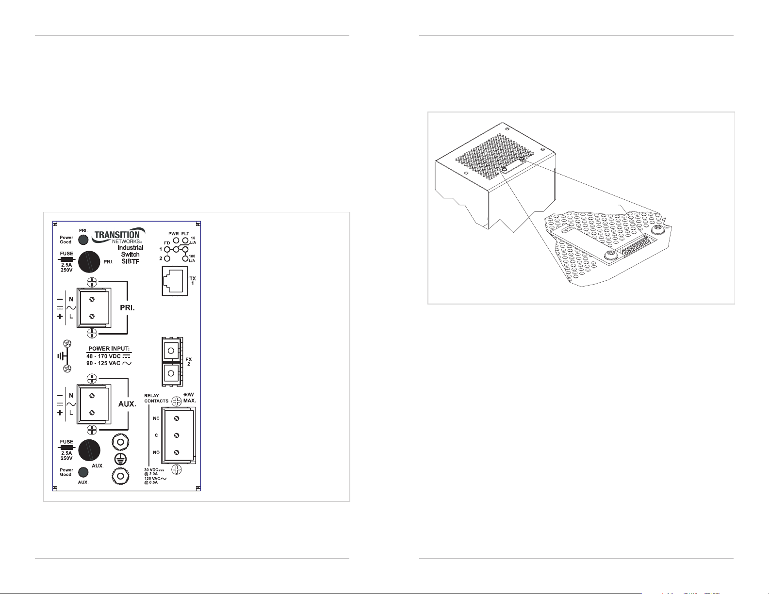
Enclosure top view (configuration switches)
The SIBTF10xx-1xx-Mx has eight (8) configuration (DIP) switches located under the
switch cover on top of the enclosure. See Figure 4.
Switch Position 1
1-Config Switches
Figure 4: Enclosure Top View Configuration Switches
Figure 3: SIBTF10xx-110-MR Front Panel
6
24-Hour Technical Support: 1-800-260-1312 International: 00-1-952-941-7600
Setting configuration switches
To set the DIP switches:
1. Using a small, phillips-head screwdriver, loosen (do not remove) the two screws
that secure the cover to the switch.
2. Swing the switch cover counter-clockwise to expose the DIP switches.
3. Use a small, flathead screwdriver to set the recessed switches as required by the
network application.*
4. Slide the switch cover back over the DIP switches and then secure it by
tightening both screws.
*Note: Switches 1, 2, and 3 apply only to twisted-pair “copper port #1.”
techsupport@transition.com -- Click the “Transition Now” link for a live Web chat.
7

SIBTF10xx-1xx-Mx
g
Installation -- continued
DIP switch settings
1. Port 1 copper Auto-Negotiation:
UP (Enabled) - Advertises switch speed and mode
capabilities to the network:
• 100Mb/s full-duplex • 100Mb/s half-duplex,
• 10Mb/s full-duplex • 10Mb/s half-duplex.
DOWN (Disabled) - Does not advertise switch speed
and mode capabilities to the network. With AutoNegotiate disabled switches 2 and 3 are used to set the
twisted-pair speed and mode.
2. Port 1 copper speed:
UP (100Base-TX) - Sets the twisted-pair speed to
100Base-TX.
DOWN (10Base-T) - Sets the twisted-pair speed to
10Base-T.
3. Port 1 copper duplex:
UP (Full-Duplex) - The twisted-pair cable distances
are constrained by the cable requirements.
DOWN (Half-Duplex): - The twisted-pair cable
distances are constrained by the 512-Bit Rule.
4. Fiber port FX 1 duplex:
UP (Full-Duplex) - The cable distances for the fiber
port are constrained by the cable requirements.
DOWN (Half-Duplex) - The cable distances for the
fiber port are constrained by the 512-Bit Rule.
1
Auto-Negotiation E nabled
Auto-Ne
otiation Dis abled
2
100Bas e-TX
10Bas e-TX
3
Full Duplex
Half Duplex
4
Full Duplex (fiber)
Half Duplex (fiber)
Installation -- continued
6. Link Pass-Through (model 110 only):
UP (Enable) - When Link Pass-Through is enabled, a fault
on one side of the switch stops the signal and data
transmission on the other side. See the detailed explanation
of Link Pass-Through on page 18.
DOWN (Disable) - When Link Pass-Through is disabled, a
fault on one side of the switch does not stop the signal and
data transmission on the other side.
7. Fiber redundancy (model 130 only):
UP (Disable) - When fiber redundancy is disabled, the
two fiber ports (1 and 2) act as normal bridging ports.
DOWN (Enable) - When fiber redundancy is enabled,
the two fiber ports (1 and 2) are configured as
forwarding or disabled. At any given time one port will
be disabled and one port will be forwarding.
8. AutoCross:
UP (Enable) - The switch will connect to a straightthrough or a crossover twisted-pair copper cable
automatically.
DOWN (Disable) - In the down position the straightthrough or crossover twisted-pair copper cable must be
installed according to the site requirements.
6
Link Pa ss- Through E nabled
Link Pa ss- Through Disabled
7
Redund ant Fiber E nabled
Redund ant Fiber Disabled
8
AutoCross E nabled
AutoCross Disab led
5. Fiber port FX 2 duplex (model 130 only):
UP (Full-Duplex) - The cable distances for the fiber
port are constrained by the cable requirements.
DOWN (Half-Duplex) - The cable distances for the
fiber port are constrained by the 512-Bit Rule.
8
24-Hour Technical Support: 1-800-260-1312 International: 00-1-952-941-7600
Full Duplex (fiber)
Half Duplex (fiber)
5
techsupport@transition.com -- Click the “Transition Now” link for a live Web chat.
9

SIBTF10xx-1xx-Mx
Installation -- continued
WARNING: Make sure that the external power source is turned OFF before
attempting to connect power leads to the industrial switch. Failure to observe
this warning could result in an electrical shock.
WARNING: The SIBTF10xx-1xx-Mx is a class I device. It has a provision
for protective earth grounding. Equipment grounding is vital to ensure safe
operation. The SIBTF switch must be earth grounded during and after
installation. Failure to observe this warning could result in an electric shock.
Note: DO NOT use bare (exposed) or un-lugged power-source wires to connect to the
industrial switch.
Connecting primary power
The industrial switch is designed to accommodate 48 – 170VDC or 90 – 125VAC,
50/60 Hz input power via its primary terminal block (TB).
To provide power to the industrial switch via the primary TB, view Figure 5, and then
do the following:
1. Verify that the external power source is turned OFF and disconnect.
2. Loosen the grounding screw and then connect the power source functional-ground
lead to the grown screw, as shown in Figure 5. Tighten the screw to secure.
3. Loosen the TB screw marked “-” and then connect the power source neutral or (-)
negative lead to the TB negative terminal, as shown in Figure 5. Tighten the
screw to secure.
4. Loosen the TB screw marked “+” and then connect the power source line phase or
positive (+) lead to the TB positive terminal, as shown in Figure 5. Tighten the
screw to secure.
5. Re-connect and turn ON the external power source.
6. Verify that the industrial switch has powered up by observing the illuminated
“Power Good” LED on the front panel.
Installation -- continued
WARNING: Make sure that the external power source is turned OFF before
attempting to connect power leads to the industrial switch. Failure to observe
this warning could result in an electrical shock.
WARNING: The SIBTF10xx-1xx-Mx is a class I device. It has a provision
for protective earth grounding. Equipment grounding is vital to ensure safe
operation. The SIBTF switch must be earth grounded during and after
installation. Failure to observe this warning could result in an electric shock.
Note: DO NOT use bare (exposed) or un-lugged power-source wires to connect to the
SIBTF10xx-10x-MR industrial switch.
Connecting auxiliary power
The SIBTF10xx-10x-MR switches support a redundant power supply. If the primary
power source fails, the auxiliary power source supplies power to the industrial switch.
To provide auxiliary power to the industrial switch, view Figure 6 and do the
following:
1. Verify that the external power source is turned OFF and disconnected.
2. Loosen the grounding screw and connect the power source functional-ground lead
to the grown screw, as shown in Figure 6. Tighten the screw to secure.
3. Loosen the TB screw marked “-” and then connect the power source neutral or (-)
negative lead to the TB negative terminal, as shown in Figure 6. Tighten the
screw to secure.
4. Loosen the TB screw marked “+” and then connect the power source line phase or
positive (+) lead to the TB positive terminal, as shown in Figure 6. Tighten the
screw to secure.
5. Re-connect and turn ON the external power source.
6. Verify that the industrial switch is powered UP: auxiliary “Power Good” LED on
the lower front panel will be ON.
N
L
POWER I NPUT
48 - 170 VDC
90 - 125 VAC
PRI.
Figure 5: Primary Power Connection
10
24-Hour Technical Support: 1-800-260-1312 International: 00-1-952-941-7600
AUX.
Figure 6: Auxiliary Power Connection
techsupport@transition.com -- Click the “Transition Now” link for a live Web chat.
11

SIBTF10xx-1xx-Mx
Installation -- continued
Internal relay connections
The internal relay can activate an external fault indicator. The fault indicator connects
to the relay contacts on the front panel. An example would be a fault circuit connected
to a warning light located in a control room. The light can be connected in a normally
open (NO) or normally closed (NC) configuration with respect to circuit common (C)
to turn the light ON/OFF when a fault occurs.
To connect a fault indicator to the relay, view Figure 7 and then do the following:
1. Verify that the external power source is turned OFF.
2. Loosen the relay’s “NO” screw and then connect the fault indicator’s return lead
to terminal “NO.” Tighten the screw to secure.
3. Loosen the relay’s “C” screw and then connect the fault indicator’s common lead
terminal “C.” Tighten the screw to secure.
Or:
4. Loosen the relay’s “NC” screw and then connect the fault indicator’s return lead
to terminal “NC.” Tighten the screw to secure.
5. Loosen the relay’s “C” screw and then connect the fault indicator’s common lead
terminal “C.” Tighten the screw to secure.
Relay
Contacts
(600W max.)
30 VDC
@2.0A
125 VAC
@0.5A
NC
C
NO
NC
C
NO
Installation -- continued
DIN-Rail
The industrial switch includes an aluminum DIN-Rail mounting bracket attached to the
back panel of the enclosure. See Figure 8.
Back View
DIN Rail
Mounting Bracket
Figure 8: DIN-Rail Bracket
Mounting the enclosure to a DIN-Rail
CAUTION: The SIBTF10xx-1xx switch is convection cooled, requiring
unrestricted bottom-to-top airflow. Mounting the device in other
orientations could result in unreliable operation or device failure.
CAUTION: To prevent debris from falling through the ventilation holes,
local and national electrical and fire codes might require orienting the device
with its small-diameter vent holes downward.
Figure 7: Internal Relay Connections
Two wiring scenarios:
• Wiring the relay in the normally closed (NC) configuration can be used to
monitor alarm indicators connected in series, where any single event will cause all
alarm indicators to trigger.
• Wiring the relay in the normally open (NO) configuration can be used to monitor
alarm indicators connected in parallel, where any single event will cause that
events alarm indicator to trigger: i.e., a light turning ON or OFF.
CAUTION: Calculate the maximum possible current in each power wire
and relay-contact wire. Observe all electrical codes for maximum current
allowed. If the current goes above the maximum ratings, the wiring could
overheat and cause serious damage to the network wiring or equipment.
12
24-Hour Technical Support: 1-800-260-1312 International: 00-1-952-941-7600
To mount the enclosure onto a DIN-Rail:
1. Insert the top of the DIN-Rail into the upper slot of the mounting plate.
2. Push down and then rotate the industrial switch inward to snap it into place onto
the DIN-Rail.
An illustration of the procedure is shown in Figure 9.
Step 1 Step 2
Mounting Plate
DIN-Rail
Figure 9: Enclosure Mounted to DIN-Rail
techsupport@transition.com -- Click the “Transition Now” link for a live Web chat.
13

SIBTF10xx-1xx-Mx
Installation -- continued
Installing fiber cable
To install a fiber cable, view Figure 10, and then do the following:
1. Locate or build 100Base-FX fiber cable with male, two-stranded TX to RX
connectors installed at both ends.
2. Connect the fiber cables to the industrial switch as follows:
• Connect the male TX cable connector to the female TX port.
• Connect the male RX cable connector to the female RX port.
3. Connect the fiber cables to the other device (another media converter, hub, etc.)
as follows:
• Connect the male TX cable connector to the female RX port.
• Connect the male RX cable connector to the female TX port.
Connect fiber cable
to media converter
as shown.
RX
TX
Figure 10: Fiber Cable Installation
Installing copper cable
The AutoCross feature allows connecting straight-through (MDI) or crossover (MDIX) copper cable to the RJ-45 port of a second device.
To install an Ethernet cable, view Figure 11, and then do the following:
1. Locate or build 10Base-T or 100Base-TX copper cables with male, RJ-45
connectors installed on both ends.
2. Connect the RJ-45 connector at one end of the cable to the RJ-45 port on the
industrial switch.
3. Connect the RJ-45 connector at the other end of the cable to the RJ-45 port on the
second device (PLC, workstation, etc.).
Connect fiber cable
to other device
(media converter,
hub, etc.) as shown
RX
TX
Installation -- continued
Installing copper cable
R J-45 Po rts
industria l bridge
Figure 11: Copper Cable Installation
RJ-45 Port
P LC, wo rks tat ion, e tc.
Operation
Copper/fiber status LEDs
Copper LEDs
The SIBTF10xx-1xx-Mx comes equipped with status LEDs to monitor the network
connections for the copper and fiber ports.
The numbered LEDs refer to the numbered copper and fiber ports. For example, LED
#1 refers to the twisted-pair copper port #1; LED #2 refers to fiber port #2. See
Figure 12.
Each port has three associated LEDs: Full duplex (FD), 10MB, and 100MB.
Copper Port
Fiber Port
14
24-Hour Technical Support: 1-800-260-1312 International: 00-1-952-941-7600
Figure 12: Copper and Fiber Port Status LEDs
techsupport@transition.com -- Click the “Transition Now” link for a live Web chat.
15

SIBTF10xx-1xx-Mx
Operation -- continued
Copper/fiber status LEDs -- continued
Copper LEDs
The function of the copper port LEDs (1, 2, 3, and 4) are as follows:
100MB ON The copper port has established a link at 100 MB/s.
100MB Flashing The copper port is transmitting signals at 100 Mb/s.
10MB ON The copper port has established a link at 10 MB/s.
10MB Flashing The copper port is transmitting signals at 10 Mb/s.
FD ON The copper port is in full-duplex mode.
FD OFF The copper port is in half-duplex mode.
Fiber LEDs
The functions of the fiber port LEDs (2 and 5) are as follows:
100MB ON The fiber port has established a link.
100MB Flashing The fiber port is transmitting signals.
10MB -- N/A
10MB -- N/A.
FD ON The fiber port is in full-duplex mode.
FD OFF The fiber port is in half-duplex mode.
Fault (red) LED
Fault LED ON (red) indicates that the microcontroller did not initialize correctly; as a
result, the switch will not power up.
Fault LED
Operation -- continued
Product Features
Immunity standards
The industrial switch is designed to meet EN61000-6-2, IEEE1613.
Congestion reduction
The SIBTF10xx-1xx industrial switch does not forward collision signals or error
packets from one collision domain to another, which improves baseline-network
performance. In addition, the industrial switch filters packets destined for local
devices, which reduces network congestion.
Rate conversion
The SIBTF10xx-1xx industrial switch allows connecting 10Mb/s terminal devices on a
10Base-T legacy Ethernet copper network and/or 100Mb/s terminal devices on a
100Base-TX fast Ethernet copper network to 100Mb/s terminal devices on a 100Base
FX fast Ethernet fiber network.
Full-Duplex network
In a full-duplex network, maximum cable lengths are determined by the type of cables
used. See cable specifications section for the different SIBTF10xx-1xx models. The
512-Bit Rule does not apply in a full-duplex network.
Half-Duplex network (512-Bit Rule)
In a half-duplex network, the maximum cable lengths are determined by the round trip
delay limitations of each fast Ethernet collision domain. (A collision domain is the
longest path between any two terminal devices: e.g., a terminal, switch, or router.)
The 512-Bit Rule determines the maximum length of cable permitted by calculating
the round-trip delay in bit-times (BT) of a particular collision domain. If the result is
less than or equal to 512 BT, the path is good.
For more information on the 512-Bit Rule, see the white paper titled “Collision
Domains” on the Transition Networks website at: www.transition.com.
Copper Port
Figure 13: Fault LED
16
24-Hour Technical Support: 1-800-260-1312 International: 00-1-952-941-7600
Fiber Port
techsupport@transition.com -- Click the “Transition Now” link for a live Web chat.
17

SIBTF10xx-1xx-Mx
pp
pp
k
Operation -- continued
Product features -- continued
Auto-Negotiation
The Auto-Negotiation feature allows the SIBTF10xx-1xx industrial switch to
configure itself to achieve the best possible mode of operation over a link
automatically. The industrial switch broadcasts its speed (10 Mb/s or 100 Mb/s) and
duplex capabilities (full or half) to the other devices and negotiates the best mode of
operation. Auto-Negotiation allows quick and easy installation because the optimal
link is established automatically.
In a scenario where the industrial switch is linked to a non-negotiating device, the
admin person may want to disable Auto-Negotiation. In this instance, the mode of
operation will drop to the lowest common denominator between the two devices: 10
Mb/s, half-duplex. Disabling this feature provides the ability to force the connection
to the best mode of operation.
Link Pass-Through
The SIBTF10xx-110 industrial switch provides a Link Pass-Through feature, which
allows monitoring its fiber (FX) and copper (RX) (receive) ports for signal loss. Refer
to Figure 14, in the event of an RX signal loss (1), the industrial switch will
automatically disable the TX (transmit) signal (2) thus “passing through” the link loss
(3). The far-end device is automatically notified of the link loss (4), which prevents
date losses by transmitting data over an invalid link unknowingly.
media converter A
disables the fiber TX link
media converter B
loses the fiber RX link
Operation -- continued
AutoCross™
When the AutoCross feature is activated, it allows the use of straight-through MDI or
crossover MDI-X cables for connecting to 10Base-T or 100Base-TX devices.
AutoCross determines the characteristics of the connection and automatically
configures the unit to link up, regardless of the cable configuration, either MDI or
MDI-X.
Replacing the fuse
Note: The fuse may be “hot swapped” (i.e., replaced while the industrial switch is in
operation) provided the power source associated with the burned-out fuse has
been disconnected. For example, the primary fuse may be replaced provided
that power to the primary power contacts has been turned OFF.
To replace the fuse, view Figure 15, and then do the following:
1. Turn OFF and disconnect the power source associated with the blown fuse.
2. Using a flat-head screwdriver, unscrew (counter-clockwise) and remove the fuse
holder. See Figure 15.
3. Carefully remove the fuse from the fuse holder.
4. Install a same size and rated (2.5 A, 250 V) replacement fuse in the fuse holder.
5. Insert the fuse holder with the fuse into the switch and rotate clockwise to secure.
6. Re-connect and turn ON the power source.
7. Verify that the industrial switch is powered UP: “Power Good” LED on the upper
front panel will be ON.
Near-End
Device
original fault
on the co
1
er link
Media
Converter A
2
3
Converter B
Media
4
media converter B
disables the co
Far-End
Device
er lin
Figure 14: Link Pass-Through
Fiber Redundancy
The SIBTF10xx-130 industrial switch provides stable, fiber redundancy in highly
critical Ethernet and Fast Ethernet segments.
When the fiber redundancy feature is enabled, only one fiber connection (primary) is
active at a time. This primary connection is in the forwarding stage while the other
fiber connection (secondary) is put in the standby state.
When failure on the primary fiber connection occurs, it is detected by the switch. The
secondary connection is activated and becomes the primary link. The original fiber
link is disabled until the failure on the primary fiber connection is corrected. Once
corrected, the original order is restored.
Note: The fiber redundancy feature is for point-to-point applications, and not for
redundant ring applications.
18
24-Hour Technical Support: 1-800-260-1312 International: 00-1-952-941-7600
Front Panel
PR I.
Po wer
Good
FUSE
2.5A
250V
N
L
Indust rial
PR I.
PR I.
Switch
SIBFT
Fuse
Fuse Holder
Figure 15: Fuse Replacement
techsupport@transition.com -- Click the “Transition Now” link for a live Web chat.
19

SIBTF10xx-1xx-Mx
Cable Specifications
The physical characteristics must meet or exceed IEEE 802.3™ specifications.
Copper Cable
Category 3: (Minimum requirement for 10 Mb/s operation)
Gauge 24 to 22 AWG
Attenuation 11.5 dB/100m @ 5-10 MHz
Maximum Cable Distance 100 meters
Category 5: (Minimum requirement for 100 Mb/s operation)
Gauge 24 to 22 AWG
Attenuation 22.0 dB/100m @ 100 MHz
Maximum Cable Distance 100 meters
• Straight-through or crossover twisted-pair cable may be used.
• Shielded (STP) or unshielded (UTP) twisted-pair cable may be used.
• Pins 1&2 and 3&6 are the two active pairs in an Ethernet network .
• Use only dedicated wire pairs for the active pins:
(e.g., blue/white & white/blue, orange/white & white/orange, etc.)
Straight-Through Cable
Twisted Pair #1
Twisted Pair #2
1
2
3
6
1
2
3
6
Figure 16: Copper Cable Configurations
• Do not use flat or silver satin wire.
WARNING: Visible and invisible laser radiation when open. Do not stare
into the beam or view the beam directly or with optical instruments. Failure
to observe this warning could result in an eye injury or blindness.
Twisted Pair #1
Twisted Pair #2
Crossover Cable
1
2
3
6
Cable Specifications -- continued
SIBTF1013-1xx-Mx 1300 nm multimode
Fiber Optic Transmitter Power: min: -19.0 dBm max: -14.0 dBm
Fiber Optic Receiver Sensitivity: min: -30.0 dBm max: -14.0 dBm
Link Budget: 11.0 dB
SIBTF1014-1xx-Mx 1310 nm single mode
Fiber-optic Transmitter Power: min: -15.0 dBm max: -8.0 dBm
Fiber-optic Receiver Sensitivity: min: -31.0 dBm max: -8.0 dBm
Link Budget: 16.0 dB
SIBTF1015-1xx-Mx 1310 nm single mode
Fiber-optic Transmitter Power: min: -8.0 dBm max: -2.0 dBm
Fiber-optic Receiver Sensitivity: min: -34.0 dBm max: -7.0 dBm
Link Budget: 26.0 dB
SIBTF1016-1xx-Mx 1310 nm single mode
Fiber-optic Transmitter Power: min: -5.0 dBm max: 0.0 dBm
Fiber-optic Receiver Sensitivity: min: -34.0 dBm max: -7.0 dBm
Link Budget: 29.0 dB
SIBTF1017-1xx-Mx 1550 nm single mode
Fiber-optic Transmitter Power: min: -5.0 dBm max: 0.0 dBm
1
2
3
6
Fiber-optic Receiver Sensitivity: min: -34.0 dBm max: -7.0 dBm
Link Budget: 29.0 dB
This device is certified by the manufacturer to comply with DHHS Rule
21/CFR, Subchapter J applicable at the date of manufacture.
CAUTION:
Visible and invisible laser radiation when open. Do not stare
into beam or view directly with optical instruments.
CAUTION:
Use of controls, adjustments or the performance of procedures
other than those specified herein may result in hazardous radiation exposure.
The fiber optic transmitters on this device meet Class I Laser safety
requirements per IEC-825/CDRH standards and comply with 21
CFR1040.10 and 21CFR1040.11.
Fiber cable
Bit Error Rate: <10-9
single mode fiber (recommended): 9 μm
Multimode fiber (recommended): 62.5/125 μm
Multimode fiber (optional): 100/140, 85/140, 50/125 μm
SIBTF1011-1xx-Mx 1300 nm multimode
Fiber Optic Transmitter Power: min: -19.0 dBm max: -14.0 dBm
Fiber Optic Receiver Sensitivity: min: -30.0 dBm max: -14.0 dBm
Link Budget: 11.0 dB
20
24-Hour Technical Support: 1-800-260-1312 International: 00-1-952-941-7600
WARNING:
Use of controls, adjustments, or the performance of
procedures other than those specified herein may result in hazardous
radiation exposure.
techsupport@transition.com -- Click the “Transition Now” link for a live Web chat.
21

SIBTF10xx-1xx-Mx
Technical Specifications
For use with Transition Networks Model SIBTF10xx-1xx-Mx or equivalent.
Standards: IEEE 802.3™ 2000, IEEE 802.3x™
Data Rate: 10 Mb/s, 100 Mb/s (copper), 100 Mb/s (fiber)
Dimensions: Models 130- & 140-Mx
(W x H x D) 4.125" x 6" x 5" (104.77 x 152.4 x 127 mm)
Dimensions: Model 110-Mx
(W x H x D) 3.375" x 6" x 5" (85.73x 152.4 x 127 mm)
Weight: 3.2 lb. (1.5 kg) approximately
Input Voltage: 48–170VDC +/-15%
90–125VAC +/-15%, 50/60 Hz
Power: 15 W (maximum)
Aux input standby power, 200 mW typically
Fuse: 2.5 A/250 VDC
Alarm Relay: Three-position screw terminal block for the dry contact relay
0.5 A @ 125 VAC / 2.0 A @ 30 VDC (maximum)
switching capacity: 60 W (maximum)
Packet Size: Memory: 64K Bytes
Unicast MAC addresses: 1000
Maximum packet size: 1536 Bytes
MTBF*: 51,115 MIL-HDBK-217F Hours
153,038 Bellcore Hours
Environment
Operating Temp: -40 to 75°C (-40 to 167°F)
Storage Temp: -40 to 85°C (-40 to 185°F)
Humidity: 5 to 95%, non-condensing
Altitude: 3000 m (10,000 ft.)
Warranty: Lifetime
The industrial switch is designed for installation in restricted access locations.
Installing the industrial switch into other equipment or facility control rooms must
comply with the fire-enclosure requirements of IEC60950/EN60950/UL60950, along
with other local, national fire and safety codes.
IMPORTANT:
RS232, RS422, RS485, DS1, DS3, Video Coax, etc. are intended for connecting to
intra-building (inside plant) link segments, not subject to lightening transients or
power faults. Copper based media ports: e.g., Twisted Pair (TP) Ethernet, USB,
RS232, RS422, RS485, DS1, DS3, Video Coax, etc. are NOT for connecting to interbuilding (outside plant) link segments subject to lightening transients or power faults.
*MTBF is estimated using the predictability method. This method is based on MIL217F at 25°C ambient temperature, typical enclosure heat rise of 10°C, and nominal
operating conditions and parameters. Installation and configuration specific MTBF
estimates are available upon request. Contact Technical Support.
Copper based media ports: e.g., Twisted Pair (TP) Ethernet, USB,
Technical Specification -- continued
220–240VAC, 50/60Hz installation
CAUTION: If the main power source is 220-240VAC @50/60Hz, use a 2:1, 50VA or
greater step-down transformer between the main power source and the industrial
switch. Failure to observe this caution could result in a damaged switch.
EMC Type Tests (all test were performed using unshielded cables)
Standard Description Compliance Level Remarks
EN55022/FCC Part15 ITE Emissions Class A Conducted and radiated
EN55024/EN61000-6-2: ITE Emissions
IEC61000-4-2 Level 2 ESD contact discharge
IEC61000-4-3 Level 4 Radiated fields
IEC61000-4-4 Level 3 Fast transients - power port
Level 2 Fast transient – Ethernet port
IEC6100-4-5 Level 3 CM
Level 2 DM
Level 1 DC
Level 2 Surge – relay port
Level 2 Surge – Ethernet port
IEC61000-4-5 EN61000-6-2 Level 3
EN55024 Level 2
EN61000-6-2 Level 3
EN55024 Level 2
EN61000-6-2 Level 3
EN55024 Level 2
EN61000-6-2 Level 3
EN55024 Level 2
IEC61000-4-8 Level 1 Power freq. mag. field
IEC61000-4-11 N/A VoltageDIPs and variations
IEEE1613, Power Substation Testing
IEEE1613, Clause 6.2 Not rated Dielectric power freq.
IEEE1613, Clause 6.3 Compliant Impulse voltage all ports
IEEE1613, Clause 7.3.1 Class 2 transverse and
common Mode
Class 2 transverse and
common Mode
Class 2 common mode Surge oscillatory waveform
Class 2 common mode Surge oscillatory waveform
Class 1 common mode Surge oscillatory waveform
2 meter cable AC
1 meter cable DC
3 meter cable length
Surge – power port
2 meter cable AC
1 meter cable DC
1 meter cable length
3 meter cable length
Conducted – power port
2 meter cable AC,
1 meter cable DC
Conducted – relay port
1 meter cable length
Conducted – PE Studs
2 meter cable length
Conducted – Ethernet port
10 meter cable length
Surge oscillatory waveform
–power AC
Surge oscillatory waveform
–power DC
–relay port
–Ethernet 10 Mbps
– Ethernet 100 Mbps
22
24-Hour Technical Support: 1-800-260-1312 International: 00-1-952-941-7600
techsupport@transition.com -- Click the “Transition Now” link for a live Web chat.
23

SIBTF10xx-1xx-Mx
Technical Specification -- continued
EMC Type Tests -- Continued
Standard Description Compliance Level Remarks
IEEE1613, Power Substation Testing -- Continued
IEEE1613, Clause 7.3.2 Class 2 transverse mode
Class 1 common mode
Class 2 transverse mode
Class 1 common mode
Class 1 common mode Surge fast transient
Class 1 common mode Surge fast transient
Class 1 common mode Surge fast transient
IEEE1613, Clause 8 Class 2 Radio frequency
IEEE1613, Clause 9 Class 1 ESD contact discharge 8kV
Surge fast transient
waveform – power AC
Surge fast transient
waveform – power DC
waveform – relay port
waveform – Ethernet 10
Mbps
waveform – Ethernet 100
Mbps
susceptibility
Troubleshooting
If the industrial switch fails, isolate and correct the failure by determining the answers
to the following questions and then taking the indicated action:
1. Is the “PRI” (primary power) LED illuminated?
NO
• Ensure the power source is the proper voltage (48–170 VDC or 90–125
VAC, 50/60Hz).
• Ensure that the positive, negative, and ground wires from the power
source are properly connected to the primary inputs.
• Contact Technical Support: US/Canada: 1-800-260-1312,
International: 00-1-952-941-7600.
YES
• Proceed to step 2.
2. (SIBTF10xx10x-MR models only) is the “AUX” (auxiliary power) LED
illuminated?
NO
• If the device does not have an auxiliary power source, proceed to step 3.
• Ensure the power source is the proper voltage (48–170 VDC or 90–125
VAC, 50/60Hz).
• Ensure that the positive, negative, and ground wires from the power
source are properly connected to the auxiliary inputs.
• Contact Technical Support: US/Canada: 1-800-260-1312, International:
00-1-952-941-7600.
YES
• Proceed to step 3.
Troubleshooting -- continued
3. Is the “FAULT” LED illuminated?
NO
• Proceed to step 4.
YES
• Contact Technical Support: US/Canada: 1-800-260-1312, International:
00-1-952-941-7600.
4. For each port with a cable installed is either the “10MB” or the “100MB” LED
illuminated?
YES
• Proceed to step 5.
NO
• For each port with a cable installed and its LED is OFF, check the cable
for proper connection.
• For the fiber ports, verify that the TX and RX cables on the SIBTF10xx-
10x are connected to the RX and TX ports, respectively, on the device at
the other end of the fiber cables.
• Contact Technical Support: US/Canada: 1-800-260-1312, International:
00-1-952-941-7600
5. For each RJ-45 port with a cable installed (ports 1, 2, 3, and 4), check to see if
the 10MB or 100MB LED is illuminated.
• 10MB is ON = The industrial switch has selected 10Mb/s operation.
• 100MB is ON = The industrial switch has selected 100Mb/s operation.
• If the speed is not correct, disconnect and reconnect the cable to restart the
initialization process.
• Proceed to step 6.
6. For each fiber port with a cable installed, is the “FD” (full-duplex) LED
illuminated?
NO
• The industrial switch has selected half-duplex mode.
• If the mode is not correct, disconnect and reconnect cable to restart the
initialization process.
• Check the cable for proper connection.
• Contact Tech Support: 1-800-260-1312, Int’l: 00-1-952-941-7600.
YES
• The industrial switch has selected full-duplex mode.
• If the mode is not correct, disconnect and reconnect cable to restart the
initialization process.
• Check the cable for proper connection.
• Contact Tech Support: 1-800-260-1312, Int’l: 00-1-952-941-7600.
24
24-Hour Technical Support: 1-800-260-1312 International: 00-1-952-941-7600
techsupport@transition.com -- Click the “Transition Now” link for a live Web chat.
25

SIBTF10xx-1xx-Mx
Contact Us
Technical support
Technical support is available 24 hours a day.
US and Canada: 1-800-260-1312
International: 00-1-952-941-7600
Transition now
Chat live via the Web with Transition Networks Technical Support.
Log onto www.transition.com and click the Transition Now link.
Web-Based seminars
Transition Networks provides seminars via live web-based training.
Log onto www.transition.com and click the Learning Center link.
E-Mail
Ask a question anytime by sending an e-mail to our technical support staff.
techsupport@transition.com
Address
Transition Networks
6475 City West Parkway
Minneapolis, MN 55344, U.S.A.
telephone: 952-941-7600
toll free: 800-526-9267
fax: 952-941-2322
Declaration of Conformity
Name of Mfg: Transition Networks
6475 City West Pkwy, Minneapolis MN 55344 U.S.A.
Model: SIBTF10xx-1xx Industrial switches
Part Number(s): SIBTF1011-1xx-MR, SIBTF1013-1xx-MR, SIBTF1014-1xx-MR,
SIBTF1015-1xx-MR, SIBTF1016-1xx-MR, SIBTF1017-1xx-MR,
SIBTF1011-1xx-MS, SIBTF1013-1xx-MS, SIBTF1014-1xx-MS,
SIBTF1015-1xx-MS, SIBTF1016-1xx-MS, SIBTF1017-1xx-MS,
Regulation: EMC Directive 89/336/EEC
Purpose: To declare that the SIBTF10xx-1xx-Mx to which this declaration
refers is in conformity with the following standards:
CISPR 22:1993; EN 55022:1994+A1:1995+A2:1997 Class A; EN 55024:1998; EN 61000-6-2:2001;
EN61000-4-2:1995; -4-3:2002; -4-4:1995; -4-5:1995; -4-6:1995
I, the undersigned, hereby declare that the equipment specified above conforms to the above Directive(s)
and Standard(s).
Compliance Information
EN55022, EN55024, EN61000-6-2:2001 & IEEE1613
FCC Regulations This equipment has been tested and found to comply with the limits for a
Class A digital device, pursuant to part 15 of the FCC rules. These limits are designed to provide
reasonable protection against harmful interference when the equipment is operated in a commercial
environment. This equipment generates, uses, and can radiate radio frequency energy and, if not
installed and used in accordance with the instruction manual, may cause harmful interference to
radio communications. Operation of this equipment in a residential area is likely to cause harmful
interference, in which case the user will be required to correct the interference at the user's own
expense.
Canadian Regulations This digital apparatus does not exceed the Class A limits for radio noise
for digital apparatus set out on the radio interference regulations of the Canadian Department of
Communications.
Le présent appareil numérique n'émet pas de bruits radioélectriques dépassant les limites
applicables aux appareils numériques de la Class A prescrites dans le Règlement sur le brouillage
radioélectrique édicté par le ministère des Communications du Canada.
European Regulations
Warning:
interference in which case the user may be required to take adequate measures.
Achtung ! Dieses ist ein Gerät der Funkstörgrenzwertklasse A. In Wohnbereichen können bei
Betrieb dieses Gerätes Rundfunkstörungen auftreten. In diesem Fäll ist der Benutzer für
Gegenmaßnahmen verantwortlich.
Attention ! Ceci est un produit de Classe A. Dans un environment domestique, ce produit risque
de créer des interférences radioélectriques, il appartiendra alors à l'utilsateur de prende les measures
spécifiques appropriées.
jeweligen einzelstaatlichen Gesetze zur Anwendung der Richtlinie 91/263/EWG zur
Angleichung der Rechtsvorschriften der Mitgliedstaaten über Telekommunikationsendeinrichtungen einschliesslich der gegenseitigen Anerkennung ihrer Konformität.
This is a Class A product. In a domestic environment this product may cause radio
CAUTION: RJ connectors are NOT INTENDED FOR CONNECTION TO THE
PUBLIC TELEPHONE NETWORK. Failure to observe this caution could result in
damage to the public telephone network. Der Anschluss dieses Gerätes an ein
öffentlickes Telekommunikationsnetz in den EG-Mitgliedstaaten verstösst gegen die
In accordance with European Union Directive 2002/96/EC of the European Parliament
and of the Council of 27 January 2003, Transition Networks will accept post usage
returns of this product for proper disposal. The contact information for this activity can
be found in the 'Contact Us' portion of this document.
Stephen Anderson, Vice-President of Engineering Date
26
24-Hour Technical Support: 1-800-260-1312 International: 00-1-952-941-7600
June 30, 2006
techsupport@transition.com -- Click the “Transition Now” link for a live Web chat.
27

SIBTF10xx-1xx-Mx
Trademark Notice
All trademarks and registered trademarks are the property of their respective owners.
Copyright Restrictions © 2005 Transition Networks. All rights reserved. No part of this work
may be reproduced or used in any form or means (graphic, electronic, mechanical) without written
permission from Transition Networks.
28
Printed in the U.S.A. 33323.A
 Loading...