

Page 1
MIL-SM2401MAF
24-Port 10/100 BASE-TX POE
Two combo ports
10/100/1000BASE-T/1000Base-X SFP
Advanced Managed Switch
User Guide
Page 2

Regulatory Approval
- FCC Class A
- UL 1950
- EN60950
- CE
- EN55022 Class A
- EN55024
Canadian EMI Notice
This Class A digital apparatus meets all the requirements of the Canadian Interference-Causing Equipment Regulations.
Cet appareil numerique de la classe A respecte toutes les exigences du Reglement sur le materiel brouilleur du Canada.
European Notice
Products with the CE Marking comply with both the EMC Directive (89/336/EEC) and the Low Voltage Directive (73/23/EEC) issued by
the Commission of the European Community Compliance with these directives imply conformity to the following European Norms:
EN55022 (CISPR 22) - Radio Frequency Interference
EN61000-X - Electromagnetic Immunity
EN60950 (IEC950) - Product Safety
Five-Year Limited Warranty
Transition Networks warrants to the original consumer or purchaser that each of it's products,
and all components thereof, will be free from defects in material and/or workmanship for a
period of five years from the original factory shipment date. Any warranty hereunder is
extended to the original consumer or purchaser and is not assignable.
Transition Networks makes no express or implied warranties including, but not limited to, any
implied warranty of merchantability or fitness for a particular purpose, except as expressly set
forth in this warranty. In no event shall Transition Networks be liable for incidental or
consequential damages, costs, or expenses arising out of or in connection with the
performance of the product delivered hereunder Transition Networks will in no case cover
damages arising out of the product being used in a negligent fashion or manner.
Trademarks
The MiLAN logo and Transition Networks trademarks are registered trademarks of MiLAN Technology in the
United States and/or other countries.
To Contact MiLAN Technology
For prompt response when calling for service information, have the following information ready:
- Product serial number and revision
- Date of purchase
- Vendor or place of purchase
You can reach Transition Networks technical support at:
E-mail: support@transition.com
Telephone: +1.800.260.1312 x 200 Fax: +1.952.941.2322
Transition Networks
6475 City West Parkway
Eden Prairie, MN 55344
United States of America
Telephone: +1.800.526.9267
Fax: : +1.952.941.2322
http://www.milan.com
info@ Transition.com
© Copyright 2006 Transition Networks
Page 3

FCC Warning
This Equipment has been tested and found to comply with the limits for a Class A digital device, pursuant to
Part 15 of the FCC rules. These limits are designed to provide reasonable protection against harmful
interference in a residential installation. This equipment generates, uses and can radiate radio frequency
energy and, if not installed and used in accordance with the instructions, may cause harmful interference to
radio communications. However, there is no guarantee that interference will not occur in a particular
installation. If this equipment does cause harmful interference to radio or television reception, which can be
determined by turning the equipment off and on, the user is encouraged to try to correct the interference by
one or more of the following measures:
Reorient or relocate the receiving antenna.
Increase the separation between the equipment and receiver.
Connect the equipment into an outlet on a circuit different from that to which the receiver is connected.
Consult the dealer or an experienced radio/TV technician for help.
CE Mark Warning
This is a class A product. In a domestic environment this product may cause radio interference in which case
the user may be required to take adequate measures.
Page 4

Contents
CE Mark Warning ............................................................................................................. iii
INTRODUCTION ..........................................................................................................1
Features ............................................................................................................................1
Software Features .............................................................................................................2
Package Contents .............................................................................................................6
HARDWARE DESCRIPTION .......................................................................................7
Physical dimensions ..........................................................................................................7
Front Panel ........................................................................................................................7
LED Indicators ...................................................................................................................7
Rear Panel.......................................................................................................................10
Desktop Installation .........................................................................................................10
Attaching Rubber Feet..............................................................................................10
Rack-mounted Installation ...............................................................................................10
Power On.........................................................................................................................11
NETWORK APPLICATION ........................................................................................12
Small Workgroup .............................................................................................................12
Segment workgroup.........................................................................................................13
Power over Ethernet Application .....................................................................................13
DC Power Input ...............................................................................................................14
Power Redundant ............................................................................................................16
CONSOLE MANAGEMENT .......................................................................................18
Connecting to the Switch .................................................................................................18
Login in the Console Interface .........................................................................................18
CLI Management .............................................................................................................19
Commands Level......................................................................................................19
Commands Set List ..................................................................................................21
System Commands Set..............................................................................21
i
Page 5

Port Commands Set ...................................................................................24
Trunk Commands Set ................................................................................28
VLAN Commands Set ................................................................................30
Spanning Tree Commands Set ..................................................................35
QOS Commands Set..................................................................................39
IGMP Commands Set ................................................................................42
Mac / Filter Table Commands Set ..............................................................43
SNMP Commands Set ...............................................................................46
Port Mirroring Commands Set ....................................................................47
802.1x Commands Set...............................................................................48
TFTP Commands Set.................................................................................52
UPS Commands Set ..................................................................................53
POE Commands Set ..................................................................................53
System log Commands Set........................................................................55
SNTP Commands Set ................................................................................56
Menu Management..........................................................................................................57
Status and Counters.................................................................................................59
Port Status.........................................................................................................59
Port Counters ....................................................................................................60
System Information ...........................................................................................61
Switch Configuration.................................................................................................63
Administration Configuration .............................................................................63
SNTP Configuration ..........................................................................................68
System log Client Configuration ........................................................................69
Port Configuration .............................................................................................70
Trunk Configuration...........................................................................................71
Port Mirroring Configuration ..............................................................................72
VLAN Configuration...........................................................................................74
Priority Configuration .........................................................................................81
MAC Address Configuration ..............................................................................82
Misc Configuration.............................................................................................86
ii
Page 6

Protocol Related Configuration.................................................................................88
STP Configuration .............................................................................................88
SNMP................................................................................................................91
LACP.................................................................................................................95
IGMP/GVRP Configuration................................................................................98
802.1x Configuration .........................................................................................99
System Reset Configuration ...................................................................................105
Factory Default ................................................................................................105
System Reboot................................................................................................106
Power Menu ...........................................................................................................106
POE Menu..............................................................................................................108
Save Configuration .................................................................................................111
Xmodem Upgrade ..................................................................................................112
WEB-BASED MANAGEMENT.................................................................................114
Preparing for Web Management....................................................................................114
Online Help....................................................................................................................114
System Login.................................................................................................................115
Port status .....................................................................................................................115
View the Port Information .......................................................................................116
Port Statistics.................................................................................................................117
Administrator .................................................................................................................118
IP Address..............................................................................................................119
Switch Setting.........................................................................................................119
Basic ...............................................................................................................120
Advanced ........................................................................................................120
Misc Configuration...........................................................................................123
Console Port Information ........................................................................................124
Port Controls...........................................................................................................124
Trunking .................................................................................................................126
Aggregator setting ...........................................................................................126
Aggregator Information....................................................................................127
iii
Page 7

Aggregator State Activity .................................................................................128
Forwarding and Filtering.........................................................................................129
IGMP Snooping ...............................................................................................129
Static MAC Address ........................................................................................131
VLAN configuration.................................................................................................132
802.1Q VLAN ..................................................................................................136
Spanning Tree ........................................................................................................141
System Configuration ......................................................................................142
Per Port Configuration .....................................................................................143
Port Mirroring..........................................................................................................144
SNMP Management ...............................................................................................146
Security Manager ...................................................................................................148
SNTP Configuration................................................................................................149
802.1X Configuration..............................................................................................149
System Configuration ......................................................................................149
Per port Configuration .....................................................................................150
Misc Configuration...........................................................................................151
System Log.............................................................................................................152
Save Configuration .................................................................................................153
TFTP Update Firmware .................................................................................................154
Configuration Backup ....................................................................................................154
TFTP Restore Configuration...................................................................................155
TFTP Backup Configuration ...................................................................................155
Factory Default ..............................................................................................................156
System Reboot ..............................................................................................................156
Power Status .................................................................................................................157
POE Status....................................................................................................................158
TROUBLESHOOTING .............................................................................................161
Incorrect connections.....................................................................................................161
Faulty or loose cables .....................................................................................161
Non-standard cables .......................................................................................161
iv
Page 8

Improper Network Topologies .........................................................................162
Diagnosing LED Indicators ............................................................................................162
Diagnosing POE problems ............................................................................................162
TECHNICAL SPECIFICATION ................................................................................165
APPENDIX ...............................................................................................................168
Console Port Pin Assignments ......................................................................................168
Cables ...........................................................................................................................169
100BASE-TX/10BASE-T Pin Assignments ....................................................................169
v
Page 9

Introduction
The 24 10/100TX plus 2 SFP/Copper managed POE switch is a multi-port Switch that can
be used to build high-performance switched workgroup networks. This switch is a
store-and-forward device that offers low latency for high-speed networking and allows the
switch to auto-learn and store source address in an 8K-entry MAC address table. The
switch is targeted at workgroup, department or backbone computing environment.
The 24 10/100TX plus 2 SFP/Copper managed POE switch has 24 auto-sensing
10/100Base-TX RJ-45 ports and all port support POE injector function. It has 2 auto
detect Giga port for higher connection speed. Also, the switch provides one extra 48V DC
power input for the power supply input connection.
Features
24 10/100 plus 2 SFP /RJ-45 combo switch with 24 POE injector and build in 200W
AC power
Confirms to IEEE802.3 10BASE-T, 802.3u 100BASE-TX/FX, 802.3ab 1000BASE-T,
802.3z Gigabit fiber, 802.3af power over Ethernet
Provides extra DC 48V input with redundant function and management power status
through RS-232 port
High back-plane bandwidth 8.8Gbps
Rapid spanning tree IEEE802.1w (option)
IGMP snooping and IGMP Query mode for Multi-media application
Port mirror and bandwidth control
Supports GVRP function
End point insert mode remote power feeding
IEEE802.3x Flow control
Flow control for full duplex
Backpressure for half duplex
1
Page 10

Support Port Based V LAN /802 .1Q Tag VLAN
e for command line
like, RFC 1493 Bridge MIB, RFC 2674 VLAN MIB, private
Support IEEE802.3ad Port trunk with LACP
Support Spanning tree protocol IEEE 802.1d
Supports IEEE 802.1p class of service
Support IEEE 802.1x user authentication
Support TACACS+ (option)
Support Broadcast storm filter
Support DHCP client
Support SNTP
Support System event log
Support command line interface management
Management by Web/SNMP/Telnet/Console
On line extra power supply testing through RS-232 port
Software Features
Management
SNMP MIB
Type of Trap
SNMP management, Telnet management, web
management, RS-232 terminal consol
interface management
RFC 1157 SNMP, RFC 1213 MIB II, RFC 1643 Ethernet
MIB, RFC 1628 UPS MIB, RFC3621 Power Ethernet MIB
Cold start, warm start, link down, link up, authorization
fail, Trap station up to 3.
2
Page 11

RFC 2030 SNTP, RFC 2821 SMTP (option), RFC 1492
, the income packet will follow QOS policy;
RFC Standard
TACACS+ (option), RFC 1215 Trap, RFC 1757 RMON 1
Software Upgrade TFTP and console firmware upgradeable.
Support IEEE802.3ad with LACP function. Up to 7 trunk
Port Trunk
Spanning Tree
VLAN
Class of Service
groups and group member up to 4. The trunk port within
24-port 10/100TX and 2 auto SFP/Copper ports.
IEEE802.1d spanning tree, IEEE802.1w rapid spanning
tree.
Port based VLAN
IEEE802.1Q Tag VLAN
IEEE802.1v Protocol VLAN (IP, IPX,..)
The static VLAN groups up to 256 and dynamic VLAN
groups up to 2048, the VLAN ID can be assigned from 1
to 4094.
Per system supports high and low queues. The priority
service rule: first come first service, all High before Low,
Port Based Priority
3
WRR for High or low weight.
Support 3 settings: “Disable, Low or High priority”. When
set to “Disable”
Otherwise, the packet will follow port priority setting to
“High/Low” queue.
Page 12

IGMP
and
Port Security
It supports IGMP snooping for multimedia application
supports 256 groups
It supports ingress and egress MAC address filter and
static source MAC address lock.
Global system supports 3 mirroring types: “RX, TX and
Port Mirror
Both packet”. The maximum of port mirror entries is up
to 25.
Bandwidth Control Per port supports bandwidth control. Per level 100Kbps.
Support IEEE802.1x User-Authentication and can report
to RADIUS server.
Reject
802.1x Authentication
Accept
Authorize
Disable
DHCP DHCP client
Packet filter Broadcast storm filter
System setup and
control
4
System calibrate, AC power line frequency rejection,
IEEE 802.3af resistor range adjust
Page 13

Fault status detect
3 types of power supply can be installed with POE switch,
Parametric
information
Port configuration
control
Null: no PD present
Overload: current support over 475mA @ DC 48V and
over 50 milliseconds
DR fail: PD discovery resistor is not in the limited range
It will show current PD parameters, it include
Discover-resistor detected value, current, voltage, power
consumption, classification current and determined class
Port Disable / Enable.
PD detect control (enable/disable), Classification detect
control (enable/disable), DC disconnect detect control
System detects status, it will show I –sample, V-sample
Mode status
and R-detect.
NTP
Supports RFC 2030 Simple Network Time Protocol
(option)
Supports RFC2821 Simple Mail Transfer protocol
SMTP
(option)
System Log System Log record up to 1000 entries
Support power supply monitoring function for AC power,
DC power, fan status
Power monitor
POW-DPW, POE-SPW, and POE-UPW.
Power testing Support test function to testing power supply
5
Page 14

Package Contents
Unpack the contents of the 24 10/100TX plus 2 SFP/Copper managed POE switch and
verifies them against the checklist below.
24 10/100TX plus 2 SFP/ Copper managed POE switch
Power Cord
Four Rubber Feet
Rack-mounted kit
RS-232 cable
User Manual
24 10/100TX plus 2 SFP/Copper Four Rubber Feet RS-232 Cable
managed POE switch
Rack-mounted Kit Power Cord User Manual
Package Contents
Compare the contents of your 24 10/100TX plus 2 SFP/Copper managed POE switch
package with the standard checklist above. If any item is missing or damaged, please
contact your local dealer for service.
6
Page 15
Hardware Description
This chapter describes the hardware of the 24 10/100TX plus 2 SFP/Copper managed
POE switch and gives a physical and functional overview of the Switch.
Physical dimensions
The 24 10/100TX plus 2 SFP/Copper managed POE switch’s physical dimensions are
440mmx 280mm x 44mm (Lx W x H)
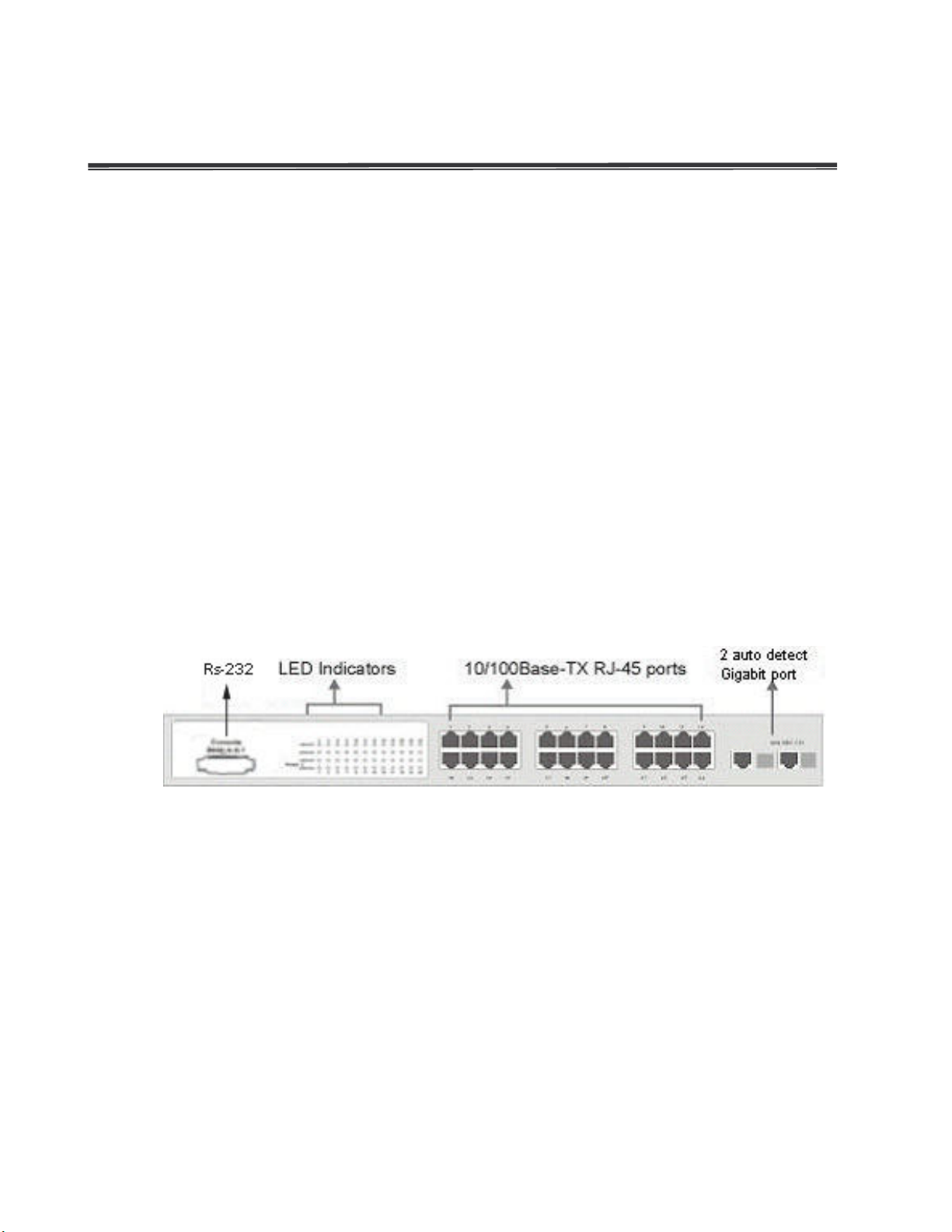
Front Panel
The front panel of the 24 10/100TX plus 2 SFP/Copper managed POE switch consists of
24x 10/100Base-TX RJ-45 ports (Auto MDI/MDIX), 2 auto detect Giga ports, and one
console port. The LED Indicators are also located on the front panel of the Switch.
Front panel of 24 10/100TX plus 2 SFP/Copper managed POE switch
RJ-45 Ports (Auto MDI/MDIX): 24x 10/100 N-way auto-sensing for 10Base-T or
100Base-TX connections.
2 Gigabit combo ports: 2 auto detect 10/100/1000Base-TX UTP or 1000Base-X SFP
LED Indicators
The LED indicators provide a real-time indication of systematic operation status. There
are three LED-Indicators (Link/Activity, Full duplex, power forwarding) for each UTP port
and one power LED for the system unit. The following table provides descriptions of the
7
Page 16
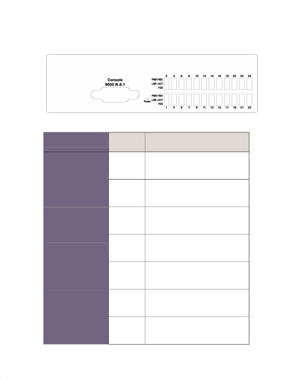
LED statuses and meaning.
LED Status Description
LED indicators
Power
LNK/ACT
Green Power On
Off Power is not connected
Green The port is connecting with the device.
The port is receiving or transmitting
Blinks
data.
Off No device attached.
The port is operating in Full-duplex
Orange
mode.
FDX
Off In half-duplex mode
8
Page 17

The POE Injector function is on and
Power Forwarding
1000(Giga port)
25 & 26 port
100(Giga port)
25 & 26 port
LNK/ACT (Giga
port)
25 & 26 port
Green
power is forwarding the attached PD
device.
Off The POE injector function disables.
Green In 1000Mbps connection speed
Orange In 100Mbps connection speed
Green The port is connecting with the device.
The port is receiving or transmitting
Blink
data.
FDX/COL (Giga
port)
25 & 26 port
Off No device attached
The port is operating in Full-duplex
Orange
mode
Blink Collision of Packets occurs in the port
Off In half-duplex mode
9
Page 18
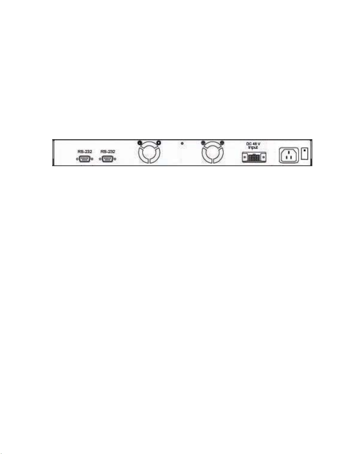
Rear Panel
The two fans, two console ports, and the 3-pronged power plugs are located at the rear
panel of the 24 10/100TX plus 2 SFP/Copper managed POE switch as shown in figure.
The switch also provides one DC 48V input for the extra power connection support and
one DC 48V internal power supply for the power redundant function. The two-console
ports use for connecting with UPS device to manage UPS device or connecting with the
power supply device to manage it.
The rear panel of 24 10/100TX plus 2 SFP/Copper managed POE switch
Desktop Installation
Set the switch on a sufficiently large flat space with a power outlet nearby. The surface
where you put your switch should be clean, smooth, level and sturdy. Make sure there is
enough clearance around the switch to allow attachment of cables, power cord and allow
air circulation.
Attaching Rubber Feet
A. Make sure mounting surface on the bottom of the switch is grease and dust free.
B. Remove adhesive backing from your rubber feet.
C. Apply the rubber feet to each corner on the bottom of the switch. These footpads can
prevent the switch from shock/vibration.
Rack-mounted Installation
The switch come with a rack-mounted kid and can be mounted in an EIA standard size,
19-inch Rack. The Switch can be placed in a wiring closet with other equipment.
Perform the following steps to rack mount the switch:
A. Position one bracket to align with the holes on one side of the switch and secure it
10
Page 19

with the smaller bracket screws. Then attach the remaining bracket to the other side
of the Switch.
B. After attached both mounting brackets, position the 24 10/100TX plus 2 SFP/Copper
managed POE switch in the rack by lining up the holes in the brackets with the
appropriate holes on the rack. Secure the switch to the rack with a screwdriver and
the rack-mounting screws.
[Note] For proper ventilation, allow about at least 4 inches (10 cm) of clearance on the front and 3.4
inches (8 cm) on the back of the Switch. This is especially important for enclosed rack installation.
Power On
Connect the power cord to the power socket on the rear panel of the Switch. The other
side of power cord connects to the power outlet. The internal power supply of the Switch
works with voltage range of AC in the 100-240VAC, frequency 50~60Hz. Check the power
indicator on the front panel to see if power is properly supplied.
11
Page 20
Network Application
PC, workstations, Wireless Access Points and Voice over IP Phones can communicate
each other by directly connecting with 24 10/100TX plus 2 SFP/Copper managed POE
switch.
By using Uplink port, the Switch can connect with another switch or hub to interconnect
other small-switched workgroups to form a larger switched network. Meanwhile, you can
also use fiber ports to connect switches. The distance between two switches via fiber
cable can be up to 550 m (multi-mode fiber) or 10 kilometer (single-mode fiber).
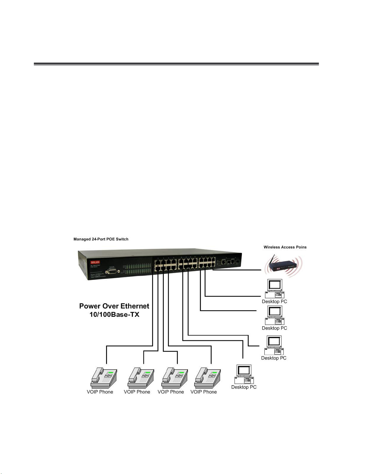
Small Workgroup
The 24 10/100TX plus 2 SFP/Copper managed POE switch can be used as a standalone
switch to which personal computers, VOIP Phones and WAPs, are directly connected.
Small Workgroup Application
12
Page 21
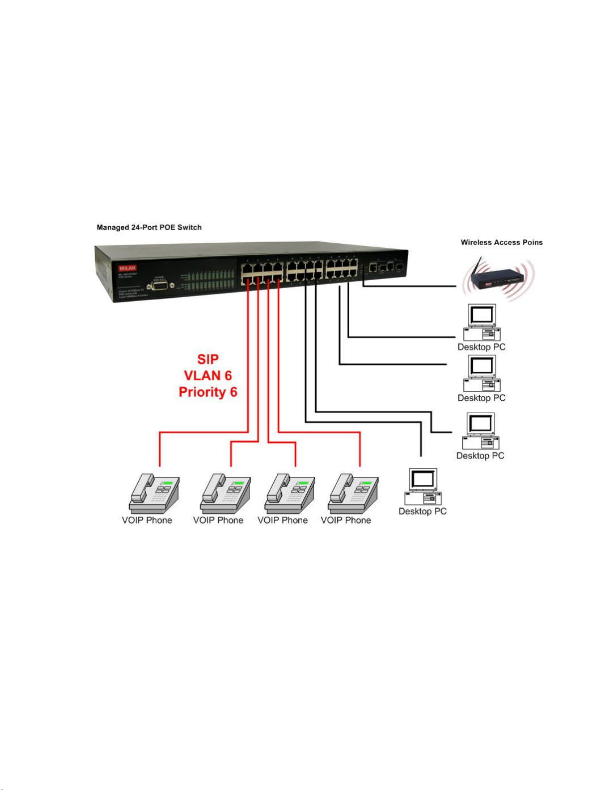
Segment workgroup
For enterprise networks where large data broadcasts are constantly processed, this
switch is an ideal solution for multiple IP services running over the same network.
In the illustration below, you can now interconnect VOIP phones, PCs and WAPs,
segment them and prioritize mission critical traffic.
Segment workgroup Application
Power over Ethernet Application
The 24 10/100TX plus 2 SFP/Copper managed POE switch has POE injector function on
each Ethernet port that can provide the power to the PD device, such as AP or switch. It
can solve the problem of the PD device position limitation for power supply. The following
figure is an example of network application for Power over Ethernet application.
13
Page 22
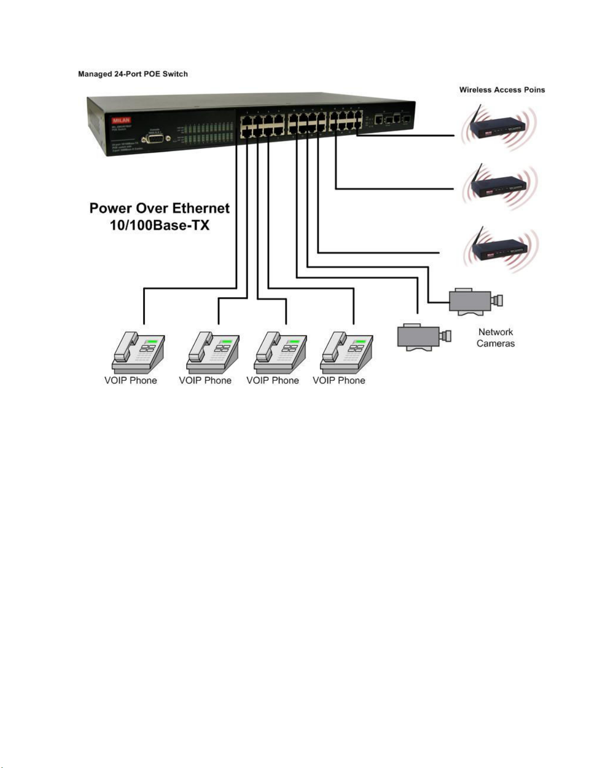
Power over Ethernet Application
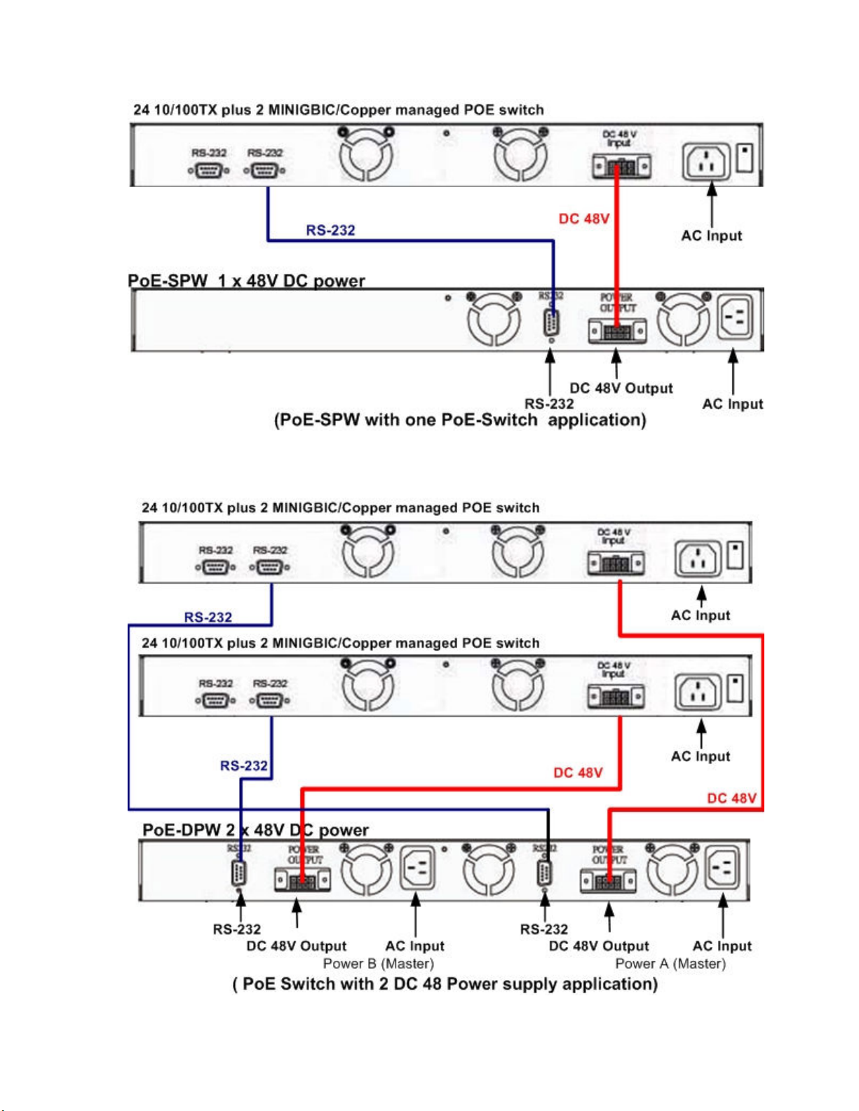
DC Power Input
The 24 10/100TX plus 2 SFP/Copper managed POE switch provides a DC 48V power
input for the extra power supply connection. The DC 48V power input can be used as a
power backup when the AC power is down or no AC power provided in the network
environment. The AC power and the DC 48V power can be connected at the same time,
but the switch will use the DC 48V as the master power input and the AC power as the
secondary or backup power input. The following figures are example of the application. In
the figure, the DC 48V power input connects with the power supply device and through
the RS-232 connection to manage the connected power supply device.
14
Page 23
15
Page 24

Power Redundant
The 24 10/100TX plus one Exp. slot managed POE Switch can connect with UPS to
prevent the power failure.
16
Page 25

Power Redundant Application
17
Page 26
Console Management
Connecting to the Switch
The console port is a female DB-9 connector that enables a connection to a PC or
terminal for monitoring and configuring the Switch. Use the supplied RS-232 cable with a
male DB-9 connector to connect a terminal or PC to the Console port. The Console
configuration (out of band) allows you to set switch for remote terminal as if the console
terminal were directly connected to it.
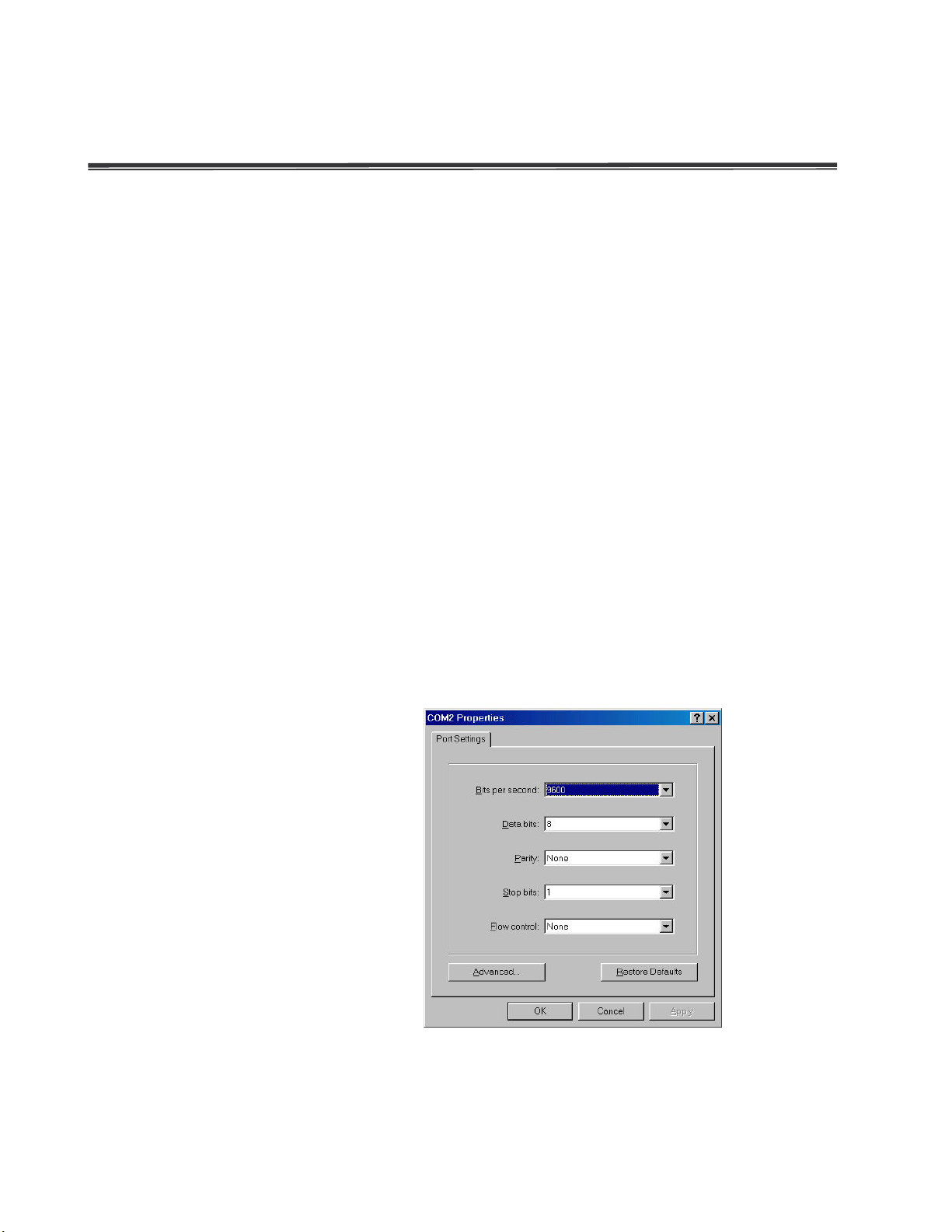
Login in the Console Interface
When the connection between Switch and PC is ready, turn on the PC and run a terminal
emulation program or Hyper Terminal and configure its communication parameters to
match the following default characteristics of the console port:
Baud Rate: 9600 bps
Data Bits: 8
Parity: none
Stop Bit: 1
Flow control: None
The settings of communication parameters
After finished the parameter settings, click “OK“. When the blank screen shows up, press
18
Page 27

Enter key to bring out the login prompt. Key in the “root“(default value) for the both User
name and Password (use Enter key to switch), then press Enter key and the Main Menu
of console management appears. Please see below figure for login screen.
Console login screen
CLI Management
The system supports two types of console management – CLI command and Menu
selection. After you login to the system, you will see a command prompt. To enter CLI
management interface, enter “enable” command. The following tables list the CLI
commands and description.
Commands Level
Access
Modes
Method
Prompt Exit Method About This Mode
Begin a
User EXEC
session with
19
switch>
Enter logout
or quit.
The user commands
available at the user
Page 28

your switch. level are a subset of
those available at the
privileged level.
Use this mode to
• Perform basic tests.
• Display system
information.
The privileged
Privileged
EXEC
Global
Configuratio
n
VLAN
database
Enter the
enable
command
while in user
EXEC mode.
Enter the
configure
command
while in
privileged
EXEC mode.
Enter the vlan
database
command
while in
privileged
switch#
switch
(config)#
switch
(vlan)#
command is advance
mode
Enter disable
Privileged this mode to
to exit.
• Display advance
function status
• Save configures
To exit to
Use this mode to
privileged
configure parameters
EXEC mode,
that apply to your
enter exit or
switch as a whole.
end
Use this mode to
To exit to user
configure
EXEC mode,
VLAN-specific
enter exit.
parameters.
EXEC mode.
20
Page 29

configuration
Interface
configuratio
n
UPS
Enter the
interface
command
(with a
specific
interface)
while in global
configuration
mode
Enter the ups
command
while in
privileged
EXEC mode.
switch
(config-if)#
switch(ups)#
To exit to
global
configuration
Use this mode to
mode, enter
configure parameters
exit.
for the switch and
To exist to
Ethernet ports.
privileged
EXEC mode,
or end.
To exit to
Use this mode to UPS
privileged
parameters for the
EXEC mode,
switch.
enter exit
Enter the poe
command
POE
while in
privileged
EXEC mode.
Commands Set List
System Commands Set
Command
Commands
Level
Global
system name
[word]
mode
To exit to
privileged
switch(poe)#
EXEC mode,
enter exit
Description Defaults
Set switch system
name string
Use this mode to POE
parameters for the
switch.
Example
Switch (config)#
system name
xxx
21
Page 30

configuration
configuration
configuration
configuration
interface configuration
of this
configuration
system
location
[word]
system
description
[word]
system
contact [word]
ip address
[IP-address]
[subnet-mask
] [ gateway]
Global
mode
Global
mode
Global
mode
Global
mode
Set switch system
location string
Set switch system
description string
Set switch system
contact window string
Use the ip address
command to set an IP
address for a switch.
Use the no form
command to remove
an IP address or to
Switch (config)#
system location
xxx
Switch (config)#
system
description xxx
Switch (config)#
system contact
xxx
Switch (config)#
ip address
192.168.1.1
255.255.255.0
192.168.1.254
disable IP processing.
The “write memory” is
write
save configuration
Privileged
[memory|
and the “write
EXEC
terminal]
terminal” is show all
configuration.
Global
Halt and perform a
reload
cold restart
mode
22
Switch# write
memeory
Update NVRAM
to Flash Complete
Switch# write
terminal
Switch (config)#
reload
Page 31

default
configuration
configuration
configuration
Global
Switch (config)#
Restore to default
default
mode
username
[word]
password
[word]
show
accounting
Global
mode
Global
mode
Privileged
EXEC
Changes a login
username. (maximum
10 words)
Specifies a password
(maximum 10 words)
Show username &
password
Switch (config)#
username
xxxxxx
Switch (config)#
password
xxxxxx
Switch# show
accounting
Username: root
Password: root
Switch> show
system-info
show
Show system
User EXEC
system-info
23
information
Name: switch1
location: lab
Description:
layer2 switch
Contact:
somewhere
Serial NO: 1.00
Page 32

Switch# show ip
configuration
address
ip: 192.168.1.1
Privileged
show ip
EXEC
show version User EXEC
Show IP information
Use the show version
user EXEC command
to display version
information for the
hardware and
firmware.
Address subnet:
255.255.255.0
Address
gateway:
192.168.1.254
Switch> show
version
Firmware
version: 1.0
Hardware
version: 3.0
Kernel version:
1.10
Port Commands Set
Command
Commands
Level
Use the fast Ethernet
interface
[FastEthernet
Interface
interface configuration
command
/module
Ethernet] [slot
id] [id]
mode
Use the module
Ethernet interface
configuration
command
24
Description Defaults
Example
Switch (config)#
interface
fastEthernet 0/1
Switch (config)#
interface
moduleEthernet
1/1
Page 33

duplex [full |
configuration
configuration
100 |
configuration
supported for speed
Interface
Use the duplex
configuration
command to specify
the duplex mode of
operation for Fast
Ethernet.
Auto
Switch (config)#
interface
fastEthernet 0/1
Switch (config-if)#
duplex full
half| auto]
speed
[10 | 100 | auto]
mode
Interface
mode
Use the duplex
configuration
command to specify
the duplex mode of
operation for module
Ethernet.
Use the speed
configuration
command to specify
the speed mode of
operation for Fast
Ethernet.
Auto
Auto
Switch (config)#
interface
moduleEthernet
1/1
Switch (config-if)#
duplex full
Switch (config)#
interface
fastEthernet 0/1
Switch (config-if)#
speed 10
speed [10|
1000 | auto]
25
Interface
mode
Use the speed
configuration
command to specify
the speed mode of
operation for module
Ethernet.
The 100Base-FX
module only
100
Switch (config)#
interface
fastEthernet 1/2
Switch (config-if)#
speed 1000
Page 34

The 1000Base-FX
orted for speed
configuration
Use the no form of this
configuration
Use the no form of this
configuration
Use the no form of this
module only
supp
1000 & auto
Use the flow control
configuration
flowcontrol on
or no
flowcontrol
security on or
no security
Interface
mode
Interface
mode
command on Ethernet
ports to control traffic
rates during
congestion.
command to disable
security on the port.
Use the security
configuration
command on Ethernet
ports.
command to disable
On
Disable
Switch (config)#
interface
fastEthernet 0/1
Switch (config-if)#
flowcontrol on
Switch (config)#
interface
fastEthernet 0/1
Switch (config-if)#
security on
priority on
[high | low] or
no priority
26
Interface
mode
security on the port.
Use the priority
configuration
command on Ethernet
ports.
command to disable
security on the port.
Disable
Switch (config)#
interface
fastEthernet 0/1
Switch (config-if)#
priority on high
Page 35

Bandwidth [in |
configuration
Set bandwidth in or out
n
interface
configuration
out] [value]
State [Enable |
Disable]
Interface
mode
Interface
configuratio
mode
rate. The value rage is
(0~999), and zero of
the value is disable
(The module can’t be
setting)
Use the state
configuration
command to specify
the state mode of
operation for Ethernet
ports. Use the disable
form of this command
Disable
Enable
Switch (config)#
interface
fastEthernet 0/1
Switch (config-if)#
bandwidth in 50
Switch (config)#
interface
fastEthernet 0/1
Switch (config-if)#
state disable
show interface
configuration
Interface
mode
to disable the port.
show interface
configuration status
Switch (config)#
interface
fastEthernet 0/1
Switch (config-if)#
show interface
configuration
27
Page 36

show interface
configuration
configuration
show interface statistic
configuration
figuration
status
show interface
accounting
Interface
mode
Interface
mode
show interface actual
status
counter
Switch (config)#
interface
fastEthernet 0/1
Switch (config-if)#
show interface
status
Switch (config)#
interface
fastEthernet 0/1
Switch (config-if)#
show interface
accounting
Interface
show
bandwidth
mode
interface
[FastEthernet
/module
Ethernet] [slot
Interface
con
mode
id] [id]
Trunk Commands Set
Display the bandwidth
of the values
Use the fast Ethernet
interface configuration
command
Switch (config)#
interface
fastEthernet 0/1
Switch (config-if)#
show bandwidth
Switch (config)#
interface
fastEthernet 0/1
Commands
28
Command
Level
Description Defaults
Example
Page 37

Display trunk group
formation. If there
number
Switch # show
configuration
configuration
group 1
show group
[group-ID]
port group
[group-ID]
[port-list] lacp
[on | off] workp
[work ports]
no port group
[group-ID] lacp
[on | off] workp
[work ports]
Privileged
EXEC mode
Global
mode
in
is no group-
in put, display all
trunk groups.
Add trunking
group.
Use the no form of
this command to
delete trunking
group.
Disable
Group Trunk.1:
Ports: 02 03 04
Priority: 0001
Lacp: Enable
Work ports: 0
LACP:
Switch (config)#
port group 1 1-4
lacp on workp 2
Trunk without LACP:
Switch (config)#
port group 1 1-4
lacp off workp 4
port group
Global
[group-ID]
activityport
Set trunking group
port active
mode
[port ID]
29
Switch (config)#
port group 3
activityport 2-4
Trunk.1 Lacp:
Enable
Check OK!
NEW: 2 4
Update finished!!
Page 38

VLAN Commands Set
Command
Commands
Level
Description Defaults
Example
Vlan datatbase
vlanmode
[disable|
portbase|
802.1q | gvrp]
vlan [Group
Name] grpid
[Group ID] port
[Port ID]
Privileged
EXEC mode
VLAN
database
mode
VLAN
database
mode
To enter the VLAN
configuration
interface
To set switch
VLAN mode .Use
the no form of this
command to
restore to default.
Port Base VLAN
Add new Port Base
VLAN
Disable
Switch# vlan
database
Switch(vlan)#
Switch (vlan)#
vlanmode 802.1q
Switch (vlan)# vlan
v2 grpid 2 port 1-4
no vlan [Group
VLAN
Delete port base
Name] [Group
database
VLAN group
ID]
show vlan
mode
Show VLAN of
VLAN
[Group Name]
Group Name or
database
[Group ID] or
Group ID
mode
show vlan
vlan [Group
VLAN
information
Set the port of
name] add
database
some port group
[port ID]
30
mode
Switch (vlan)# no
vlan v2 2
Switch (vlan)#
Show vlan v2 2
Switch (vlan)# vlan
v2 add 5
Page 39

vlan [Group
name] delete
[port ID]
vlan [Group
name]
vlanid [group
ID] port [port
ID] tag
[port ID]
vlan [group
name] add
[port ID]
[tagged |
untagged]
VLAN
Remove the port
database
from it’s port group.
mode
802.1Q | 802.1Q with GVRP VLAN mode
Add new 802.1Q
VLAN
VLAN
database
mode
[group name]:
VLAN name
[group ID]: 2 ~ 4094
[port ID]:
port members 1~9
VLAN
database
mode
Set the port of
some port group
tagged or untagged
Switch (vlan)# vlan
v2 delete 5
Switch(vlan)# vlan
v2 vlanid 2 port 1-4
tag 2-4
Switch(vlan)# vlan
v2 add 5-8 tagged
or
vlan v2 add 5-8
untagged
vlan [group
VLAN
Remove the port
name] delete
database
from its port group.
[port ID]
no vlan [Group
mode
VLAN
Delete 802.1Q
name] or
database
VLAN group
[group ID]
vlan protocol
mode
Add protocol vlan
VLAN
[group name]
[group name]: vlan
database
[protocol
group name
mode
value]
31
Switch(vlan)# vlan
v2 delete 5
Switch (vlan)# no
vlan v2
Switch (vlan)# no
vlan v2 2
Switch(vlan)# vlan
protocol v3 ip
vlanid 2 port 5-8
tag 6,8
Page 40

banyan
range
vlanid [group
ID] port [port
ID] tag [port
ID]
IP-ip
ARP-arp
Appletalk-app
Appletalk_AARP-ap
p_arp
Novell_IPX-ipx
Banyan_vines-bany
an_c4
Banyan_vines-bany
an_c5
Banyan_vines-bany
an_ad
Decent_mop_01-de
cent_01
Decent_mop_02-de
Switch(vlan)# vlan
protocol v3 arp
vlanid 2 port 5-8
tag 6,8
Switch(vlan)# vlan
protocol v3
vlanid 2 port 5-8
tag 6,8
cent_02
Decent_dpr-decent
_dpr
Decent_LAT-decen
t_lat
Decent_LAVC-dece
nt_lavc
IBM SNA-ibm
X.75 internet-x75
X.25 Layer3-x25
[VLAN ID]: 2 ~ 4094
[port ID]:
port ID 1~10
vlanidrange
[VLAN ID
32
VLAN
database
Set VLAN ID
[1~255] range 0
Switch (vlan)#
vlanidrange 2
Page 41

range] mode [256~511] range 1
[512~767] range 2
[768~1023] range 3
[1024~1279] range
4
[1280~1535] range
5
[1536~1791] range
6
[1792~2047] range
7
[2048~2303] range
8
[2304~2559] range
9
OLD: 0
NEW: 2
VLAN protocol
[Group name]
add [port ID]
[tagged |
VLAN
database
mode
[2560~2815] range
10
[2816~3071] range
11
[3072~3327] range
12
[3328~3583] range
13
[3584~3839] range
14
[3840~4094] range
15
Set the port of
some port group
tagged or untagged
Switch (vlan)# vlan
protocol v2 add 5
tagged
33
Page 42

untagged]
how
how
VLAN protocol
[Group name]
delete [port ID]
show vlan
[Group name]
[Group ID] or
show vlan
show vlan
protocol
VLAN
database
mode
VLAN
database
mode
VLAN
database
mode
Remove the port
from its port group.
Show VLAN of
Group Name or
VLAN ID
information
vlanid: 1 ~ 4094
show protocol vlan
Protocol
ip
ipx
netbios
Switch (vlan)# vlan
protocol v2 delete
5
Switch (vlan)# s
vlan v2 2
Switch (vlan)# s
vlan protocol
port [port ID]
pvid [port VID]
ingressfilter1
[on | off]
ingressfilter2
[on | off]
VLAN
database
mode
Set Port PVID and
Ingress Filter
Rules1 & Ingress
Filter Rules2
Switch (vlan)# port
2 pvid 2
ingressfilter1 off
ingressfilter2 on
34
Page 43

Switch (vlan)# s
how
tree
port 2
VLAN
show port [port
database
ID]
mode
Spanning Tree Commands Set
Command
Commands
Level
show Port PVID
and Ingress Filter
Port ID: 2
Port Vid: 2
Rules1 & Ingress
Filter Rules2
Ingress 1 Filter:
Disable
Ingress 2 Filter:
Enable
Description Defaults Example
Switch> show
spanning-tree
System:
show
spanning-tree
User EXEC
mode
Display a summary
of the spanning-
states.
Priority: 32768
Max Age: 20
Hello Time: 2
Forward Delay: 15
Priority: 32768
Mac Address:
004063800030
Root_Path_Cost: 0
Root Port: we are
root
Max Age: 20
Hello Time: 2
Forward Delay: 15
35
Page 44

spanning-tree
tree
configuration
command to enable
Protocol (STP). Use
restore
no
configuration
configuration
[on / off]
or
no spanning-
Global
mode
Use the
spanning-tree
global configuration
Spanning Tree
the no form of the
command to
to default
Use the
spanning-tree
max-age global
Switch (config)#
spanning-tree on
Disable
or
Switch (config)#
spanning-tree
spanning-tree
priority [number]
spanning-tree
max-age
[seconds]
Global
mode
Global
mode
configuration
command to
change the priority.
Use the no form of
this command to
return to the default
interval.
Use the
spanning-tree
max-age global
configuration
command to
change the interval
between messages
32768
20 sec
Switch (config)#
spanning-tree
priority 32767
Switch (config)#
spanning-tree
max-age 15
36
the spanning tree
receives from the
root switch. If a
Page 45

switch does not
configuration
command to specify
bridge protocol data
receive a bridge
protocol
data unit (BPDU)
message from the
root switch within
this interval, it
recomputes the
Spanning Tree
Protocol (STP)
topology. Use the
no form of this
command to return
spanning-tree
hello-time
[seconds]
Global
mode
to the default
interval.
Use the
spanning-tree
hello-time global
configuration
the interval
between hello
units (BPDUs). Use
the no form of this
command to return
to the default
2 sec.
Switch (config)#
spanning-tree
hello-time 3
37
interval.
Page 46

stp-path-cost
configuration
command to set the
bps
configuration
command to set the
[number]
Interface
mode
Use the
spanning-tree cost
interface
configuration
path cost for
Spanning Tree
Protocol (STP)
calculations. In the
event of a loop,
spanning tree
considers the path
cost when selecting
10 Mbps
– 100
100 M
– 10
Switch (config)#
interface
fastEthernet 0/2
Switch (config-if)#
stp-path-cost 20
spanning-tree
forward-time
[seconds]
Global
mode
an interface to
place into the
forwarding state.
Use the no form of
this command to
return to the default
value.
Use the
spanning-tree
forward-time global
configuration
forwarding-time for
the specified
15 sec.
Switch (config)#
spanning-tree
forward-time 20
38
spanning-tree
instances. The
forwarding time
determines how
Page 47

long each of the
configuration
the root switch. Use
listening and
learning states last
before the port
begins forwarding.
Use the no form of
this command to
return to the default
value.
Use the
spanning-tree
port-priority
interface
stp-path-priority
[number]
QOS Commands Set
Commands
Interface
mode
Command
Level
configuration
command to
configure a port
Switch (config)#
interface
fastEthernet 0/2
128
priority that is used
when two switches
tie for position as
Switch (config-if)#
stp-path-priority
127
the no form of this
command to return
to the default value.
Description Defaults Example
39
Page 48

configuration
of this command
control
configuration
configuration
configuration
no
qos
storm-control
[5|10|15|20|25|
off (%)] or no
storm-control
qos
low-priority-del
ay-bound
[on|off] [sec.]
or no qos
low-priority-del
ay-bound
qos level
[priority]
Global
mode
Global
mode
Global
mode
Enable/Disable
broadcast storm
control. Use the no
form
to restore to default.
Enable/Disable low
priority delay board.
Use the no form of
this command to
restore to default.
[Priority] 0~7
OFF
OFF
0~3 LOW
4~7 HI
Switch (config)#
qos storm-
5
Switch (config)#
qos
low-priority-delay
-bound on 1
Switch (config)#
qos level 2,3
no qos level
[priority]
Global
mode
[Priority] 0~7
0~3 LOW
4~7 HI
Switch (config)#
qos level 0-7
40
Page 49

configuration
WRR:
configuration
Switch (config)#
qos queuepolicy
wrr hi 7 low 1
qos
queuepolicy
[Policy] hi
[number] low
[number]
qos
bridge-delay-b
ound [sec.]
no qos
bridge-delay-b
ound
Global
mode
Global
configuration
mode
[Policy]:fcfs: first in
and first out
wrr: weight round
robin
ahbl: all high before
low.
[Priority] Hi:1~7
Low:1
Set qos bridge delay
bound
Use the no form of
this command to
restore to default.
First Come First
Served:
WRR
Switch (config)#
Hi 2
qos queuepolicy
Low 1
fcfs
All High before
Low:
Switch (config)#
qos queuepolicy
ahbl
Switch (config)#
qos
OFF
bridge-delay-bou
nd 1
Global
show qos
storm-control
Show broadcast
storm control.
mode
41
Switch (config)#
show qos
storm-control
QOS storm control
mode: ENABLE
Page 50

configuration
configuration
configuration
bound
configuration
configuration
Displays the details of
show qos
policy
show qos
low-priority-del
ay-bound
show qos
bridge-delay-b
ound
Global
mode
Global
mode
Global
mode
Show qos policy
Show low priority
delay board.
Show bridge delay
bound
Switch (config)#
show qos policy
Qos Mode: WRR
Switch (config)#
show qos
low-priority-delay
-bound
Qos low priority
delay bound: 1
Switch (config)#
show qos
bridge-delay-bou
nd
bridge-delay-
IGMP Commands Set
Command
Commands
Level
Global
igmp [on | off]
mode
igmp-query
Global
[auto |enable |
disable]
show ip igmp
profile
mode
Privileged
EXEC mode
Description Defaults
Enable /Disable
IGMP snooping
Off
function
Modify IGMP query
Disable
mode
an IGMP profile entry.
5
Example
Switch (config)#
igmp on
Switch (config)#
igmp-query enable
Switch# show ip
igmp profile
42
Page 51

224.1.1.1
configuration
this command to use
table
table
table
table
Mac / Filter Table Commands Set
Command
Commands
Level
mac-address-ta
ble aging-time
[on | off]
Global
mac-address-ta
ble aging-time
mode
[sec.]
or no
mac-address-ta
Description Defaults
Use the
mac-address-table
aging-time global
configuration
command to set the
length of time that a
dynamic entry
remains in the MAC
address table after
300 secs
the entry is used or
updated.
Use the no form of
IP
VID Port
10 1,2,6
Example
Switch (config)#
mac-address-
aging-time on
Switch (config)#
mac-address-
aging-time 333
(Disable)
Switch (config)#
mac-address-
aging-time off
ble aging-time
43
Or
the default
Switch(config)# no
aging-time interval.
mac-address-
The aging time
aging-time
applies to all VLANs.
Page 52

static
configuration
Use the
addresses to the
table
configuration
entries from the MAC
table
table
table
mac-address-ta
ble table [
| filter] hwaddr
[MAC address]
vlanid
[VLAN-ID]
no
mac-address-ta
ble [static |
filter] hwaddr
[MAC address]
Interface
mode
Interface
mode
mac-address-table
static to add static |
filter
MAC address table.
Use the no form of
this command to
remove static entries
from the MAC
address table.
Use the no
mac-address-table
privileged EXEC
command to delete
N/A
Switch (config)#
interface
fastEthernet 0/2
Switch (config-if)#
mac-address-
static hwaddr
004063112233
vlanid 10
Switch (config)#
interface
fastEthernet 0/2
Switch (config-if)#
no
mac-address-
vlanid
[VLAN-ID]
show
mac-address-ta
ble [static |
filter]
show
mac-address-ta
ble
aging-time
Privileged
EXEC mode
Privileged
EXEC mode
address table.
Use the show
mac-address-table
user EXEC
command to display
the MAC address
table.
Use the show
mac-address-table
user EXEC
command to display
static hwaddr
004063112233
vlanid 10
Switch # show
mac-address-
static
Switch# show
mac-address-
aging-time
MAC Address
44
Page 53

the MAC address
table.
aging-time: 300
45
Page 54

configuration
location
configuration
contact
configuration
configuration
Use the no form of
configuration
SNMP Commands Set
Command
Commands
Level
Description Defaults
Example
snmp
system-name
[word]
snmp
system-
[word]
snmp
system-
[word]
snmp
community-strin
gs [word] right
[RO | RW]
Or
no snmp
community-strin
gs [word]
Global
mode
Global
mode
Global
mode
Global
mode
Set SNMP agent
system name
Set SNMP agent
system location
Set SNMP agent
system contact
Add SNMP
community string.
this command to
remove the
specified
community.
N/A
N/A
N/A
PUBLIC
RO
Switch (config)#
snmp system-name
l2switch
Switch (config)#
snmp
system-location lab
Switch (config)#
snmp
system-contact
where
Switch (config)#
snmp
community-strings
public right RW
Switch(config)#
no snmp
community-strings
public right rw
snmp-server
host
[IP-address]
community
[word]
46
Global
mode
Configure SNMP
server host
information and
community string
N/A
Switch(config)#
snmp-server host
192.168.1.50
community
public
Page 55

configuration
configuration
fastEthernet
No snmp-server
host [IP
address]
community
[word]
snmp
Global
system-name
[word]
mode
Port Mirroring Commands Set
Command
Commands
Level
Switch(config)# no
snmp-server host
192.168.1.50
community public
Switch (config)#
Set SNMP agent
N/A
snmp system-name
system name
l2switch
Description Defaults Example
port monitor
[RX|TX|both]
[port ID]
Or
no port monitor
Interface
mode
Use the port
monitor interface
configuration
command to
enable Switch
Port Analyzer
(SPAN) port
monitoring on a
port. Use the no
form of this
command to
return the port to
its default value.
N/A
Switch (config)#
Interface
0/8
Switch (config-if)# port
monitor both 3
47
Page 56

Use the show port
Switch # show port
configuration
monitor
State: Enable
AnalysisPortId: 8
show port
monitor
Privileged
EXEC mode
802.1x Commands Set
monitor privileged
EXEC command
to display the
ports for which
Switched Port
Analyzer (SPAN)
port monitoring is
enabled.
Port 01 TxRx: Monitor
Port 02 TxRx:
Port 03 TxRx:
Port 04 TxRx:
Port 05 TxRx:
Port 06 TxRx:
Port 07 TxRx:
Port 08 TxRx: Analysis
Port 09 TxRx:
Port 10 TxRx:
OK.
Command
Commands
Description Defaults Example
Level
Display a summary of
User EXEC
show 8021x
the 802.1x properties
mode
and also the port sates.
Use the 802.1x global
configuration command
8021x [on | off]
Global
to enable 802.1x
or
protocols. Use the no
No 8021x
mode
form of the command to
restore to default
48
Switch> show
N/A
8021x
Switch (config)#
Disable
8021x on
Page 57

configuration
configuration
configuration
configuration
configuration
8021x system
radiusip
[IP address]
Or
no 8021x
system
radiusip
8021x system
sharekey
[number]
Or
no 8021x
system
sharekey
Global
mode
Global
mode
Use the 802.1x system
radius IP global
configuration command
to change the radius
server IP.
Use the no form of this
command to return to
the default interval.
Use the 802.1x system
sharekey global
configuration command
to change the shared
key value.
Use the no form of this
command to return to
the default interval.
Switch (config)#
8021x system
radiusip
192.168.1.1
192.16
8.16.3
(Default)
Switch(config)#
no 8021x system
radiousip
Switch (config)#
8021x system
sharekey 123456
123456
(Default)
78
Switch (config)#
no 8021x system
sharekey
8021x system
serverport
[Port Number]
8021x system
accountport
[Port Number]
Global
set radius server port 1812
mode
Global
set accounting port 1813
mode
Global
8021x system
set NAS ID
nasid [word]
mode
49
Switch (config)#
8021x system
serverport 1815
Switch (config)#
8021x system
accountport 1816
NAS_L
Switch (config)#
2_
8021x system
SWITC
nasid test1
H
Page 58

configuration
Use the 802.1x misc
configuration
no
configuration
configuration
configuration
8021x misc
quietperiod
[sec.]
Or
no 8021x misc
quietperiod
8021x misc
txperiod [sec.]
Or
no 8021x
txperiod
Global
mode
Global
mode
quiet period global
configuration command
to specify the quiet
period value of the
switch.
Use the no form of this
command to return to
the default interval.
Use the 802.1x misc TX
period global
configuration command
to set the TX period.
Use the no form of this
command to return to
Switch (config)#
8021x misc
quietperiod 10
60 sec.
(Default)
Switch(config)#
no 8021x misc
quietperiod
Switch (config)#
8021x misc
txperiod 5
30 sec.
(Default)
Switch(config)#
8021x misc
8021x misc
supptimeout
[sec.]
8021x misc
servertimeout
[sec.]
8021x misc
maxrequest
[Number]
Global
mode
Global
mode
Global
mode
the default value.
Set the period of time
the switch wait for a
supplicant response to
an EAP request.
Set the period of time
the switch wait for a
server response to an
authentication request.
Set the number of
authentication that must
time-out before
30 sec.
30 sec.
2
txperiod
Switch (config)#
8021x misc
supptimeout 30
Switch (config)#
8021x misc
servertimeout 50
Switch (config)#
8021x misc
maxrequest 2
50
Page 59

8021x misc
configuration
configuration
reauthperiod
[sec.]
Global
mode
authentication fails and
the authentication
session ends.
Set the period of time
after which clients
connected must be
re-authenticated.
Use the 802.1x port
state interface
configuration command
to set the state of the
selected port.
3600
Switch(config)#
8021x misc
reauthperiod 20
8021x prostate
[reject | accept
| authorize |
disable]
Interface
mode
Reject: the
specified port is
required to be held in
the unauthorized
state.
Accept: the
specified port is
required to be held in
the Authorized state.
Authorized: the
specified port is set to
the Authorized or
Unauthorized state in
accordance with the
outcome of an
Switch (config)#
interface
fastethernet 0/3
N/A
Switch (config-if)#
8021x portstate
accept
authentication
exchange between
the Supplicant and the
51
Page 60

[TFTP IP
tftp:config.text
TFTP Commands Set
Command
Commands
Level
authentication server.
Disable: The
specified port is
required to be held in
the Authorized state.
Description Defaults
Example
Switch (config)#
copy
copy
flash:config.te
xt tftp
address] [file
name]
flash
[TFTP IP
address] [file
name]
Global
configuration
mode
Global
configuration
mode
Backup configure file
command
Restore configure file
command
flash:config.text
tftp
Server
IP:192.168.1.1
Image
Filename:backup.
dat
Switch(config)#
Tftp:config.text
flash
Server
IP:192.168.1.1
Image
Filename:restore.
tftp:firmware
flash
[TFTP IP
Global
Update firmware
configuration
command
mode
52
dat
Switch (config)#
Tftp:firmware
flash
Page 61

address]
[file name]
UPS Commands Set
Command
Commands
Level
status UPS mode
Description Defaults
Display a summary of
the UPS status.
Server
IP:192.168.1.1
Image
Filename:image.bi
n
Example
Switch
(ups)#status
Input Output
Voltage…….
Info UPS mode Show UPS information
UPS will perform the
Test 10 UPS mode
self-test for 10
seconds.
POE Commands Set
Command
Commands
Level
Description Defaults
Switch (ups)#
info
Company Name
:xxx
Model :xxx
Version :xxx
Switch (ups)#
test10
test OK
Example
53
Page 62

status POE mode Show POE information
Switch(poe)#
status
Switch(poe)#
setpm [on |
off]
setlimit
[value]
portebl
[enable |
disable]
[ports]
POE mode
POE mode
POE mode
Enabling or disabling
the power
management.
Enabling or disabling
total power output limit.
When is enabling, the
total power output limit
will follow the value
that set in power limit
max.
Enabling or disabling
the port POE injected
function.
setpm on
Set Power
Management
Enable
Switch(poe)#
setlimit 100
Switch(poe)#
portebl disable
1-3
portcls
Enabling or disabling
[enable |
POE mode
per port power limit by
disable]
classification.
[ports]
portmng
Enabling or disabling
[enable |
POE mode
per port power limit by
disable]
management.
[ports]
54
Switch(poe)#
portcls enable
1-3
Switch(poe)#
portmng enable
2-5
Page 63

portleg
imit
configuration
configuration
[enable |
disable]
[ports]
POE mode
Enabling or disabling
per port legacy
detection.
Switch(poe)#
portleg enable
3-6
portpri
[critical | high
POE mode
| low] [ports]
portplm
POE mode
[value] [ports]
System log Commands Set
Command
Commands
Level
show
User EXEC Display system log.
systemlog
Set port priority for the
power supply
management.
Set per port power l
Max.
Description Defaults
switch# show
Switch(poe)#
portpri critical 2
Switch(poe)#
portplm 12200
5-7
Example
Switch>
show systemlog
systemlog
show
systemlog
Privileged
EXEC
Show system log client
& server information
Global
systemlog ip
[IP address]
Set System log server
IP address.
mode
systemlog
Global
Enable or disable
[enable |
system log mode
disable]
55
mode
Syslog Client:
Enable
Syslog Server Ip:
192.168.16.2
Switch(config)#
systemlog ip
192.168.1.100
Switch(config)#
systemlog
enable
Page 64

configuration
configuration
configuration
SNTP Commands Set
Command
Commands
Level
Description Defaults
Example
Switch(config)#
sntp [enable |
disable]
sntp ip [IP
address]
sntp
timezone
[value]
Global
mode
Global
mode
Global
mode
Enable/Disable SNTP. Disable
Set SNTP server IP
address.
Set time zone.
sntp enable
Switch(config)#
sntp disable
switch#sntp ip
192.168.16.123
Switch(config)#
sntp timezone 8
56
Page 65

Menu Management
After you login to the system, you will see a command prompt. To enter Menu
management interface, enter “
The following configure steps are based on the software kernel version v1.01.
1. Provide a menu line interface to manage and monitor the switch. User can use
windows Hyper Terminal program through the console port to connect the switch for
configuration.
2. The default user name and password is “root”.
There are 8 selections as follow.
Status and Counters: Show the status of the switch.
Switch Configuration: Configure the switch.
Protocol Related Configuration: Configure the protocol function.
System Reset Configuration: Restart the system or reset switch to default
configuration.
Power menu: configure the UPS function.
menu
” command. You will see the main menu interface.
POE menu: configure the POE function.
Save Configuration: save the current configuration into the system memory.
Logout: Exit the menu line program.
57
Page 66

Main menu line interface
Control Key description:
The control keys provided in all menus:
Tab/Backspace: Move the vernier to configure item.
Enter: Select item.
Space: Toggle selected item to next configure or change the value.
Esc: to exit the current action mode.
58
Page 67

Status and Counters
In Status and Counters, you can view Port status, counters, and configure system
parameter.
Status and Counters main configuration interface
Port Status
It displays status of each port. Select the <Previous Page> action to display previous
page. And, select the <Next page> action to display next page.
Type: display port connection speed.
Link: display port statuses link status. When the port is connecting with the device
and work normally, the link status is “UP”. Opposite is “Down”.
State: The port current status.
Negotiation: display the auto negotiation status.
Speed Duplex: display port duplex mode.
FC: display the flow control status is “enable” or “disable”.
59
Page 68

BP: display backpressure status.
Bandwidth In/Out:
display bandwidth In/out control status.
Priority: display the port priority status.
Security: display the port security status.
Port status interface
Port Counters
It displays the current port counter information. Select the <Refresh> to get newest
counter information. Select <Clear> to set all ports counter to 0. Select <Next Page> to
go to next page. Select <Previous Page> to back to last page.
60
Page 69

System Information
Port counter information interface
• It displays the system parameter.
• System Name: the name of device.
• System Location: where the device is located.
• System Description: the name of device type.
• Firmware Version: the switch’s firmware version.
• Hardware Version: the switch’s Hardware version.
• Kernel Version: the system kernel software version.
• MAC Address: The unique hardware address assigned by manufacturer.
• Module Information: display information of installed module.
61
Page 70

System Information interface
62
Page 71

Switch Configuration
In Switch Configuration, it has 8 main functions – Administration, Port, Trunk, Port
Mirroring, VLAN, Priority, MAC Address, and Misc Configuration. Under each function,
there are more sub-functions. We will describe in following paragraph.
Switch Configuration interface
Administration Configuration
In Administration Configuration, you can configuration system parameter, IP, login
username, password, and SNTP configuration.
63
Page 72

Administration Configuration main interface
Device Information
You can configure the device information.
1. Select <Edit> action to configure.
2. Name: assign the name for the switch.
3. Description: a short description for the switch.
4. Location: the switch location, ex: Taipei.
5. Contact: the contact person or information.
6. Select <Apply> action to apply the configuration.
64
Page 73

Device Information interface
IP Configuration
You can configure the IP for this switch. The system has the default IP address. You can
re-configure or use the default value.
1. Select the <Edit>
2. DHCP Client: “Enable” is to get IP from DHCP server. “Disable” is opposite. The
DHCP client function only works if you haven't assigned a static IP address that
different than the switch default IP. Once the default IP has been changed the
DHCP will not effective and the switch will continue using the manually entered static
IP. If you have changed the switch to a static IP address, you can set the IP address
back to its default IP address or you can reset the switch back to factory default. And
then you can enable the DHCP client function to work.
3. IP Address: assign the switch IP address. The default IP is 192.168.1.77
4. Subnet Mask: assign the switch IP subnet mask.
5. Gateway: assign the switch gateway. The default value is 192.168.1.254
6. Select <Apply> action to apply the configuration.
[Note] Always restart the switch after finished the setup to apply the new IP setting.
65
Page 74

IP Configuration interface
User Name Configuration
You can change the console and web management login user name.
1. Select the <Edit>
2. Enter the new user name
3. Select the <Apply>
66
Page 75

Password Configuration
User Name Configuration interface
You can change the console and web management login password.
1. Select the <Edit>
2. Old Password: enter the old password.
3. New Password: enter the new password.
4. Enter Again: reenter the new password for confirmation.
5. Select the <Apply>
67
Page 76

Password Configuration interface
SNTP Configuration
You can configure the SNTP (Simple Network Time Protocol) settings. The SNTP allows
you to synchronize switch clocks in the Internet.
SNTP Client: enable or disable SNTP function to get the time from the SNTP server.
UTC Timezone: set the switch location time zone.
Server IP: set the SNTP server IP address.
68
Page 77

SNTP Configuration Interface
System log Client Configuration
You can configure the switch as the system log client that can view the system log
information that from the system log server that you have assigned.
1. Select <Edit>
2. Client Mode: enabling or disabling the system log client function. “Enable” can view
the system log information from the assigned system log server.
3. Server IP: assigned the system log server IP.
4. Select <Apply> to apply the configuration.
69
Page 78

System log Client Configuration Interface
Port Configuration
You can set up every port status.
1. Select <Edit>
2. Use “Tab/Backspace” key to move between items.
3. Type: display port connection speed.
4. State: Current port status. The port can be set to disable or enable mode. If the port
setting is disable then will not receive or transmit any packet.
5. Negotiation: set auto negotiation function of port.
6. Speed/Duplex: set the port link speed and duplex mode.
7. FC: enable or disable Flow control function (Flow control for full duplex link mode).
8. BP: enable or disable Back Pressure function (Backpressure for half duplex mode).
9. Bandwidth In/ Out: per port packet transmission rate control. Per level is 100Kbps. It
supports individual control method of TX and RX.
10. Priority: set packet of port to high or low priority queue.
11. Security: enable or disable port security function.
12. Select the <Apply>.
70
Page 79

Port Configuration interface
Trunk Configuration
You can configure port trunk group.
1. Select <Edit>
2. Using “Tab” key move to the port that want to be added as trunk group.
3. Using “Space” key to mark the port.
4. Using Tab key move to Trunk # (ex. Trunk1, Trunk2…) to change the Trunk # value to
Static, LACP, or Disable.
5. Apply the configuration by selecting <Apply>.
71
Page 80

Trunk Configuration interface
Port Mirroring Configuration
The port mirroring is a method for monitor traffic of switched networks. The specific port
can monitor traffic through the mirror ports. The monitored ports in or out traffic will be
duplicated into monitoring port.
1. Select the <Edit>
2. Mirroring State: select the port-mirroring mode. The default value is “Disable”. To
start port mirroring, you must select one of port mirroring mode.
RX: RX packet only
TX: TX packet only
Both: RX and TX packet
72
Page 81

Port Mirroring interface
3. Analysis port: Set the destination port of mirroring packet. All of the packets of
mirroring port will be duplicated and sent to Analysis port.
4. Port State: Select the ports that want to be mirrored.
5. Use “Space” key to mark the mirroring port can.
6. Select the <Apply>.
Port Mirroring interface
73
Page 82

VLAN Configuration
You can configure VLAN group in VLAN Configuration. There are four functions in VLAN
Configuration mode: VLAN Configuration, Create a VLAN Group, Edit/Delete VLAN
Group and Group Sorted Mode. Follow the below description to configure VLAN.
VLAN Configuration Main interface
VLAN Configure
Before starting to configure VLAN, you must select the VLAN mode in VLAN Configure
function. Otherwise, user cannot create any new VLAN.
1. Select the <Edit>.
2. Select the VLAN mode by using “Tab” key. There are two VLAN modes: PortBase
mode and 802.1Q mode. When select the 802.1Q VLAN mode, you need to
configuration the following settings.
802.1Q VLAN mode: configuration VLAN ID, Ingress Filter, and Acceptable
Frame Type.
VLAN ID Range: Type the PVID. The PVID will only assign to the Ingress
packets, not for all packets.
74
Page 83

Ingress Filter: It matches that Ingress Filtering Rule 2 on web. Drop
untagged frame. Press “Space” key to select drop or forward the untagged
frame.
Acceptable Frame type: It matches that Ingress Filtering Rule 1 on web.
Only forward packets with VID matching this port’s configured VID. Press
“Space” key to choose “forward” or “drop” the frame that VID not matching
this port’s configured VID.
3. Select <Apply> to apply the configuration.
[Note] when the VLAN mode changed that user has to restart the switch for valid
value.
VLAN Configure interface
Create VLAN Group
Create Port-Based VLAN
1. Select <Edit>.
2. VLAN Name: Type a name for the new VLAN, ex: VLAN01.
3. Group ID: Type the VLAN group ID.
75
Page 84

4. Member: Press ”Space” key to change the member value. There are two types to
selected:
a. Member: the port is a member port.
b. NO: it means that port is NOT a member port.
5. Press “ESC” key to go back action menu line.
6. Select <Apply> to apply the configuration.
[Note] If you have configured the trunk groups, you can see it (ex: Trunk1, Trunk2…)
in the port list. You also can configure the trunk group as the VLAN member.
Create VLAN Group: PortBase interface
Create 802.1Q VLAN
1. Enable security VLAN setting: select to enable or disable security VLAN group.
When you select to enable security VLAN group, only the members in this VLAN
group can access to the switch. The steps of setting security VLAN refer to the
following step 2~ 8. After you configured the security VLAN group, you can continue
to create other VLAN groups. When you didn’t select to configure security VLAN
group, then just create VLAN group refer to following step 2 ~ 8.
[Note] There is only one security VLAN group.
76
Page 85

2. Select <Edit>.
3. VLAN Name: Type a name for the new VLAN, ex: VLAN01.
4. VLAN ID: Type a VID. The default is 1. There are 256 VLAN groups to provided
configure.
5. Protocol VLAN: Press “Space” key to choose protocols type.
6. Member: Press “Space” key to change the member value.
Untagged: this port is the member port of this VLAN group and outgoing frames
are NO VLAN-Tagged frames.
Tagged: this port is the member port of this VLAN group and outgoing frames
are VLAN-Tagged frames.
NO: it means that the port is NOT member of this VLAN group.
7. Press “ESC” key to go back action menu line.
8. Select <Apply> to apply the configuration.
[Note] If the trunk groups exist, you can see it (ex: Trunk1, Trunk2…) on the port list,
and you can configure it is the member of the VLAN or not.
77
Page 86

Create VLAN Group: 802.1Q interface
Edit / Delete VLAN Group
User can edit or delete a VLAN group.
1. Select <Edit> or <Delete> action.
2. Select the VLAN group that you want to edit or delete, then press enter.
3. In <Edit> action, user can modify the member port and remove some member ports
from this VLAN group.
[Note]
1. The VLAN Name and VLAN ID cannot modify.
2. In 802.1Q VLAN mode, the default VLAN can’t be deleting.
3. In Port Base VLAN mode, there is no default VLAN.
78
Page 87

Edit/Delete a VLAN Group interface
Group Sorted Mode
You can select VLAN groups sorted mode: (1) Name (2) VLAN ID.
In the Edit/Delete a VLAN group page will display the result.
1. Select <Edit>
2. Use “Space” key to select the sort mode.
3. Select <Apply>
79
Page 88

Group Sorted Mode interface
80
Page 89

Priority Configuration
You can configure port priority level. There are 0~7-priority level can map to high or low
queue.
1. Select <Edit>.
2. Press “Space” key to select the priority level mapping to high or low queue.
3. Qos Mode: User can select the ratio of high priority packets and low priority packets.
First Come First Service: the switch will process the packet that is coming first.
All High Before low: the packet priority is high will be process before the packet
priority is low.
Weight Round Ration 2:1: the switch will process 2 high priority packet first, the
process 1 low priority packet.
Weight Round Ration 3:1: the switch will process 3 high priority packet first, the
process 1 low priority packet.
Weight Round Ration 4:1: the switch will process 4 high priority packet first, the
process 1 low priority packet.
Weight Round Ration 5:1: the switch will process 5 high priority packet first, the
process 1 low priority packet.
Weight Round Ration 6:1: the switch will process 6 high priority packet first, the
process 1 low priority packet.
Weight Round Ration 7:1: the switch will process 7 high priority packet first, the
process 1 low priority packet.
4. Press “ESC” goes back action menu line.
5. Select <Apply> to apply all configure value.
81
Page 90

Priority Configuration interface
MAC Address Configuration
When you add a static MAC address, it remains in the switch's address table, regardless
of whether the device is physically connected to the switch. This saves the switch from
having to re-learn a device's MAC address when the disconnected or powered-off device
is active on the network again. You can add / modify / delete a static MAC address.
82
Page 91

MAC Address Configuration interface
83
Page 92

Static MAC Address
Add the Static MAC Address
You can add static MAC address in switch MAC table.
1. Select <Add> <Edit> key to add the static MAC address.
2. MAC Address: Enter the MAC address of the port that should permanently forward
traffic, regardless of the device network activity.
3. Port No.: press “Space” key to select the port number.
4. Press “ESC” to go back action menu line.
5. Select <Apply> to apply all configure value.
Add Static MAC Address interface
Edit static MAC address
1. Press <Edit>.
2. Choose the MAC address that you want to modify and then press “Enter”.
3. Press <Edit> key to modify.
4. Press “ESC” to go back action menu line.
5. Select <Apply> to apply all configure value.
Delete static MAC address
84
Page 93

1. Press <Delete> key.
2. Choose the MAC address that you want to delete and then press “Enter”.
3. When pressing “Enter” will complete deletion.
Filtering MAC Address
You can add, delete, and edit filtering MAC address.
Add the Filtering MAC Address
1. Select <Add> <Edit> key to add the static MAC address.
2. MAC Address: Enter the MAC address that you want to filter.
3. Press “ESC” to go back action menu line.
4. Select <Apply> to apply all configure value.
Add Filtering MAC Address interface
Edit Filtering MAC address
1. Press <Edit> key to modify a static Filtering address.
2. Choose the MAC address that you want to modify and then press “Enter”.
3. Select <Edit> key to modify.
85
Page 94

4. Press “ESC” to go back action menu line
5. Select <Apply> to apply all configure value.
Delete Filtering MAC address
1. Press <Delete> to delete a Filtering MAC address.
2. Choose the MAC address that you want to delete and then press “Enter”.
Misc Configuration
You can configure the switch parameters.
MAC Address Ageing Time: MAC address table refresh time setting. Type the
number of seconds that an inactive MAC address remains in the switch’s address
table. The valid range is 0, 300~765 seconds. Default is 300 seconds.
Broadcast Storm Filter mode: configure the broadcast storm filter mode. The valid
threshold values are 5%, 10%, 15%, 20%, 25%, and N/A. The port will be block
cause of broadcast packet is over the percentage of traffic.
Max Bridge Transmit Delay Bound: Limit the packets queuing time in switch. If
enable, the packets queued exceed will be drop. Press Space key to set the time.
This valid value are 1sec, 2sec, 4sec and off. Default is off.
Low Queue Delay Bound: Limit the low priority packets queuing time in switch. If
enable, the low priority packet stays in switch exceed Low Queue Max Delay Time, it
will be sent. Press Space key to enable or disable this function.
Low Queue Max Delay Time: To set the time that low priority packets queuing in
switch. Default Max Delay Time is 255ms. The valid range is 1~255 ms.
[Note]: Make sure of “Max bridge transit delay bound control” is enabled before
enable Low Queue Delay Bound, because Low Queue Delay Bound must be work
under “Max bridge transit delay bound control” is enabled situation.
86
Page 95

Collisions Retry Forever: Disable In half duplex, if happen collision will retry 48
times and then drop frame. Enable – In half duplex, if happen collision will retry
forever
Hash Algorithm: This Hash Algorithm is for hardware maintain on MAC table
calculation. Provide CRC or Direct Map
IFG compensation: Disable or Enable
Misc Configuration interface
87
Page 96

Protocol Related Configuration
You can configure Spanning Tree Protocol, SNMP, LACP, IGMP/GVRP, and 802.1x in
Protocol Relate Configuration section.
Protocol Relate Configuration interface
STP Configuration
Spanning tree is a link management protocol that provides path redundancy while
preventing undesirable loops in the network.
88
Page 97

STP Setup
STP Configuration interface
You must enable Spanning Tree function before configuration.
1. Select <Edit>
2. Use “Space” key to select the option.
3. Select <Apply>.
STP Setup interface
89
Page 98

System Configuration
You can configure the STP system parameter after enable the STP function.
view spanning tree information about the Root Bridge on the left.
You can
1. Select <Edit>
2. Priority (0~65535): assign path priority number.
3. Max Age (6~40): the maximum path age
4. Hello Time (1~10): the time that controls switch sends out the BPDU packet to check
STP current status.
5. Forward Delay Time (4~30): forward delay time.
6. Select <Apply>.
STP System Configuration interface
Per Port Setting
1. Select <Edit>.
2. Path Cost: specifies the path cost of the port that switch uses to determine which
port are the forwarding ports.
3. Priority: This is mean port priority; you can make it more or less likely to become the
90
Page 99

root port.
4. Press “ESC” goes back action menu line.
5. Select <Apply> to apply all configure value.
6. On the action menu line you can press <Next Page> to configure rest of ports, press
<Previous Page> return to previous page.
Per Port Setting interface
SNMP
To define management stations as trap managers and to enter SNMP community strings.
You can also define a name, location, and contact person for the switch.
91
Page 100

SNMP Configuration interface
SNMP System Options
1. Press <Edit>.
2. Name: assign a name for the switch.
3. Contact: Type the name of contact person or organization.
4. Location: Type the location of the switch.
5. Press “ESC” goes back action menu line.
6. Press <Apply> to apply configuration value.
92
 Loading...