

Page 1

User Guide
M/GE-ISW-SFP-01-PD
Hardened Mini PD Media Converter
• 1G Mini with IEEE 802.3af
• IEEE 802.3af PD power input from the RJ-45 TP interface
• Fully compliant with the IEEE 802.3af standard
• Class 1 – Very low power device, 3.84W
• Same form factor as all other Trans ition Net works Mini devices
• Industrial temperature rating of -40 to +75 degrees C
• Fixed configuration, no DIP switch or jumper configuration needed
• Auto-Cross, Auto-Negotiation, and Active Link Pass-Through
Contents
Introduction.................................................................................................................................................... 1
Product Numbers .......................................................................................................................................... 2
Connectors and LEDs ................................................................................................................................... 2
Application Example ...................................................................................................................................... 3
Package Contents ......................................................................................................................................... 3
Installation ..................................................................................................................................................... 4
Electrostatic Discharge (ESD) Precautions .............................................................................................. 4
Installation Options ................................................................................................................................... 4
Connect Fiber Cables ............................................................................................................................... 6
Connect the Twisted-Pair Copper Cable .................................................................................................. 6
Operation....................................................................................................................................................... 6
Status LEDs .............................................................................................................................................. 6
Fiber Port Mode at Power Up ................................................................................................................... 7
Product Features ...................................................................................................................................... 7
Cable and Optic Specifications ................................................................................................................. 9
Technical Specifications .............................................................................................................................. 11
PoE Standards and Power Classifications .................................................................................................. 12
Troubleshooting .......................................................................................................................................... 13
Contact Us................................................................................................................................................... 14
Compliance Information .............................................................................................................................. 15
Declaration of Conformity ....................................................................................................................... 15
Record of Revisions .................................................................................................................................... 16
Introduction
Transition Networks’ M/GE-ISW-SFP-01-PD is a PoE Powered Device (PD) media converter, with one
10/100/1000Base-T copper port and one 1000Base-X SFP fiber port, in Mini form factor. An addition to
the Transition Networks Mini product line, it has the same physical size metal enclosure as existing Minis.
It supports Auto-Negotiation and Auto Cross, and uses a fixed configuration, with no DIP switches. It is
powered through the RJ-45 copper port when connected to Power Sourcing Equipment (PSE) device, so
no separate power connection is needed.
The copper port supports 10/100/1000Base-T and the fiber port supports an open SFP slot. It is an
Extended Temperature Enterprise grade product supporting an operating temperature of -40 C to + 75 C.
LEDs indicate the status of the copper and fiber port.
33668 Rev. A http://www.transition.com/ Page 1 of 16
Page 2

Transitio n Networks M/GE-ISW-SFP-01-PD User Guide
Product Number
Description
M/GE-ISW-SFP-01-PD
PoE Powered Device (PD) Hardened Mini Media Converter
A wide operating temperature SFP is required. Transition Networks has a
Networks SFP webpage for details.
Product Numbers
SFPs
wide range of MSA compliant SFPs and XFPs. See the Transition
Connectors and LEDs
Connectors: One 10/100/1000Base TP RJ-45 (Copper) port;
One 100/1000Base SFP (Fiber) port
LEDs: Two Bi-level green/green LEDs:
• TP link/activity: Green – ON Link up, BLINK for activity
• SFP link/activity: Green – ON Link up, BLINK for activity
One SMT green LED:
• Power indicator: Green – Powered
The M/GE-ISW-SFP-01-PD front panel is shown below.
33668 Rev. A http://www.transition.com/ Page 2 of 16
Page 3
Transitio n Networks M/GE-ISW-SFP-01-PD User Guide
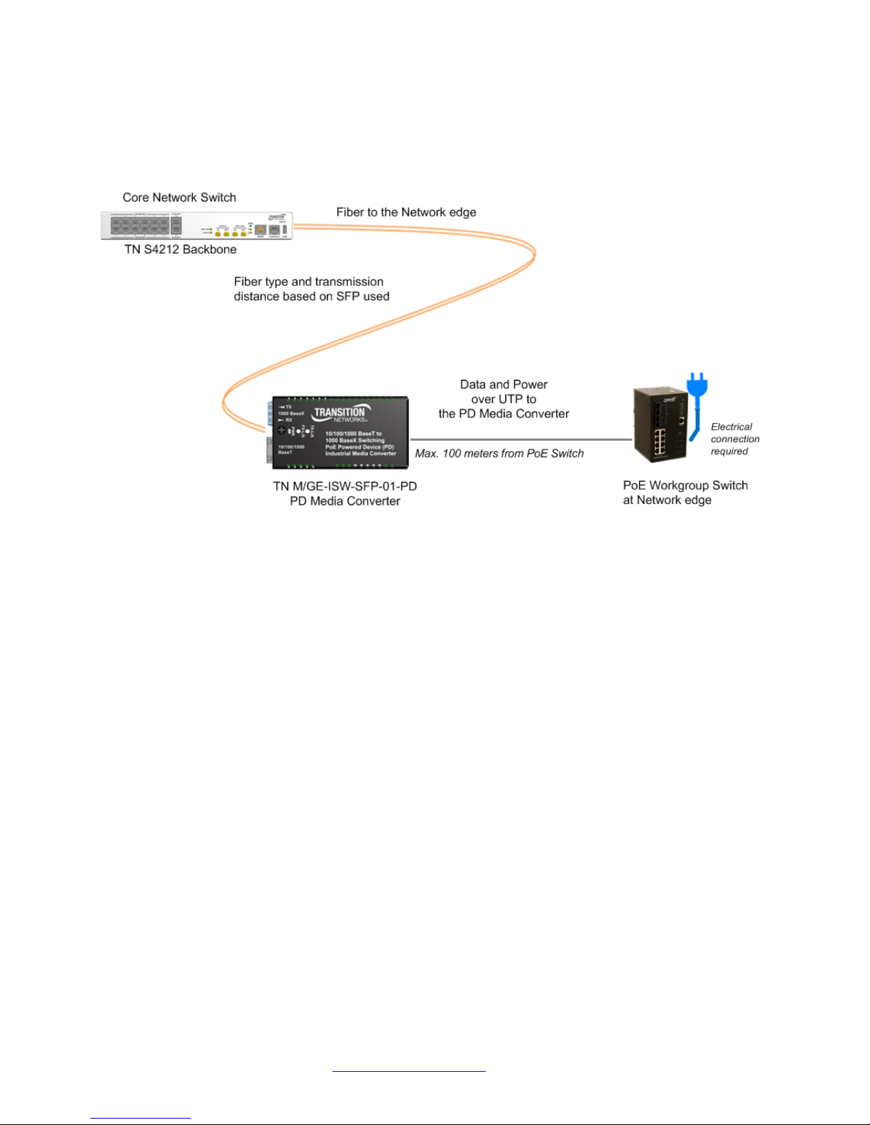
Application Example
The M/GE-ISW-SFP-01-PD is used to operate/maintain a network with data transmit rates to 1G using
Transition Networks products as shown below.
Package Contents
Check that your package contains the following items. Contact your point of purchase if anything is
missing.
□ One M/GE-ISW-SFP-01-PD Hardened Mini PD Media Converter
□ Industrial Velcro Mounting Strip
□ One DIN Rail Clip and screw
□ Documentation Postcard
Save the packing materials for possible future use.
33668 Rev. A http://www.transition.com/ Page 3 of 16
Page 4
Transitio n Networks M/GE-ISW-SFP-01-PD User Guide
Installation
Electrostatic Discharge (ESD) Precautions
Always observe the following ESD precautions when installing or handing the M/GE-ISW-SFP-01-PD:
• Do not remove the converter from its protective packaging until you are ready to install M/GE-ISW-
SFP-01-PD media converter.
• Wear an ESD wrist grounding strap before handling the M/GE-ISW-SFP-01-PD media converter or
any of these component. If you do not have a wrist strap, maintain grounded contact with the unit
throughout any procedure requiring ESD protection.
Installation Opti ons
You can install your media converter using the Industrial Velcro Mounting or the DIN Rail Clips as
described in the following sections.
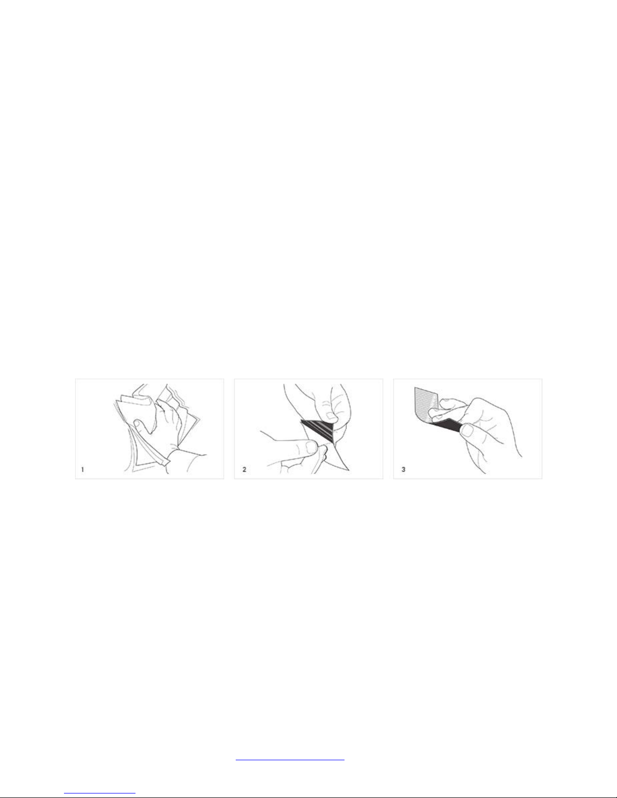
Installing Industrial Velcro
The Industrial Velcrostrip features a molded plastic hook and a heavy-duty, water -resistant adhesive for
superior holding power on smooth sur f ac es, including plastic. It is designed for indoor and outdoor use.
To install the Industrial Velcro onto the media converter:
1. Clean and dry surface before application.
2. Peel tape from fastener and press firmly into place.
3. Adhesive reaches maximum strength after 24 hours.
Note: Recommended for temperatures between 0°F to 150°F. Not recommended for fabrics, dashboards,
flexible vinyl or underwater use. Continued exposure to full sunlight can damage fastener.
May not adhere well to certain types of brick; testing is recommended.
The VELCRO® Brand. © 2015 Velcro Indus tr ies B.V .
33668 Rev. A http://www.transition.com/ Page 4 of 16
Page 5
Transitio n Networks M/GE-ISW-SFP-01-PD User Guide
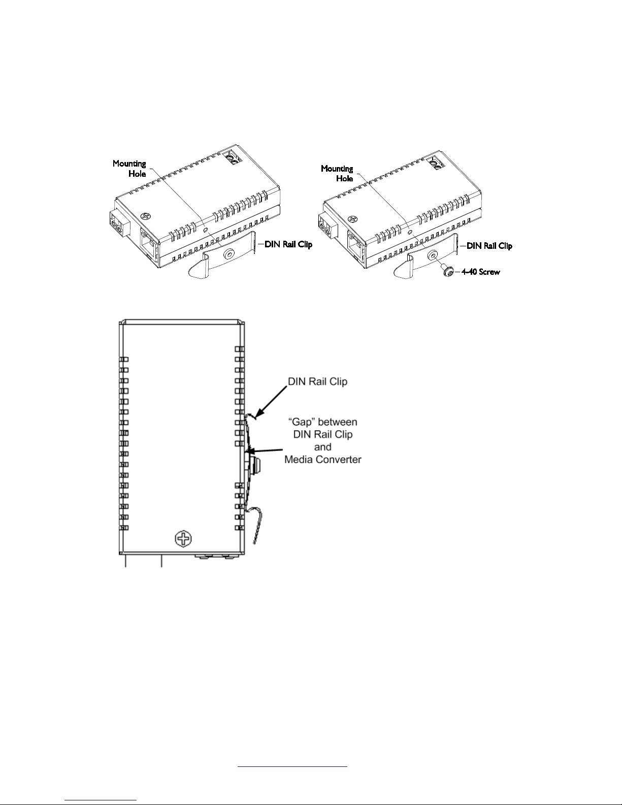
Installing DIN Rail Clip
A DIN Rail Clip and a 4-40 Screw are included. To install the DIN Rail onto the media converter:
1. Position the DIN Rail Clip to the side of the media converter as shown below.
2. Position the 4-40 screw to attach the DIN rail to the media converter as shown above right.
3. Insert and tighten the 4-40 Screw until the DIN Rail Clip appears as shown above. When the DIN Rail
Clip is attached, there should be a “gap” between the Clip and the Media Converter as shown above.
33668 Rev. A http://www.transition.com/ Page 5 of 16
Page 6

Transitio n Networks M/GE-ISW-SFP-01-PD User Guide
Connect Fiber Cables
On the fiber side, full duplex is always on, therefore, the 512-Bit Rule does not apply. The fiber cable
specs are constrained by the type of SFP used.
Connect the Twisted-Pair Copper Cable
The AutoCross feature allows either MDI (straight-through) or MDI-X (crossover) cable connections to be
configured automatically, according to network conditions.
Perform these steps:
1. Locate a 1GbE cable with RJ -45 connectors installed at both ends.
2. Connect the RJ-45 connector at one end of the cable to the RJ-45 port on the M/GE-ISW-SFP01-PD media converter.
3. Connect the RJ-45 connector at the other end of the cable to the RJ-45 port on the other device
(switch, workstation, etc.).
Operation
Status LEDs
Use the status LEDs to monitor M/GE-ISW-SFP-01-PD operation in the network.
PWR: Power status:
On = power is on
Off = power is off
Fiber Link/Act: Fiber port link and activity status:
Green On =1000BASE-X or 100Base-FX fiber link OK
Green Flash = 1000BASE-X or 100Base-FX fiber link OK and activity
Off = Fiber link down
Copper Link/Act: Copper port link and activity status:
Green On =10/100/1000BASE-T copper link OK
Green Flash = 10/100/1000BASE-T copper link OK and activity
Off = Copper link fail
See “Connectors and LEDs” on page 2.
33668 Rev. A http://www.transition.com/ Page 6 of 16
Page 7

Transitio n Networks M/GE-ISW-SFP-01-PD User Guide
SFP module in slot at power up
Fiber port mode after power up
No SFP module
1000BASE-X
1000BASE-X SFP module
1000BASE-X
100BASE-FX SFP module
100BASE-FX
Fiber Port Mode at Power Up
The fiber port mode is defined by the type of SFP module in the SFP slot at power up:
Product Features
The features - Congestion Reduction, Auto-Negotiation, AutoCross™, Active Link Pass-Through,
Automatic link Restoration, Distance Extension, Rate Conversion, and Far End Fault are described
below.
Congestion Reduction
The M/GE-ISW-SFP-01-PD media converters do not forward collision signals or error packets from one
collision domain to another, resulting in improvements in baseline network performance. In addition, the
media converter filters packets destined for local devices, which reduces network congestion.
Auto-Negotiation
The Auto-Negotiation feature is ON permanently for the M/GE-ISW-SFP-01-PD media converters. AutoNegotiation allows the media converter to configure itself automatically to achieve the best possible mode
of operation over a link. It broadcasts speed and duplex capabilities (full or half) to the other device and
negotiates the best mode of operation. Auto-Negotiation allo ws quick and easy installation because the
optimal link is established automatically. In a scenario where an auto-negotiation device is linked to a
non-negotiating device, the negotiating device via parallel detection recognizes the speed of that second
device then establishes the best operating speed at half duplex.
AutoCross™
The AutoCross feature allows using either straight-through (MDI) or crossover (MDI-X) copper cables
when connecting to devices. AutoCross determines the connection characteristics and automatically
configures the device to link up, regardless of the copper cable configuration, MDI or MDI-X.
Active Link Pass-Through (ALPT)
Link Pass-Through is a troubleshooting feature that allows the media converter to monitor both the fiber
and copper RX ports for loss of signal. With the loss of RX signal on one media port, the converter wil l
automatically disable the TX signal of the other media port, thus “passing through” the link loss.
• End device automatically notified of link loss
• Prevents loss of valuable data unknowingly transmitted over invalid link
Active LPT is a form of LPT that requires the links to become Active before LPT becomes Active.
With Active LPT there are 2 states: Diagnostic and Active.
On power-up, the media converter enters the Diagnostic state. In the Diagnostic state, the link for each of
the media converter’s ports can come up independently of each other, just like when regular LPT is
disabled. The Diagnostic state is helpful during first power up, before all links of a circuit are connected,
as it allows the installer to see each link turn on as the cables are plugged in. It’s also helpful for finding
the location of a fault, if one exists.
33668 Rev. A http://www.transition.com/ Page 7 of 16
Page 8

Transitio n Networks M/GE-ISW-SFP-01-PD User Guide
The media converter remains in the Diagnostic state until the following condition is met: the link status for
both of the media converter’s ports is up, simultaneously.
After that condition is met, ALPT enters the Active state. It remains in the Active state until the converter
is powered down. In the Active state, Active LPT works as shown below (the same as when regular LPT
is enabled).
See the ALPT description
on the Transition Networks website for more information.
Automatic Link Restoration
The media converter will autom atic ally re-establish the link when connected to switches if the link is lost.
Distance Extension
The M/GE-ISW-SFP-01-PD media converters can segment one Ethernet and/or Fast Ethernet and one
fiber Fast Ethernet collision domain:
• In a half-duplex Ethernet or Fast Ethernet environment, the M/GE-ISW-SFP-01-PD media
converters extend network distances by segmenting collision domains so that the 512-Bit Rule
applies separately to each collision domain.
• In a full-duplex Ethernet or Fast Ethernet environment, the M/GE-ISW-SFP-01-PD media
converters extend network distances to the physical cable limitations imposed by the selected
twisted-pair copper fiber cables.
Rate Conversion
The M/GE-ISW-SFP-01-PD media converters allow connection of 10Mbps terminal devices on a 10BaseT legacy Ethernet copper network to terminal devices on a 100Mbps Fast Ethernet or 1000Mbps Gigabit
Ethernet copper network and/or terminal devices on a 100Mbps Fast Ethernet or 1000Mbps Gigabit
Ethernet fiber network.
33668 Rev. A http://www.transition.com/ Page 8 of 16
Page 9

Transitio n Networks M/GE-ISW-SFP-01-PD User Guide
Cable and Optic Specifications
The fiber optic cable physical characteristics must meet or exceed IEEE 802.3ae specification.
Fiber Cable
Bit Error Rate: <10-9
Single mode fiber (recommended): 9 μm
Multimode fiber (recommended): 62.5/125 μm
Multimode fiber (optional): 100/140, 85/140, 50/125 μm
Optics
The optics specs depend on the SFP used. See the related SFP documentation for details.
Copper Cable
Category 3: (Minimum requirement for 10 Mbps operation)
Gauge 24 to 22 AWG
Attenuation 11.5 dB/100m @ 5-10 MHz
Maximum Cable Distance 100 meters
Category 5: (Minimum requirement for 100 Mbps operation)
Gauge 24 to 22 AWG
Attenuation 22.0 dB /100m @ 100 MHz
Maximum Cable Distance 100 meters
Category 6: (Minimum requirement for 1 Gbps opera tion)
• Straight-through or crossover twisted-pair cable may be used.
• Shielded (STP) or unshielded (UTP) twisted-pair cable may be used.
• Pins 1&2 and 3&6 are the two active pairs in an Ethernet network.
• Use only dedicated wire pairs for the active pins:
(e.g., blue/white & white/blue, orange/white & white/orange, etc.)
• Do not use flat or silver satin wire.
Category 5e: The category 5e specification improves on the category 5 specification by tightening some
crosstalk specifications and introducing new crosstalk specifications that were not present in the orig inal
category 5 specification. The bandwidth of category 5 and 5e is the same (100 MHz) and the physical
cable construction is the same, and the reality is that most Cat5 cable meets Cat5e specifications, though
it is not tested or certified as such. The cable standard provides performance of up to 100 MHz and is
suitable for 10BASE-T, 100BASE-TX (Fast Ethernet), and 1000BASE-T (Gigabit Ethernet).
10BASE-T and 100BASE-TX Ethernet connections require two wire pairs.
1000BASE-T Ethernet connections require four wire pairs. Cat 5e is the minimum for 1000 Mbps.
Category 6 cable, commonly referred to as Cat 6, is a standardized cable for Gigabit Ethernet and other
network physical layers that is backward compatible with the Category 5/5e and Category 3 cable
standards. Compared to Cat 5 and Cat 5e, Cat 6 provides more stringent specifications for crosstalk and
system noise. The Cat 6 cable standard provides performance of up to 250 MHz and is suitable for
33668 Rev. A http://www.transition.com/ Page 9 of 16
Page 10

Transitio n Networks M/GE-ISW-SFP-01-PD User Guide
10BASE-T, 100BASE-TX (Fast Ethernet), 1000BASE-T/1000BASE-TX (Gigabit Ethernet) and 10GBASET (10-Gigabit Ethernet) . Category 6 cable has a reduced maximum length when used for 10GBASE-T.
Like most of the earlier twisted-pair cables, Category 6 cable contains four twisted wire pairs. Attenuation,
Near End crosstalk (NEXT), and PSNEXT (Power Sum NEXT) in Cat 6 cable and connectors are all
much lower than Cat 5 or Cat 5e, which uses 24 AWG wire. The increase in performance with Cat 6
comes mainly from increased (22 AWG) wire size. Because the conductor sizes are generally the same,
Cat 6 jacks may also be used with Cat 5e cable.
Category 6 cable can be identified by the printing on the side of the cable sheath. Cat 6 patch cables are
normally terminated in 8P8C modular connectors. If Cat 6 rated patch cables, jacks, and connectors are
not used with Cat 6 wiring, overall performance is degraded to that of the cable or connector.
Connectors use either T568A or T568B pin assignments; although performance is comparable provided
both ends of a cable are the same, T568B is a deprecated standard in the US and no longer supported by
TIA.
Category 6a cable, or Augmented Category 6, is characterized to 500 MHz and has improved alien
crosstalk characteristics, allowing 10GBASE-T to be run for the same distance as previous protocols.
The latest standard from the TIA for enhanced performance standards for twisted pair cable systems was
defined in February 2008 in ANSI/TIA/EIA-568-B.2-10. Category 6a is defined at frequencies up to 500
MHz - twice that of Cat. 6. Category 6a performs at improved specifications, in particular in the area of
alien crosstalk, as compared to Cat 6 UTP (unshielded twisted pair), which exhibited high alien noise in
high frequencies.
The global cabling standard ISO/IEC 11801 has been extended by the addition of amendment 2, which
defines new specifications for Cat 6a components and Class EA permanent links. These new global Cat
6a/Class EA specifications require a new generation of connecting hardware, which offer superior
performance compared to existing products based on the American TIA standard.
Note the performance difference between ISO/IEC and EIA/TIA component specifications for the NEXT
transmission parameter. At a frequency of 500 MHz, an ISO/IEC Cat 6a connector performs 3 dB better
than a Cat 6a connector that conforms to the EIA/TIA specification. The 3 dB represents a 100% increase
of near-end crosstalk noise reduction when measured in absolute magnitudes.
Maximum Length
When used for 10/100/1000BASE-T, the maximum allowed length of a Cat 6 cable is 100 meters or 328
feet. This consists of 90 meters (300 ft) of solid "horizontal" cabling between the patch panel and the wall
jack, plus 10 meters (33 ft) of stranded patch cable between each jack and the attached device. Since
stranded cable has higher attenuation than solid cable, exceeding 10 meters of patch cabling will reduce
the permissible length of horizontal cable.
When used for 10GBASE-T, Cat 6 cable's maximum length is 55 meters (180 ft) in a favorable alien
crosstalk environment, but only 37 meters (121 ft) in a hostile alien crosstalk environment, such as when
many cables are bundled together. However, because the effects of alien crosstalk environments on
cables are difficult to determine prior to installation, it is highly recommended that all Cat 6 cables being
used for 10GBASE-T are electrically tested once installed. With its improved specifications, Cat6 A does
not have this limitation and can run 10GBASE-T at 100 meters (330 ft) without electronic testing.
Installation Notes
Category 6 and 6a cable must be properly installed and terminated to meet specifications. The cable
must not be kinked or bent too tightly (the bend radius should be at least four times the outer diameter of
the cable). The wire pairs must not be untwisted and the outer jacket must not be stripped back more
than 1/2 inch (1.27 cm). All shielded cables must be grounded for safety and effectiveness and a
continuous shield connection maintained from end to end. Ground loops develop when there is more than
one ground connection and the difference in common mode voltage potential at these ground
connections introduces noise into the cabling. Note that 23 or 24 AWG wire is allowed if the ANSI/TIA568-B.2-1 performance specifications are met. The figure below shows the pins on plug face; note that
the socket is the reverse of the plug pinout shown below. For more information, see the TIA web site or
the IEEE web site.
33668 Rev. A http://www.transition.com/ Page 10 of 16
Page 11

Transitio n Networks M/GE-ISW-SFP-01-PD User Guide
Standards Compliance
IEEE 802.3-2012
Regulatory Compliance for Emission
EN55022 Class A
Regulatory Compliance for Immunity
EN55024
Safety Compliance
NA
Power Consumption
1.8W (47mA @ 37V PoE input)
Power Source
IEEE 802.3af supplied through TP RJ-45
Size (width x depth x height)
3.3 “ x 1.8 ” x 0.8 ” (83.82 x 45.72 x 20.32 mm)
Weight
0.25 lb. (0.11 Kg.)
Operating Temperature
-40 to +75 deg. C
Storage Temperature
-40 to + 85 deg. C
Altitude
0-10,000 feet
Operating Humidity
5% to 95% (non-condensing)
Greater than 225,000 MIL-HDBK-217F Hours.
Environment: GB, Ground Benign. Temperature 25°C.
Warranty
Lifetime
Troubleshooting Cat 6 & Cat 6a Structured Copper Cabling Systems
If a Category 6 cabling system does not meet the electrical requirements for supporting 10GBASE-T
applications, see the TSB-155 provides guidelines designed to mitigate the alien crosstalk between the
target pair and the disturbing pairs of Category 6 channels and permanent links. Annex B of TSB-155
outlines the following mitigation actions most appropriate for individual situations:
• Use Category 6 shielded or Category 6a patch cords;
• Replace Category 6 connectors with Category 6a connectors;
• Use non-adjacent patch panel positions;
• Separate equipment cords and patch cords;
• Unbundle or more loosely bundle the horizontal cabling; and
• Reconfigure the cross-connect as an interconnect.
Technical Specifications
The Transition Networks M/GE-ISW-SFP-01-PD was designed to meet these specifications.
MTBF*
CAUTION: Copper based media ports, e.g., Twisted Pair (TP) Ethernet, USB, RS232, RS422, RS485,
DS1, DS3, Video Coax, etc., are intended to be connected to intrabuilding (inside plant) link segments
that are not subject to lightening transients or power faults . Copper-based media ports are NOT to be
connected to interbuilding (outside plant) link segments that are subject to lightening transients or power
faults. Failure to observe this caution could result in damage to equipment.
WARNING: Visible and invisible laser radiation when open. Do not stare into the beam or view directly
with optical instruments. Failure to observe this warning could result in an eye injury or blindness.
WARNING: Use of controls, adjustments, or the performance of procedures other than those specified
herein could result in hazardous radiation exposure.
The information in this manual is subject to change. For the most up-to-date information, view the user’s
guide on-line at www.transition.com
33668 Rev. A http://www.transition.com/ Page 11 of 16
Greater than 618,750 Bellcore Hours.
Prediction Method: MIL-HDBK-217F Parts Count.
and the click on Product/Product Finder.
Page 12

Transitio n Networks M/GE-ISW-SFP-01-PD User Guide
Property
802.3af (802.3at Type 1)
802.3at Type 2
Power available at PD
12.95 W
25.50 W
Maximum power
delivered by PSE
15.40 W
30.0 W
Voltage range (at PSE)
44.0–57.0 V
50.0–57.0 V
Voltage range (at PD)
37.0–57.0 V
42.5–57.0 V
Maximum current
350 mA
600 mA per mode
Maximum cable
resistance
20 Ω (
12.5 Ω (
Three power class levels
negotiated at initial connect ion
Four power class levels negotiated at initial
connection or 0.1 W steps negotiated
continuously
Derating of maximum
temperature
None
5°C with one mode (two pairs) active
Supported cabling
Category 3 and Category 5
[1]
Category 5
Mode A (endspan), Mode B
(midspan)
Mode A, Mode B
PoE Standards and Power Classifications
The original IEEE 802.3af-2003 PoE standard provides up to 15.4 W of DC power (minimum 44 V DC
and 350 mA) to each device.
The updated IEEE 802.3at-2009 PoE standard also known as PoE+ or PoE plus, provides up to 25.5 W
of power. The 2009 standard prohibits a powered device from using all four pairs for power.
Both of these amendments have since been incorporated into the IEEE 802.3-2012 publication.
Standard PoE Parameters Comparison (Wikipedia)
Category 3)
Power management
cable ambient operating
Supported modes
Note: More stringent cable specification allows assumption of more current carrying capacity and lower
resistance (20.0 Ohms for Category 3 versus 12.5 Ohms for Category 5).
Category 5)
33668 Rev. A http://www.transition.com/ Page 12 of 16
Page 13

Transitio n Networks M/GE-ISW-SFP-01-PD User Guide
Troubleshooting
If the media converter fails, isolate and correct the fault by determining the answers to the following
questions and then taking the indicated action:
1. Is the PWR (power on) LED lit?
NO
• Is the RJ-45 wired to an IEEE 802.3af or 802.3at PSE product powered and enabled?
• Contact Tech Support. See Contact Us on page 14.
YES
• Proceed to step 2.
2. Is the TX-L/A (copper link) LED lit?
NO
• Check the twisted-pair copper cables for proper connection. See Connect the Twisted-Pair
Copper Cable on page 6.
• Contact Tech Support. See Contact Us on page 14.
YES
• Proceed to step 3.
3. Is the FX-L/A (fiber link) LED lit?
NO
• Check the fiber cables for proper connection. See Connect Fiber Cables on pag e 6.
• Verify that the fiber cables on the media converter are properly connected to the ports on the
other device.
• Verify the correct SFP is used; reseat the SFP and re-power the device to ensure the SFP
s peed was reg ister ed. Se e “ Fiber Port Mode at Power Up” on page 7.
• Contact Tech Support. See Contact Us on page 14.
YES
• Proceed to step 4.
4. Is the TX (copper receive) LED flashing?
NO
• If there is activity on the copper port, disconnect and reconnect the copper cable to reinitialize.
• Restart the workstation to restart the initialization process.
• Contact Tech Support. See Contact Us on page 14.
YES
• Contact Tech Support. See Contact Us on page 14.
5. Check for a duplex mode / auto-negotiation mode mismatch.
6. Make sure the Ethernet link established is not too long for effective PoE delivery.
7. Try the Ethernet switch cable diagnostics feature.
8. Check cable type (Cat 5/5e/6; single- or multi-strand), mechanical connectors, electrical noise in cable.
9. Check if nonpowered Ethernet devices can establish an Ethernet link on a port.
10. Verify that PoE and Non-PoE devices do not work on this port but work on other ports.
11. Check if the problem happens at a specific time of day or night.
12. If the problem started after the PD was working, check what changed (e.g., any hardware or software
changes).
33668 Rev. A http://www.transition.com/ Page 13 of 16
Page 14

Transitio n Networks M/GE-ISW-SFP-01-PD User Guide
Contact Us
Technical support
Technical support is available 24-hours a day
US and Canada: 1-800-260-1312
International: 00-1-952-941-7600
Transition now
Chat live via the Web with Transition Networks Technical Support.
Log onto www.transition.com
Web-based seminars
Transition Networks provides seminars via live web-based training.
Log onto www.transition.com
E-Mail
Ask a question anytime by sending an e-mail to our technical support staff.
techsupport@transition.com
Address
Transition Networks
10900 Red Circle Drive
Minnetonka, MN 55343, U.S.A.
telephone: 952-941-7600
toll free: 800-526-9267
fax: 952-941-2322
and click the Transition Now link.
and click the Learning Center link.
33668 Rev. A http://www.transition.com/ Page 14 of 16
Page 15

Transitio n Networks M/GE-ISW-SFP-01-PD User Guide
Compliance Information
Declaration of Conformity
FCC regulations
This equipment has been tested and found to comply with the limits for a Class A digital device, pursuant
to Part 15 of the FCC rules. These limits are designed to provide reasonable protection against harmful
interference when the equipment is operated in a commercial environment. This equipment generates,
uses, and can radiate radio frequency energy and, if not installed and used in accordance with the
instruction manual, may cause harmful interference to radio communications. Operation of this equipment
in a residential area is likely to cause harmful interference, in which case the user will be required to
correct the interference at the user's own expense.
Canadian regulations
This digital apparatus does not exceed the Class A limits for radio noise for digital apparatus set out on
the radio interference regulations of the Canadian Department of Communications.
Le présent appareil numérique n'émet pas de bruits radioélectriques dépassant les limites applicables
aux appareils numériques de la Class A prescrites dans le Règlement sur le brouillage radioélectrique
édicté par le ministère des Communications du Canada.
33668 Rev. A http://www.transition.com/ Page 15 of 16
Page 16

Transitio n Networks M/GE-ISW-SFP-01-PD User Guide
Rev
Date
Notes
A
1/20/16
Initial release.
European regulations
Warning
This is a Class A product. In a domestic environment this product may cause radio interference in which
case the user may be required to take adequate measures.
Achtung !
Dieses ist ein Gerät der Funkstörgrenzwertklasse A. In Wohnbereichen können bei Betrieb dieses
Gerätes Rundfunkstörungen auftreten. In diesem Fäll is der Benutzer für Gegenmaßnahmen
verantwortlich.
Attention !
Ceci est un produit de Classe A. Dans un environment domestique, ce produit risque de créer des
interférences radioélectriques, il appartiendra alors à l'utilsateur de prende les measures spécifiques
appropriées.
In accordance with European Union Directive 2002/96/EC of the European Parliament and
of the Council of 27 January 2003, Transition Networks will accept post usage returns of
this product for proper disposal. The contact information for this activity can be found in the
'Contact Us' portion of this docum ent.
CAUTION: RJ connectors are NOT INTENDED FOR CONNECTION TO THE PUBLIC
TELEPHONE NETWORK. Failure to observe this caution could result in damage to the
public telephone network.
Der Anschluss dieses Gerätes an ein öffentlickes Telekommunikationsnetz in den
EGMitgliedstaaten verstösst gegen die jeweligen einzelstaatlichen Gesetze zur Anwendung der Richtlinie
91/263/EWG zur Angleichung der Rechtsvorschriften der Mitgliedstaaten über
Telekommunikations end ei n ric htung en ei ns chli es slich der gegenseitigen Anerkennung ihrer Konformität.
Record of Revisions
Trademarks
All trademarks and registered trademarks are the property of their respective owners.
Copyright restrictions
© 2015-16 Transition Networks. All rights reserved. No part of this work may be reproduced or used in any form or by
any means - graphic, electronic or mechanical - without written permission from Transition Networks.
33668 Rev. A http://www.transition.com/ Page 16 of 16
 Loading...