

Page 1

10BASE-FL CABLE SPECIFICATIONS
10BASE-FL Cable Characteristics:
MULTIMODE
Fiber Optic Cable Recommended: 62.5 / 125 µm multimode fiber
Optional: 100 / 140 µm multimode fiber
85 / 125 µm multimode fiber
50 / 125 µm multimode fiber
Fiber Optic Transmitter Power: Average: -15 dBm
Fiber Optic Receiver Sensitivity: Average : -33 dBm
Wavelength: 850nM
Bit error rate: ≤10
-10
Maximum Cable Distance: 2 kilometers (6,600 feet)
10BASE-FL Connector Characteristics:
ST type connectors
16
CAUTION: RJ connectors are NOT INTENDED FOR
CONNECTION TO THE PUBLIC TELEPHONE
NETWORK. Failure to observe this caution could result
in damage to the public telephone network.
Compliance Information
UL Listed
C-UL Listed (Canada)
CISPR/EN60950 Class A
FCC Regulations
This equipment has been tested and found to comply with the limits for a class
A digital device, pursuant to part 15 of the FCC rules. These limits are
designed to provide reasonable protection against harmful interference when
the equipment is operated in a commercial environment. This equipment
generates, uses, and can radiate radio frequency energy and, if not installed
and used in accordance with the instruction manual, may cause harmful
interference to radio communications. Operation of this equipment in a
residential area is likely to cause harmful interference, in which case the user
will be required to correct the interference at the user’s own expense.
Canadian Regulations
This digital apparatus does not exceed the Class A limits for radio noise for
digital apparatus set out on the radio interference regulations of the Canadian
Department of Communications.
European Regulations
Warning
This is a Class A product. In a domestic environment this product may cause
radio interference in which case the user may be required to take adequate
measures.
Copyright Restrictions
© 1998 TRANSITION Networks.
All rights reserved. No part of this work may be reproduced or used in any
form or by any means – graphic, electronic, or mechanical – without written
permission from TRANSITION Networks.
Trademark Notice
All registered trademarks and trademarks are the property of their respective
owners.
Der Anschluss dieses Gerätes an ein öffentlickes
Telekommunikationsnetz in den EG-Mitgliedstaaten verstösst gegen die
jeweligen einzelstaatlichen Gesetze zur Anwendung der Richtlinie
91/263/EWG zur Angleichung der Rechtsvorschriften der
Mitgliedstaaten über Telekommunikationsendeinrichtungen
einschliesslich der gegenseitigen Anerkennung ihrer Konformität.
Page 2
14
1
1. INTRODUCTION
This guide is intended for the system or network administrator
responsible for installing and monitoring a TRANSITION Networks
LANMaster™ T8-FL 8-Port Ethernet™ Repeater Hub. A working
knowledge of local area network (LAN) operations, including
familiarity with communications protocols used on interconnected
LANs, is assumed.
The LANMaster T8-FL
The TRANSITION Networks LANMaster T8-FL 8-Port Ethernet
Repeater Hub is a 10 Mb/s network device with eight (8) 10BASE-T
connectors at the front of the hub and one (1) 10BASE-FL-compliant
duplex ST connector set at the back of the hub.
Features:
• Eight fixed RJ-45 twisted-pair connectors at front provide
terminal device connections
• Optional RJ-45 uplink port connector at front eliminates need
for crossover cable between hubs
• 10BASE-FL-compliant duplex ST connectors at back provides
optional connection to 10BASE-FL fiber backbone or to any
10BASE-FL-compliant device
• LED indicators at front monitor LANMaster T8-FL network
traffic
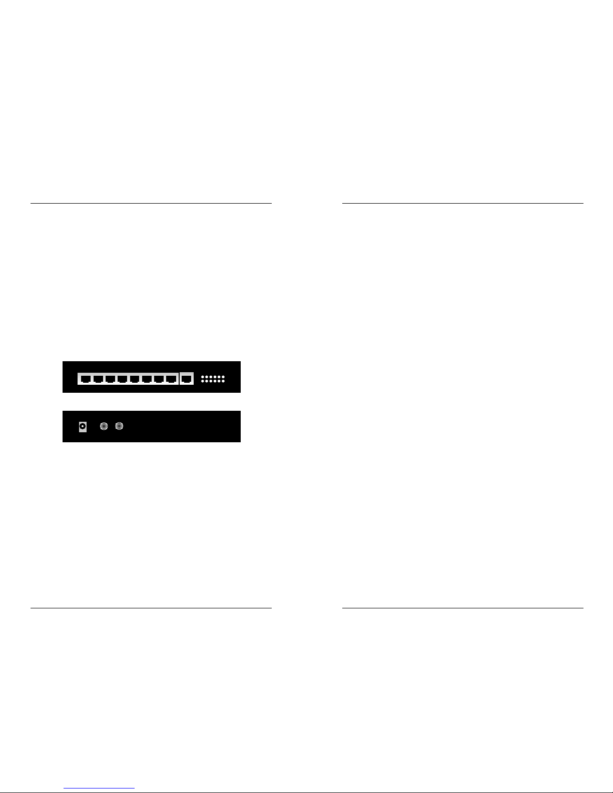
1X 2X 3X 4X 5X 6X 7X 8X 8I
LANMaster T8 Front
5 6 7 8 TX Collision
1 2 3 4 FL Power
Link/RX
10BASE-T PORTS
LANMaster T8 Back
RX
TX
Fiber
The sole purpose of this remedy shall be provided the customer with the replacement or
repair of non-conforming goods in the manner described in this Warranty statement. This
exclusive remedy shall not be deemed to have failed of its essential purpose so long as TN is
willing and able to repair or replace the defective item(s) or refund the purchase price.
TN reserves the right to inspect products claimed to be defective under warranty either at the
customer’s location or at TN’s plant. TN assumes no liability for liability charges incidental
to the adjustment, service, repairing, removal or replacement of the product, or other costs,
or the expense of repairs made outside of its factory, except when made with TN’s prior
written consent. Additionally, Transition Networks reserves the right to charge for all testing
and shipping incurred, if after testing, a return is classified as “No Problem Found”.
TN’s total liability in connection with the products and their installation to all persons and
from all causes in the aggregate, whether in contract, tort, or strict liability, shall not exceed
the amount paid to TN for the product directly related to the alleged damage. However, in
no event shall TN have any liability to a customer or any third party for products
manufactures according to the customer’s specifications.
C. Return Procedure
The customer must follow this procedure for the return of defective items:
1. Locate the serial number(s) of the item(s) to be returned.
2. Determine the date the item(s) was received.
3. Contact Transition Networks Technical Support to determine if the problem can be
corrected on site.
If not, and the product is covered by warranty, then:
• Call the distributor directly or contact TN.
• Request a Return Material Authorization (RMA).
• Ship the item, prepaid in original packaging to Transition Networks at the above
address.
• Include the RMA number on the outside of the carton and/or on the Packing List.
• Include a copy of the RMA form.
• Include a copy of the original invoice or packing list (if possible) to expedite
processing.
• The item(s) may be shipped by the customer or the distributor.
• Transition Networks will repair or replace the unit, at TN’s discretion, and cover the
cost of the return freight to the distributor or to the customer, whichever requested
the RMA number.
If the item(s) was received more than five years ago, or if the item(s) is no longer covered by
warranty for other reasons, then:
• Call the distributor or contact TN.
• Request a Material Repair Authorization number (MRA).
• Ship the item(s), prepaid, in the original packaging to Transition Networks at the
above address.
• Include the MRA number on the outside of the carton add/or on the Packing List.
• Include a copy of the MRA form.
• Include a copy of the original invoice or packing list (if possible) to expedite processing.
• Only the customer (end-user) may send the items(s) to TN.
• TN will contact the customer after the item(s) have been received, inspected, and a
cost estimate of the repair determined.
• The repair charges may be billed, with customer’s approval, though the distributor, or
on a prepaid or C.O.D. basis directly to the customer. The charges will include the
cost of shipping.
The return authorization numbers are valid only for 90 days from the date issued.
Page 3

12
3
Connectors and Indicators
CONNECTORS
Eight (8) straight-through RJ-45 connectors, labeled 1X-8X, and one
(1) crossover RJ-45 connector, labeled 8I, are located on the front of
the LANMaster T8-FL.
One (1) TX and one (1) RX fiber ST connector and one (1) AC power
supply adapter connector are located at the LANMaster T8-FL back.
LED INDICATORS
Steady green Link/RX LEDs indicate (for each port 1-8) the integrity
of the network link at the RJ-45 connector. Blinking green Link/RX
LEDs indicate (for each port) reception of valid data.
Steady green FL LED indicates the integrity of the network link at the
fiber receive (RX) connector. Blinking green FL LED indicates
reception of valid data.
Blinking green TX LED
indicates transmission of
valid data at the fiber transmit
(TX) connector.
Steady green Power LED
indicates connection of the
LANMaster T8-FL to external AC power.
Blinking yellow Collision LED indicate network collisions.
5. MAINTENANCE
WARNING: DO NOT, UNDER ANY CIRCUMSTANCES, open
and attempt to repair the LANMaster T8-FL. Failure to observe
this warning could result in personal injury or death from
electrical shock.
NOTE: Failure to observe the above warning will immediately void the
warranty.
Fault Isolation
If two network devices fail to communicate through the LANMaster T8FL, consider the following:
• Are the LEDs described in the previous section functioning
properly?
• Do network devices have Link Integrity enabled?
• Do network devices communicate when the LANMaster T8-FL
is not installed between them?
• Is flat or “silver satin” wire used in site internal wiring?
• Are internal wiring patch cords, punch down blocks, and wall
jacks properly pinned or configured?
• Are network interface cards properly configured?
• Are network cables and connectors properly installed?
Technical Support Contact
For assistance in fault isolation and in maintaining the LANMaster T8FL, contact:
Technical Support (800) 260-1312
or your local distributor.
Power Adapter Connector
Fiber TX and RX ST Connectors
RX
TX
Fiber
1X 2X 3X 4X 5X 6X 7X 8X 8I
5 6 7 8 TX Collision
1 2 3 4 FL Power
Link/RX
10BASE-T PORTS
Straight-through RJ-45 Connectors
Crossover RJ-45 (8I) Connector
5 6 7 8 TX Collision
1 2 3 4 FL Power
Link/RX
Page 4

10
5
Powering the LANMaster T8-FL
To power ON the LANMaster T8-FL:
1. Verify that the LANMaster T8-FL power supply adapter is the
correct power supply adapter for the site installation.
2. At LANMaster T8-FL back, locate the power receptacle.
3. Connect the LANMaster T8-FL power connector end of the
power supply adapter to the LANMaster T8-FL power
receptacle.
4. Plug external power connector end (male) of the power
supply adapter into correct voltage AC wall socket.
5. At LANMaster T8-FL front, verify that Power LED is
illuminated.
3. INSTALLATION
To install the LANMaster T8-FL:
• Unpack the LANMaster T8-FL
• Install LANMaster T8-FL at site
• Install Network Cable
• Power the LANMaster T8-FL.
Direction is provided in the pages that follow.
Unpacking the LANMaster T8-FL
The LANMaster T8-FL packing contents should include the following:
Item Part Number
LANMaster T8-FL Hub E-TBT-HB-0810
(includes mounting brackets and screws)
Power Supply Adapter 3542, 3543, 3544, or 3545
(depending upon power configuration
in country where installed)
User’s Guide 33038
Page 5

8
7
Installing Network Cable
10BASE-T Cable Connection Requirements
STRAIGHT-THROUGH/CROSSOVER CABLE/CONNECTOR
NOTE: The 10BASE-T cable and RJ-45 jacks for hub-to-terminal device
connections must be configured as straight-through. The 10BASE-T
cable and RJ-45 jacks for hub-to-hub connections must be configured
as crossover. The “8I” port provided on the LANMaster T8-FL front
changes a physical straight-through configuration cable to a logical
crossover configuration cable for hub-to-hub connections.
Ensure that all 10BASE-T cable to be installed is configured as straightthrough:
FIVE-SEGMENT RULE
10BASE-T cable segments can be installed as a single Ethernet collision
domain if the cable segments are connected using repeaters. (A
segment is the independent network cable connection between
repeaters or between repeaters and network devices.)
When connecting LANMaster T8-FL repeater hubs, the transmission
path between any two network devices can consist of no more than
five segments.
RJ-45 PLUG
18234
5
6
7
RJ-45 JACK
1
8
To verify the network configuration by assigning segment numbers to
cable connections:
1. Determine the two terminal devices in the network which are
separated by the greatest number of segments.
2. Assign a segment path between the terminal devices by
labeling the cable connected to one of the terminal devices
“segment 1” and the segment connected to the other terminal
device “segment n” (n = total number of segments ≤ 5).
3. To verify that no segment paths contain more than n segments,
assign segment paths and numbers to all other terminal
devices.
5
3
2
3
4
10BASE-T PORTS
1X 2X 3X 4X 5X 6X 7X 8X 8I
Link/Rx
1234
5678
FLPower
TXCollision
10BASE-T PORTS
1X 2X 3X 4X 5X 6X 7X 8X 8I
Link/Rx
1234
5678
FLPower
TXCollision
10BASE-T PORTS
1X 2X 3X 4X 5X 6X 7X 8X 8I
Link/Rx
1234
5678
FLPower
TXCollision
1
10BASE-T PORTS
1X 2X 3X 4X 5X 6X 7X 8X 8I
Link/Rx
1234
5678
FLPower
TXCollision
4
The two active pairs in a
10BASE-T network are pins 1
& 2 and pins 3 & 6. Use only
dedicated wire pairs (such as
blue/white & white/blue,
orange/white & white/orange)
for the active pins.
Straight Through Cable
at RJ-45 Plug
Hub . . . . . . . . . . . . . . . .PC, transceiver, NIC, printer
RJ-45 Male . . . . . . . . . . . . . . .RJ-45 Male
1 . . . . . . . . . . . . . . . . . . .1
2 . . . . . . . . . . . . . . . . . .2
3 . . . . . . . . . . . . . . . . . .3
6 . . . . . . . . . . . . . . . . . . .6
 Loading...