

Page 1
MEDIA CONVERTER TECHNICAL SPECIFICATIONS
Standards IEEE 802.3
Case dimensions 17.0" x 7.5" x 1.7" (432mm x 191mm x 43mm)
Environment Temperature: 0-50°C (32° to 122° F )
Humidity 10-90%, non condensing
Altitude 0-10,000 feet
Warranty 2 years
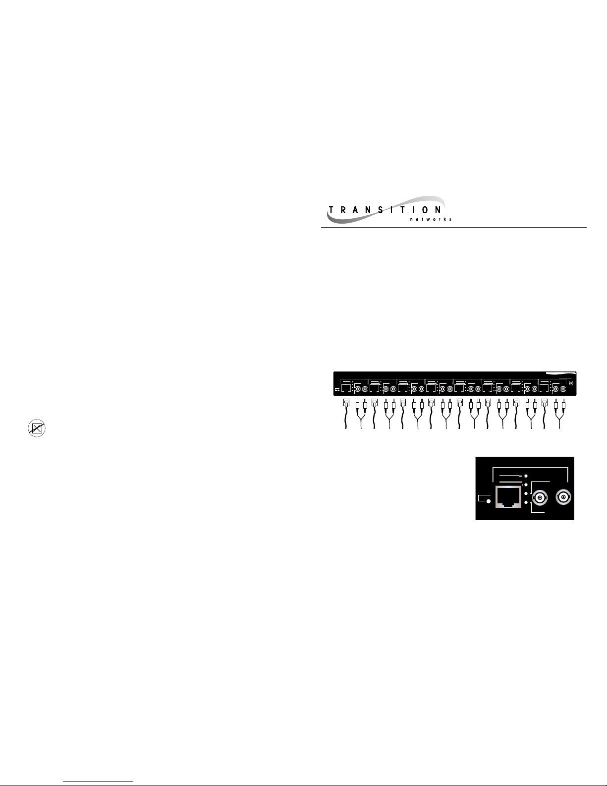
The 8-Port 10BASE-T to Fiber Media Converter provides eight (8) separate
and independent 10BASE-T to fiber media converters in a convenient
19-inch rack mountable chassis. NOTE: The media converter supports
10Mb/s speeds only.
8-Port 10BASE-T to Fiber
Media Converter
E-TBT-FRL-1007
USER’S GUIDE
Minneapolis, MN 55344 USA
CAUTION: RJ connectors are NOT INTENDED FOR CONNECTION TO THE PUBLIC
TELEPHONE NETWORK. Failure to observe this caution could result in damage to the
public telephone network.
Compliance Information
UL Listed
C-UL Listed (Canada)
CISPR/EN55022 Class A
FCC Regulations
This equipment has been tested and found to comply with the limits for a class A digital device, pursuant to part 15 of
the FCC rules. These limits are designed to provide reasonable protection against harmful interference when the
equipment is operated in a commercial environment. This equipment generates, uses, and can radiate radio
frequency energy and, if not installed and used in accordance with the instruction manual, may cause harmful
interference to radio communications. Operation of this equipment in a residential area is likely to cause harmful
interference, in which case the user will be required to correct the interference at the user’s own expense.
Canadian Regulations
This digital apparatus does not exceed the Class A limits for radio noise for digital apparatus set out on the radio
interference regulations of the Canadian Department of Communications.
European Regulations
Warning
This is a Class A product. In a domestic environment this product may cause radio interference in which case the user
may be required to take adequate measures.
Copyright Restrictions
© 1996 TRANSITION Networks Inc. All rights reserved. No part of this work may be reproduced or used in any form
or by any means – graphic, electronic, or mechanical – without written permission from TRANSITION Networks Inc.
Trademark Notice
Der Anschluss dieses Gerätes an ein öffentlickes Telekommunikationsnetz in den EG-Mitgliedstaaten verstösst
gegen die jeweligen einzelstaatlichen Gesetze zur Anwendung der Richtlinie 91/263/EWG zur Angleichung der
Rechtsvorschriften der Mitgliedstaaten über Telekommunikationsendeinrichtungen einschliesslich der
gegenseitigen Anerkennung ihrer Konformität.
RX
10BaseT
TX
RJ RX
Power
RJ Link
FL Link
FL RX
Converter 1
RX
10BaseT
TX
RJ RX
RJ Link
FL Link
FL RX
RX
10BaseT
TX
RJ RX
RJ Link
FL Link
FL RX
RX
10BaseT
TX
RJ RX
RJ Link
FL Link
FL RX
RX
10BaseT
TX
RJ RX
RJ Link
FL Link
FL RX
RX
10BaseT
TX
RJ RX
RJ Link
FL Link
FL RX
RX
10BaseT
TX
RJ RX
RJ Link
FL Link
FL RX
RX
10BaseT
TX
RJ RX
RJ Link
FL Link
FL RX
Converter 2 Converter 3 Converter 4 Converter 5 Converter 6 Converter 7 Converter 8
Transition Networks 8 Port 10BaseT to Fiber Media Converter
(1-8)
INDICATORS
(RJ, FL) Link Steady green LED
indicates port is
receiving link
signal.
(RJ, FL) RX Flashing green
LED indicates
port is receiving
data.
Power Steady green LED indicates 8-Port 10BASE-T to
Fiber Media Converter is powered by AC current.
CONNECTORS
10BASE-T RJ-45 connector
10BASE-FL TX, RX ST type connectors (SMA type available
upon request)
Power Female 3-prong AC connector
10BASE-FL CABLE SPECIFICATIONS
Fiber Optic Cable Recommended: 62.5 / 125 µm multimode fiber
Optional: 100 / 140 µm multimode fiber
85 / 125 µm multimode fiber
50 / 125 µm multimode fiber
Fiber Optic Transmitter Power: Average power: -15.0 dBm
Peak power: -12.0 dBm ±1dBm
Fiber Optic Receiver Sensitivity: Average sensitivity: -27.4 dBm
Bit error rate: ≤10
-10
Maximum Cable Distance: 2000 meters (6500 feet)
10BASE-T CABLE SPECIFICATIONS
Required: Category 3; Recommended: Category 5 wire. Use either shielded twisted
pair (STP) or unshielded twisted pair (UTP). DO NOT USE FLAT/SILVER SATIN WIRE.
Category 3:
Gauge 24 to 22 AWG
Attenuation 28 dB/1000’ @ 10 MHz
Differential Characteristic Impedance 100 Ω ±10% @ 10 MHz
Category 5:
Gauge 24 to 22 AWG
Attenuation 20 dB/1000’ @ 10 MHz
Differential Characteristic Impedance 100 Ω ±10% @ 10 MHz
Maximum Cable Distance: 100 meters (330 feet)
RX
10BaseT
TX
RJ RX
Power
RJ Link
FL Link
FL RX
Converter 1
Page 2
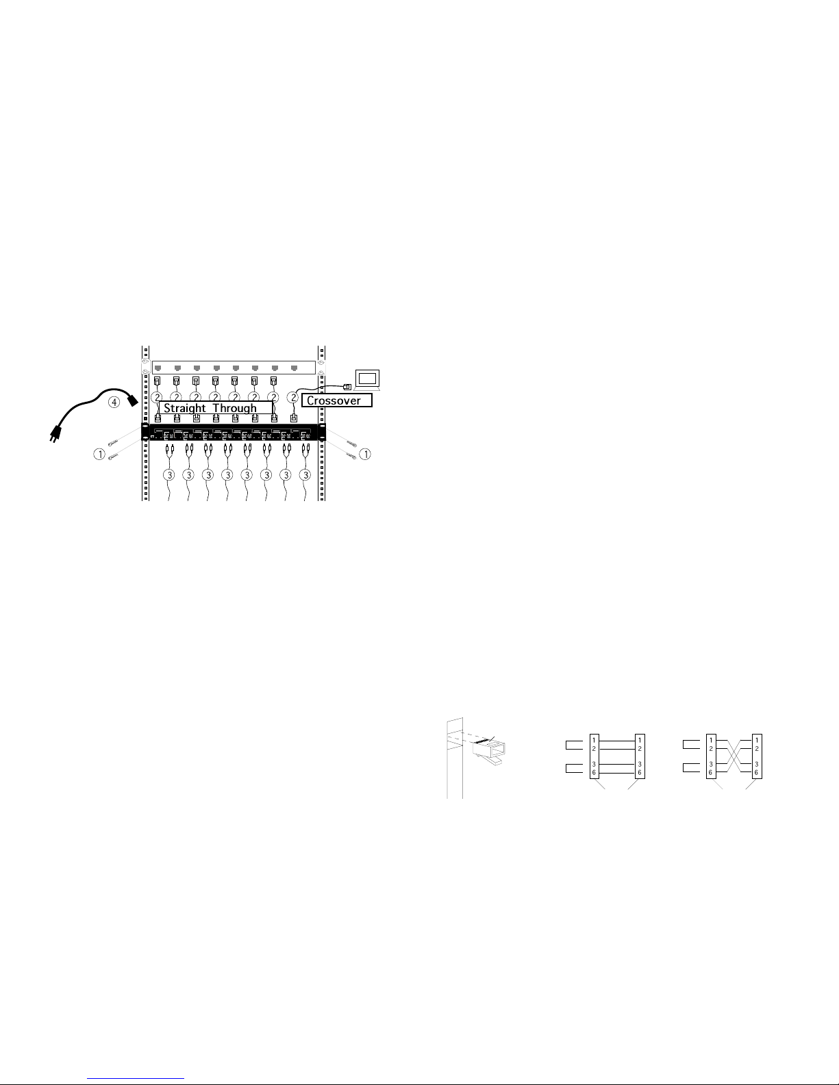
In the example network installation below, the 8-Port Media Converter
provides cable connection and media conversion between a 10BASE-T
switch and remote fiber installations. Other 10BASE-T/10BASE-FL
installations are supported.
To install the 8-Port Media Converter:
1. Mount the 8-Port Media Converter in a 19-inch rack.
• Locate four (4) screws and clip-nuts if necessary (NOT included with
shipment).
• Carefully align 8-Port Media Converter with 19-inch rack rails.
• Install two (2) screws through each bracket into mounting rails.
2. Connect 10BASE-T cables.
• Locate 10BASE-T cables that comply with Ethernet™ 802.3 specifications
and that have male RJ-45 connectors installed at both ends.
• Referring to drawing above and to Configuring 10BASE-T Straight
Through/Crossover Cable Assembly on next page, be certain that the
10BASE-T cable is configured as straight through or crossover as required
for site installation. NOTE: An RJ-45 telephone cable is reverse-wired,
which is NOT the same as a crossover pinout.
3. Connect 10BASE-FL cables.
• Locate 10BASE-FL cables that comply with Ethernet™ 802.3 specifications
and that have two (2) male TX and RX connectors installed at both ends.
• Verify that the fiber products to be connected are 10BASE-FL or FOIRL
compliant. NOTE: Fiber ports on TRANSITION Networks fiber media
converters conform to 10BASE-FL or FOIRL but NOT to 10BaseFB or FDDI.
• Connect media converter TX connector to remote installation RX connector
and media converter RX connector to remote installation TX connector.
4. Connect to external AC power.
• Locate power cord included with shipment.
• Connect the power supply cable to the media converter BEFORE
connecting the power supply cable to the AC outlet.
1. Is the power LED on the media converter illuminated?
NO
• Is the power cord installed properly in the media converter
and in the outlet?
• Contact Technical Support: (800) 260-1312/(800) LAN-WANS.
YES
• Proceed to step 2.
2. Are the RJ Link and FL Link LEDs illuminated?
NO
RJ Link
• Check RJ connectors and UTP cables for proper connection
and pin assignment. (See below.)
NOTE: In the installation
drawing, connections between the switch and the Media Converters
are configured as straight through; the connection between the Media
Converter and the terminal is configured as crossover.
• Refer to Tech Tips available at:
http://www.transition.com
• Contact Technical Support: (800) 260-1312/(800) LAN-WANS.
FL Link
• Verify that fiber cable is multimode (NOT single-mode).
• Check fiber cables for proper connection.
• Verify that TX and RX media converter cables are connected to
RX and TX ports, respectively, on remote 10BASE-FL device.
• Refer to Tech Tips available at:
http://www.transition.com
• Contact Technical Support: (800) 260-1312/(800) LAN-WANS.
YES
• Contact Technical Support: (800) 260-1312/(800) LAN-WANS.
TROUBLESHOOTING SUGGESTIONS
If a Media Converter fails, ask the following questions:
INSTALLATION NOTES
Cable connections between a hub and the media converter must be configured as
straight through. Cable connections between the media converter and a terminal,
transceiver or NIC must be configured as crossover.
The two active pairs in a 10BASE-T network are pins 1 & 2 and pins 3 & 6. Use only
dedicated wire pairs (such as blue/white & white/blue, orange/white & white/orange)
for the active pins.
Configuring 10BASE-T Straight Through/Crossover Cable Assembly
Twisted
Pair #1
Twisted
Pair #2
Crossover Cable
Connectors for like devices
Twisted
Pair #1
Twisted
Pair #2
Straight Through Cable
Connectors for unlike devices
Switch
RX TX
Converter 1
RX TX RX TX RX TX RX TX RX TX RX TX RX TX
Converter 2 Converter 3 Converter 4 Converter 5 Converter 6 Converter 7 Converter 8
Crossview of the
UTP Cable Connector
Top
1
8
view of the RJ-45 Port
 Loading...