

Page 1
The TRANSITION Networks FX-MC01 transceivers connect Fast Ethernet™ hubs and
terminal devices, through a Media Independent Interface (MII) connector, to 1300mn
multimode fiber-optic cable (E-FX-MC01 and E-FX-MC01(SC)) OR to 1300mn singlemode
fiber-optic cable (E-FX-MC01(SM)).
All E-FX-MC01 transceivers can be configured, using a switch on the front of the
transceiver, to operate in full-duplex or in half-duplex mode. A set of switches also on the
front can be used to set a unique physical address for each transceiver.
Fast Ethernet™ Fiber Transceiver
E-FX-MC01, E-FX-MC01(SM), E-FX-MC01(SC)
USER’S GUIDE
TRANSCEIVER TECHNICAL SPECIFICATIONS
Standards IEEE 802.3
Case dimensions 2.8" x 1.75" x 0.75" (71mm x 43mm x 18mm)
Maximum in series: Two (2)
Environment Temperature: 0-40°C (32° to 104° F )
Humidity 10-90%, non condensing
Altitude 0-10,000 feet
Warranty Lifetime
Status LEDs provide the following information:
Minneapolis, MN 55344 USA
E-FX-MC01
Provides an MII connector and a set of
RX (receive) and TX (transmit) ST
100BASE-FX connectors to 1300mn
multimode fiber cable.
E-FX-MC01(SC)
Provides an MII connector and an RX
(receive) and TX (transmit) SC 100BASEFX connector to 1300mn multimode fiber
cable.
E-FX-MC01(SM)
Provides an MII connector and an RX
(receive) and TX (transmit) SC 100BASEFX connector to 1300mn singlemode
fiber cable.
Full/Half: Illuminated green LED indicates full-duplex operation.
RX Flashing or illuminated green LED
indicates packet(s) are being received.
TX Flashing or illuminated green LED
indicates packet(s) are being transmitted.
Link Illuminated green LED indicates the unit
is receiving link pulses from a compliant
device.
Power: Illuminated green LED indicates
100BASE-FX
TRANSCEIVER
E-FX-MC01
TX
Link
Power
123
45
Address (1-5)
HDX
FDX
RX
Full/Half
TX
Link
Power
RX
Full/Half
Compliance Information
UL Listed
C-UL Listed (Canada)
CISPR/EN55022 Class A
FCC Regulations
This equipment has been tested and found to comply with the limits for a class A digital device, pursuant
to part 15 of the FCC rules. These limits are designed to provide reasonable protection against harmful
interference when the equipment is operated in a commercial environment. This equipment generates,
uses, and can radiate radio frequency energy and, if not installed and used in accordance with the
instruction manual, may cause harmful interference to radio communications. Operation of this
equipment in a residential area is likely to cause harmful interference, in which case the user will be
required to correct the interference at the user’s own expense.
Canadian Regulations
This digital apparatus does not exceed the Class A limits for radio noise for digital apparatus set out on
the radio interference regulations of the Canadian Department of Communications.
European Regulations
Warning
This is a Class A product. In a domestic environment this product may cause radio interference in which
case the user may be required to take adequate measures.
Copyright Restrictions
© 1998 TRANSITION Networks.
All rights reserved. No part of this work may be reproduced or used in any form or by any means –
graphic, electronic, or mechanical – without written permission from TRANSITION Networks.
Trademark Notice
All registered trademarks and trademarks are the property of their respective owners. 33036.D
E-FX-MC01
Multimode Fiber
100BASE-FX
TRANSCEIVER
E-FX-MC01
TX
Link
Power
123
45
Address (1-5)
HDX
FDX
RX
Full/Half
E-FX-MC01(SM)
Singlemode Fiber
100BASE-FX
TRANSCEIVER
E-FX-MC01(SM)
TX
Link
Power
123
45
Address (1-5)
HDX
FDX
RX
Full/Half
E-FX-MC01(SC)
Multimode Fiber
100BASE-FX
TRANSCEIVER
E-FX-MC01(SC)
TX
Link
Power
123
45
Address (1-5)
HDX
FDX
RX
Full/Half
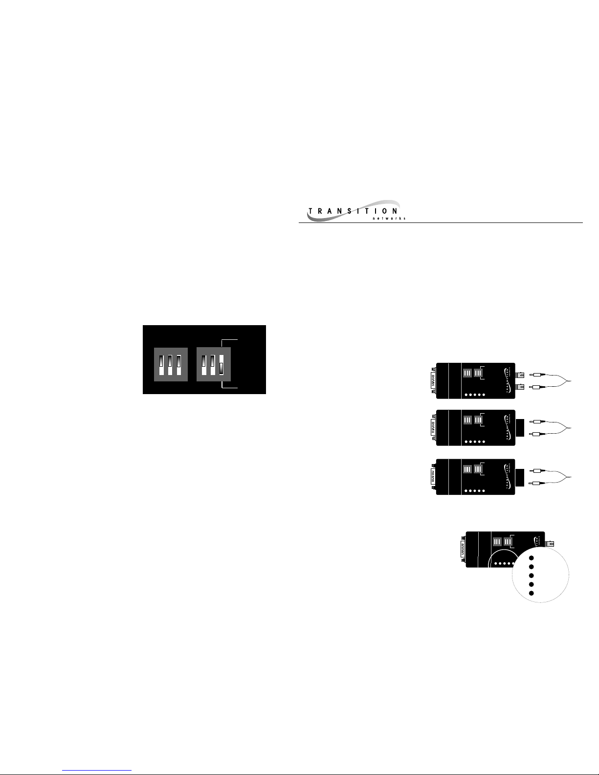
Setting the Transceiver Physical Address
Additive switch settings allow a physical address to be set by selecting (or not
selecting) among the following:
Switch 1 DOWN 2
0
1
Switch 2 DOWN 2
1
2
Switch 3 DOWN 2
2
4
Switch 4 DOWN 2
3
8
Switch 5 DOWN 2
4
16
In the switch setting shown above,
the transceiver physical address is set to 0 (0+0+0+0+0). The data transfer mode
is set to full-duplex.
123
45
Address (1-5)
HDX
FDX
OFF
OFF
Page 2
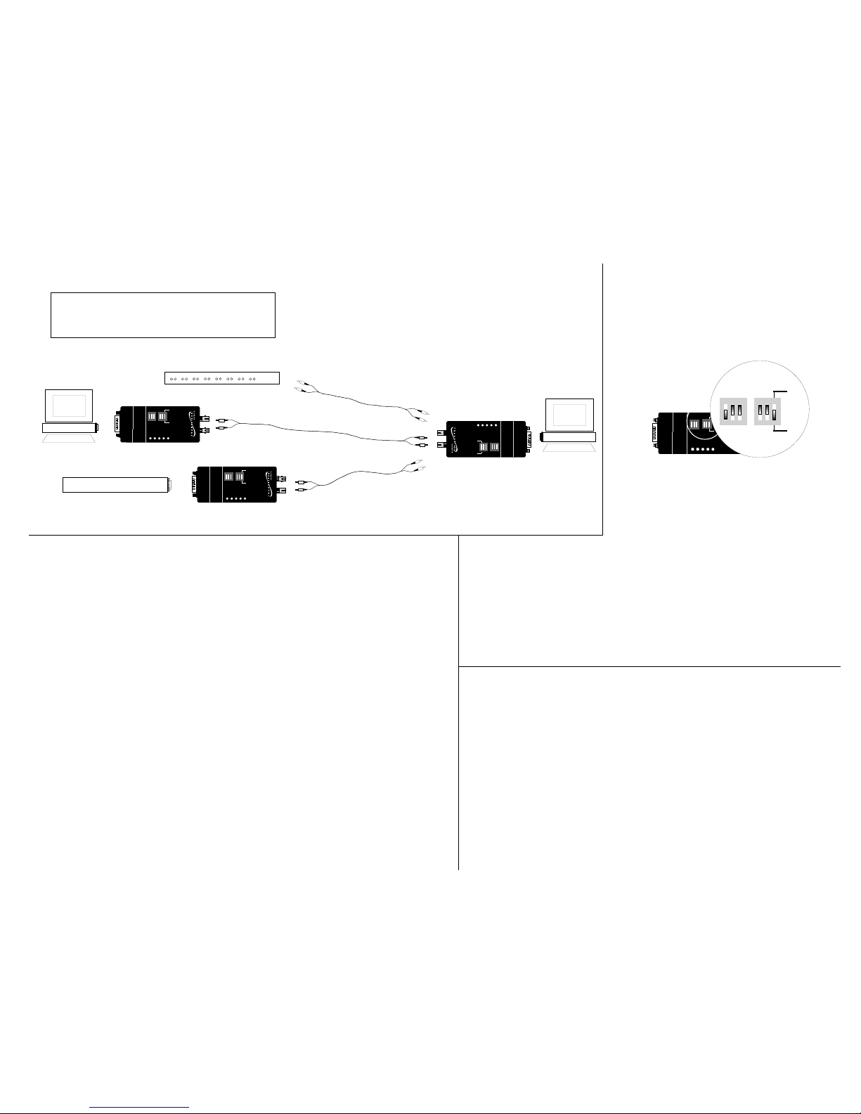
100BASE-FX Hub
OR
OR
RX
100BASE-FX
TRANSCEIVER
E-FX-MC01
Full/Half
TX
Link
Power
123
45
Address (1-5)
HDX
FDX
RX
100BASE-FX
TRANSCEIVER
E-FX-MC01
Full/Half
TX
Link
Power
123
45
Address (1-5)
HDX
FDX
RX
100BASE-FX
TRANSCEIVER
E-FX-MC01
Full/Half
TX
Link
Power
123
45
Address (1-5)
HDX
FDX
Hub with MII connector
1. Is the power LED on the transceiver illuminated?
NO
• Verify that the transceiver is installed properly in the MII port and that the device is
powered ON?
• Contact Technical Support at (800) 260-1312 or at (800) LAN-WANS.
YES
• Proceed to step 2.
2. Is the Link LED illuminated?
NO
• Check the fiber cables for proper connection. (If possible, try a different pair of fiber
cables.)
• Try setting a non-zero physical address.
• Contact Technical Support at (800) 260-1312 or at (800) LAN-WANS.
YES
• Proceed to step 3.
3. Is the fiber cable connected properly?
NO
• Verify that TX and RX cables on transceiver are connected to RX and TX ports,
respectively, on each device.
• Contact Technical Support at (800) 260-1312 or at (800) LAN-WANS.
YES
• Contact Technical Support at (800) 260-1312 or at (800) LAN-WANS.
Troubleshooting the Transceiver
If the E-FX-MC01 transceiver fails, determine the answers to the following questions:
Installation Notes
The physical characteristics of the media cable
must meet or exceed IEEE 802.3 100BASE-FX
specifications.
100BASE-FX CABLE SPECIFICATIONS
1300nm MULTIMODE
Fiber Optic Cable Recommended: 62.5 / 125 µm multimode fiber
Fiber Optic Transmitter Power: Average: -19 dBm
Fiber Optic Receiver Sensitivity: Average: -32.5 dBm
Bit error rate: ≤10
-9
Maximum Cable Distance: 5 kilometers (16,500 feet)
1300nm SINGLEMODE
Fiber Optic Cable Recommended: 9/125 micron single mode fiber
Fiber Optic Transmitter Power: Average: -14 dBm
Fiber Optic Receiver Sensitivity: Average: -33 dBm
Bit error rate: ≤10
-10
Maximum Cable Distance: 20 kilometers (66,000 feet)
Maximum cable distances apply ONLY
to full duplex installations.
Switches 1-5: The transceiver is shipped with
rocker switch 1 set to the default OFF=DOWN
and rocker switches 2-5 set to the default
ON=UP, which sets
the transceiver
physical address to a
value of “1”.
In all known cases, the default rocker switch 15 setting is the correct physical address for
network installations. ONLY IF THIS ADDRESS
SHOULD FAIL, refer to the chart on the back
page for direction for setting the binary
transceiver physical address to a site-specific
value from 1 to 31.
100BASE-FX
TRANSCEIVER
E-FX-MC01
TX
Link
Power
123
45
Address (1-5)
HDX
FDX
RX
Full/Half
FDX
123
45
Address (1-5)
HDX
Switch 6 The transceiver is shipped with rocker switch 6 set to the
default OFF=DOWN, which sets the data-transfer mode to “full-duplex”.
Set the data transfer mode rocker switch to half-duplex (HDX) when the
transceiver is connected to a device that IS NOT capable of full-duplex.
Keep the data transfer mode switch at full-duplex (FDX) when the
transceiver is connected to a device that IS capable of full-duplex.
 Loading...