

Page 1
COMPLIANCE INFORMATION
UL Listed
C-UL Listed (Canada)
CISPR/EN55022 Class A
FCC Regulations
This equipment has been tested and found to comply with the limits for a class A digital device, pursuant
to part 15 of the FCC rules. These limits are designed to provide reasonable protection against harmful
interference when the equipment is operated in a commercial environment. This equipment generates,
uses, and can radiate radio frequency energy and, if not installed and used in accordance with the
instruction manual, may cause harmful interference to radio communications. Operation of this
equipment in a residential area is likely to cause harmful interference, in which case the user will be
required to correct the interference at the user’s own expense.
Canadian Regulations
This digital apparatus does not exceed the Class A limits for radio noise for digital apparatus set out on
the radio interference regulations of the Canadian Department of Communications.
Le présent appareil numérique n'émet pas de bruits radioélectriques dépassant les limites applicables
aux appareils numériques de la class A prescrites dans le Règlement sur le brouillage radioélectrique
édicté par le ministère des Communications du Canada.
European Regulations
Warning
This is a Class A product. In a domestic environment this product may cause radio interference in which
case the user may be required to take adequate measures.
Achtung !
Dieses ist ein Gerät der Funkstörgrenzwertklasse A. In Wohnbereichen können bei Betrieb dieses Gerätes
Rundfunkstörungen auftreten, in weichen Fällen der Benutzer für entsprechende Gegenmaßnahmen
werantwortlich ist.
Attention !
Ceci est un produit de Classe A. Dans un environment domestique, ce produit risque de créer des
interférences radioélectriques, il appartiendra alors à l’utilsateur de prende les measures spécifiques
appropriées
Trademark Notice
All registered trademarks and trademarks are the property of their respective owners.
Copyright Restrictions
© 1999 TRANSITION Networks.
All rights reserved. No part of this work may be reproduced or used in any form or by any means –
graphic, electronic, or mechanical – without written permission from TRANSITION Networks.
Printed in the U.S.A. 33030.E
Der Anschluss dieses Gerätes an ein öffentlickes Telekommunikationsnetz in den EG-Mitgliedstaaten
verstösst gegen die jeweligen einzelstaatlichen Gesetze zur Anwendung der Richtlinie 91/263/EWG zur
Angleichung der Rechtsvorschriften der Mitgliedstaaten über Telekommunikationsendeinrichtungen
einschliesslich der gegenseitigen Anerkennung ihrer Konformität.
The TRANSITION Networks E-FRL-MC04 transceiver is a media access
unit (MAU) that connects the AUI port of any DTE, repeater, or other
network device, either directly or through an AUI cable, to an Ethernet
™
10BASE-FL device through either unshielded or shielded twisted-pair
copper cable and an RJ-45 connector.
Minneapolis, MN 55344 USA
AUI/10BASE-FL
T ransceiver
E-FRL-MC04, E-FRL-MC04(SC),
E-FRL-MC04(SM), E-FRL-MC04(L)
USER’S GUIDE
E-FRL-MC04 in the Network . . . . . . .2
Installation . . . . . . . . . . . . . . . . . . . .3
Operation . . . . . . . . . . . . . . . . . . . . .4
Fault Isolation and Correction . . . . .5
Cable Specifications . . . . . . . . . . . . .6
Technical Specifications . . . . . . . . . .7
Compliance Information . . . . . . . . . .8
CAUTION: RJ connectors are NOT INTENDED FOR CONNECTION TO THE
PUBLIC TELEPHONE NETWORK. Failure to observe this caution could result in
damage to the public telephone network.
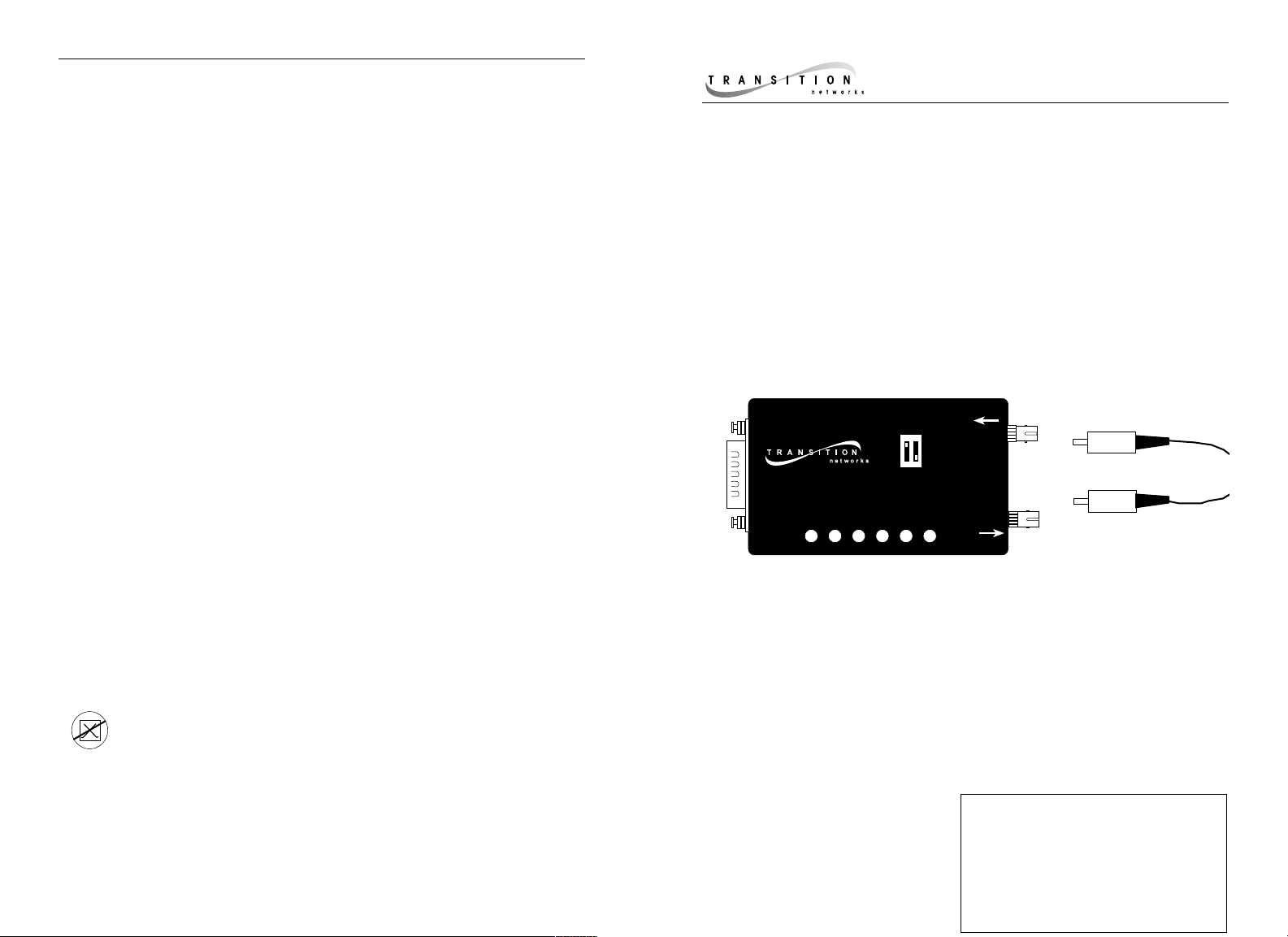
E-FRL-MC04
Provides an AUI connector and a set of
RX (receive) and TX (transmit) ST
10BASE-FL connectors to 850mn
multimode fiber cable.
E-FRL-MC04(SC)
Provides an AUI connector and a set of
RX (receive) and TX (transmit) SC
10BASE-FL connectors to 850mn
multimode fiber cable.
E-FRL-MC04(SM)
Provides an AUI connector and a set of
RX (receive) and TX (transmit) ST
10BASE-FL connectors to 1300mn
singlemode fiber cable.
E-FRL-MC04(L)
Provides an AUI connector and a set of
RX (receive) and TX (transmit) ST
10BASE-FL connectors to 1300mn
multimode fiber cable.
Ethernet
“
10BASE-FL Transceiver
Collisiion
Jabber
Transmit
SQE On
SQE Off
Link
Receive
FDX
HDX
Power
RX
TX
Page 2
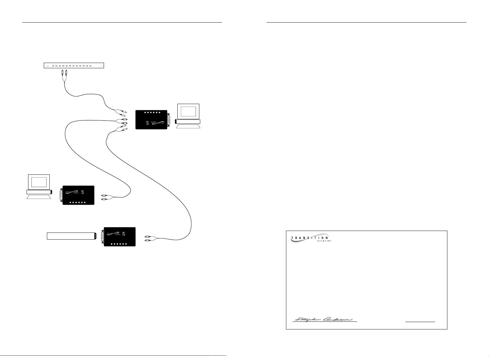
E-FRL-MC04 IN THE NETWORK
NOTE: AUI cable can be used to connect to the transceiver.
TECHNICAL SPECIFICATIONS
Standards IEEE 802.3
Case Dimensions 2.8" x 1.75" x 0.75" (71mm x 43mm x 18mm)
Environment Temperature: 0-40°C (32° to 104° F )
Humidity 10-90%, non condensing
Altitude 0-10,000 feet
Warranty Lifetime
DECLARATION OF CONFORMITY
Name of Mfg: Transition Networks
6475 City West Parkway, Minneapolis MN 55344 USA
Model: AUI/10BASE-FL Transceiver
Part Number: E-FRL-MC04, E-FRL-MC04(SC),E-FRL-MC04(SM),
E-FRL-MC04(L)
Regulation: EMC Directive 89/336/EEC
Purpose: To declare that the E-FRL-MC04 to which this declaration refers is in
conformity with the following standards.
EMC-CISPR 22: 1985 Class A; EN 55022: 1988 Class A; EN 50082-1:1992;
EN 60950 A4:1997; IEC 801.2, IEC 801.3, and IEC 801.4; IEC 950
I, the undersigned, hereby declare that the equipment specified above conforms to the
above Directive(s) and Standard(s).
_August 11, 1999_____
Stephen Anderson, Vice-President of Engineering Date
10BASE-Fl Hub
OR
SQE = ON
OR
SQE = ON
Hub with MII connector
SQE = OFF
Page 3

CABLE SPECIFICATIONS
The physical characteristics of the media cable must meet or exceed IEEE 802.3
specifications.
Fiber-Optic Interface
850nm MULTIMODE
Fiber Optic Cable Recommended: 62.5 / 125 µm multimode fiber
Fiber Optic Transmitter Power: Average: -15 dBm
Fiber Optic Receiver Sensitivity: Average : -33 dBm
Bit error rate: ≤10
-10
Maximum Cable Distance: 2 kilometers (6,600 feet)
1300nm MULTIMODE
Fiber Optic Cable Recommended: 62.5 / 125 µm multimode fiber
Fiber Optic Transmitter Power: Average: -17 dBm
Fiber Optic Receiver Sensitivity: Average: -35 dBm
Bit error rate: ≤10
-9
Maximum Cable Distance: 5 kilometers (16,500 feet)
1300nm SINGLEMODE
Fiber Optic Cable Recommended: 9/125 micron single mode fiber
Fiber Optic Transmitter Power: Average: -16 dBm
Fiber Optic Receiver Sensitivity: Average: -33 dBm
Bit error rate: ≤10
-10
Maximum Cable Distance: 20 kilometers (66,000 feet)
AUI (DB-15) Interface
Parameter Minimum Typical Maximum
Transmit
Transmit threshold voltage level: -140mV -170mV -190mV
Transmit turn on delay: 100ns
Transmit steady propagation delay: 15ns 50ns
Transmit loop back start up delay: 500ns
Transmit turn off to data idle: 400ns 2100ns
SQE test delay: 0.6 µ sec 1.6 µ sec
SQE test duration: 0.5 µ sec 1.0 µ sec 1.5 µ sec
Receive
Receive turn on delay: 350ns
Receive steady propagation delay: 15ns 50ns
Differential output voltage (RX(-/+)): (+/-)550mV (+/-)1200
Differential output voltage (col(-/+)): (+/-)550mV (+-)1200
Differential output rise time (RX(-/+), col(-/+)): 4ns
Differential output fall time (RX(-/+), col(-/+)): 4ns
Collision
Time for SQE to deact. after collision: 450ns 700ns
Collision frequency: 8.5MHz 11.5MHz
Collision pulse duty cycle: 40% 50% 60%
SQE test delay: 0.6 µ sec 1.6 µ sec
Jabber activation delay: 20ms 70ms 150ms
INSTALLATION
Set Switches
Two (2) switches are located on the top of the transceiver.
SQE Off/SQE On: Selects SQE test function. Set
to SQE On when connecting to IEEE 802.3
compliant repeaters. Set to SQE Off when
connecting to other devices.
HDX/FDX: Selects either half-duplex (HDX) or full-duplex (FDX) data
transmission. Set according to network installation.
Install Cable
NOTE: See page 6 for cable specifications.
1. Locate or build 10BASE-FL compliant cables with male twostranded TX to RX connectors at both ends.
2. Connect male TX and RX cable connectors at one end of cable to
TX and RX female connectors, respectively, on transceiver.
3. Connect male TX and RX cable connectors at other end of cable
to RX and TX connectors of 802.3 compliant fiber device..
Connect to Power
The E-FRL-MC04 is powered through the AUI connection.
SQE Off
HDX
SQE On
FDX
Page 4

OPERATION
After installation, the transceiver should function without operator intervention.
Status LEDs
Use the status LEDs to monitor transceiver operation in the network.
Jabber : Illuminated red LED indicates that unit is disabled.
Collision: Flashing or illuminated red LED
indicates collisions.
Transmit: Flashing or illuminated green LED
indicates packet(s) are being
transmitted.
Receive: Flashing or illuminated green LED
indicates packet(s) are being received.
Link Illuminated green LED indicates the
unit is receiving link pulses from a
compliant device.
Power: Illuminated green LED indicates
connection to external power.
FAULT ISOLATION and CORRECTION
If the transceiver fails, determine the answers to the following questions:
1. Is the power LED on the transceiver illuminated?
NO
• Verify that the transceiver is installed properly in the AUI port and
that the device is powered ON.
• Contact Technical Support at (800) 260-1312 or at (800) LAN-
WANS.
YES
• Proceed to step 2.
2. Is the Link LED illuminated?
NO
• Check the fiber cables for proper connection. (If possible, try a
different pair of fiber cables.)
• Contact Technical Support at (800) 260-1312 or at (800) LAN-
WANS.
YES
• Proceed to step 3.
3. Is the fiber cable connected properly?
NO
• Verify that TX and RX cables on transceiver are connected to RX
and TX ports, respectively, on each device.
• Contact Technical Support at (800) 260-1312 or at (800) LAN-
WANS.
YES
• Contact Technical Support at (800) 260-1312 or at (800) LAN-
WANS.
H
Jabber
Collisiion
Transmit
Receive
Link
SQE
Power
 Loading...