

Page 1
Receive
Link
Power
Transmit
Collision
Jabber
SQE
On
Off
Ethernet™
Single Mode FL Transceiver
E-FRL-MC03
Mpls, MN 55344
RX
TX
networks
TRANSITION
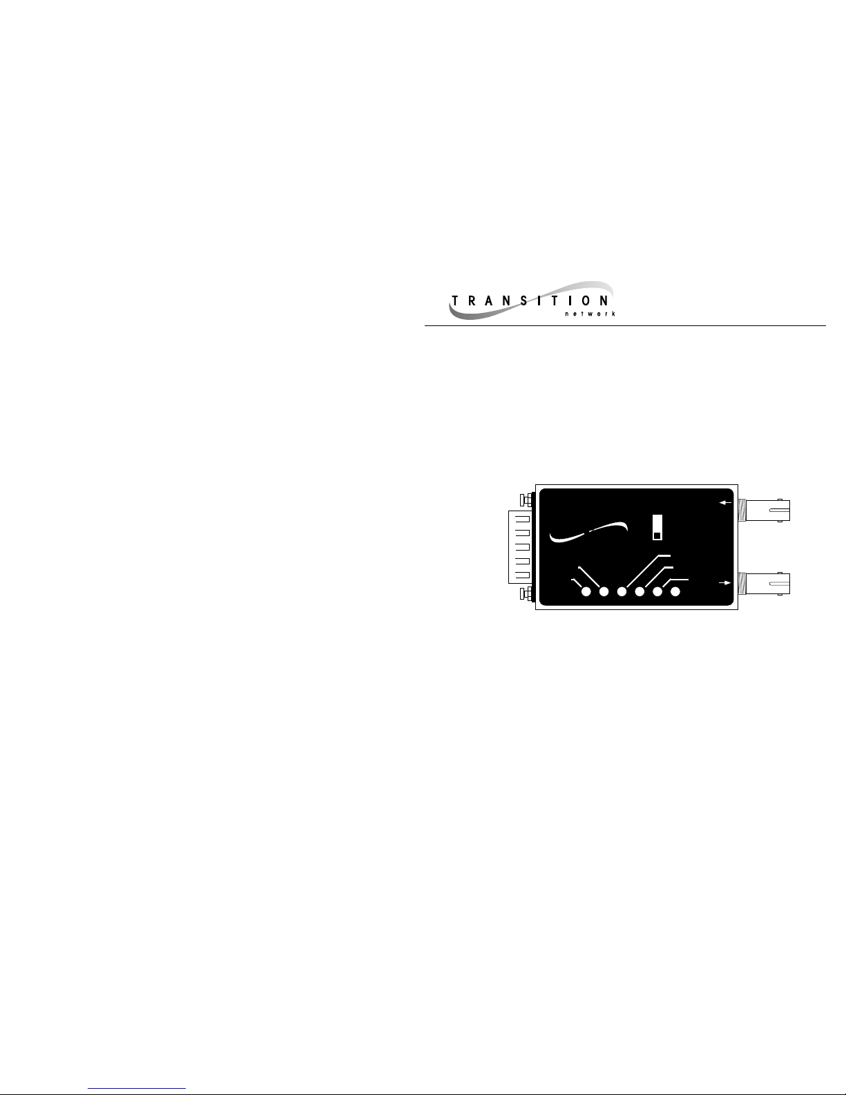
The Transition Networks Single Mode Fiber Optic Transceiver is used to connect
Ethernet IEEE 802.3 AUI (DB-15) nodes to a fiber optic medium using standard ST type
connectors (SMA available).
The compact size of the transceiver allows a direct connection to most AUI ports on
Ethernet compatible workstations, cards, and multiport repeaters.
LEDs indicate status of all MAU functions: Jabber, Collision, Transmit, Receive, Link,
and Power. An external dip switch turns the SQE heartbeat On and Off. The 1300 nm
Single Mode Fiber Optic Transceiver is fully IEEE 802.3 compliant, allowing network
managers to utilize multiple components from multiple vendors without compatibility
problems.
Single Mode Fiber Optic Transceiver
E-FRL-MC03
USER’S GUIDE
FCC Regulations:
Note: This equipment has been tested and found to comply with the limits for a Class A digital device, pursuant
to Part 15 of the FCC Rules. These limits are designed to provide reasonable protection against harmful
interference when the equipment is operated in a commercial environment. This equipment generates, uses, and
can radiate radio frequency energy and, if not used in accordance with the instruction manual, may cause
harmful interference to radio communications. Operation of this equipment in a residential area is likely to
cause harmful interference in which case the user will be required to correct the interference at his own cost.
Canadian Regulations:
Note: This digital apparatus does not exceed the Class A limits for radio noise for digital apparatus set out on the
radio interference regulations of the Canadian Department of Communications.
Copyright Restrictions
© 1995, 1997 Transition Networks, Inc.
All rights reserved. No part of this work may be reproduced or used in any form or by any means - graphic,
electronic, or mechanical - without written permission from Transition Networks, Inc.
Trademarks:
Ethernet is a registered trademark of the Xerox Corporation, Inc.
TRANSITION Networks is a trademark of TRANSITION Networks, Inc. 7358.I
Specifications:
Case size dimensions: 3.7" x1.75" x 0.8" (94 mm x 44 mm x 20 mm)
Standard: Ethernet IEEE 802.3, 1300 nm
Fiber Optic Interface
Fiber Connection: ST type connectors (SMA type available upon request)
Fiber Optic Cable Maximum Distance: 5,000 meters- 20,000 meters
Fiber Optic Cable Recommended: 9/125 micron single mode fiber
Fiber Optic Transmitter Power: Typical transmit power: -22.5dBm
Best case transmit power: -18.5dBm
Worst case transmit power:-28.5dBm
Fiber Optic Receiver Sensitivity: Best case fiber sensitivity: -35dBm
Worst case fiber sensitivity:-30dBm
Bit error rate: ≤10
-9
Environment: 0–50 degrees C, 10–90% humidity, non-condensing,
0–10,000 foot altitude
WARRANTY: FIVE YEARS
Minneapolis, MN 55344 USA
Status LEDs provide the following information:
Transmit: Flashing or illuminated green LED indicates packet(s) are being transmitted.
Receive: Flashing or illuminated green LED indicates packet(s) are being received.
Link Illuminated green LED indicates the unit is receiving link pulses from a
compliant device.
Power: Illuminated green LED indicates normal operation.
Collision: Flashing or illuminated red LED indicates collisions are occurring.
Jabber: Illuminated red LED indicates the unit is disabled.
AUI (DB-15) Interface
Parameter Minimum Typical Maximum
Transmit
Transmit threshold voltage level: -140mV -170mV -190mV
Transmit turn on delay: 100ns
Transmit steady propagation delay: 15ns 50ns
Transmit loop back start up delay: 500ns
Transmit turn off to data idle: 400ns 2100ns
SQE test delay: 0.6 µ sec 1.6 µsec
SQE test duration: 0.5 µ sec 1.0 µ sec 1.5 µ sec
Receive
Receive turn on delay: 350ns
Receive steady propagation delay: 15ns 50ns
Differential output voltage (RX(-/+)): (+/-)550mV (+/-)1200
Differential output voltage (col(-/+)): (+/-)550mV (+-)1200
Differential output rise time (RX(-/+), col(-/+)): 4ns
Differential output fall time (RX(-/+), col(-/+)): 4ns
Collision
Time for SQE to deact. after collision: 450ns 700ns
Collision frequency: 8.5MHz 11.5MHz
Collision pulse duty cycle: 40% 50% 60%
SQE test delay: 0.6 µ sec 1.6 µsec
Jabber activation delay: 20ms 70ms 150ms
Page 2
SQE Switch in
ON Position
Receive
Link
Power
Transmit
Collision
Jabber
SQE
On
Off
Ethernet™
Single Mode FL Transceiver
E-FRL-MC03
Mpls, MN 55344
RX
TX
networks
TRANSITION
Receive
Link
Power
Transmit
Collision
Jabber
SQE
On
Off
Ethernet™
Single Mode FL Transceiver
E-FRL-MC03
Mpls, MN 55344
RX
TX
networks
TRANSITION
SQE Switch in
OFF Position
110-120
220-240
2A, 250V
Input Power: 100-240 V
50/60 Hz
0.5 A
AUX
SERIAL
AUI
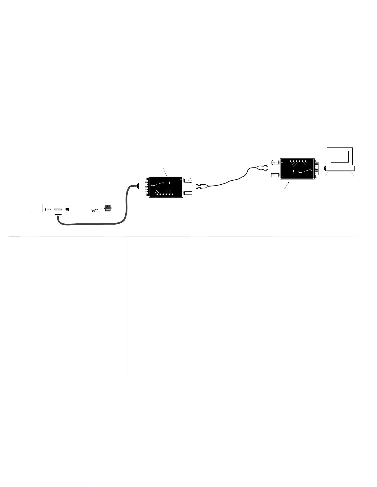
Transceiver Connection with SQE Switch Setting
1. Is the power LED on the transceiver illuminated?
NO
• Verify that the transceiver is installed properly in the AUI port and that the device is
powered ON?
• Contact Technical Support at (800) 260-1312 or at (800) LAN-WANS.
YES
• Proceed to step 2.
2. Is the Link LED illuminated?
NO
• Check the single mode fiber cables for proper connection. (If possible, try a different
pair of fiber cables.)
• Contact Technical Support at (800) 260-1312 or at (800) LAN-WANS.
YES
• Proceed to step 3.
3. Is the fiber cable connected properly?
NO
• Check fiber cables for proper connection.
• Verify that TX and RX cables on transceiver are connected to RX and TX ports,
respectively, on each device.
• Contact Technical Support at (800) 260-1312 or at (800) LAN-WANS.
YES
• Be certain that the SQE switch is set to ON or
OFF, according to the AUI connection.
• Verify that the fiber products to be connected
are IEEE 802.3 compliant. (The TRANSITION
Networks E-FRE-MC03 transceiver is a 1300
nm single mode transceiver. This transceiver
should be used in pairs to connect two DTE
AUI devices via single mode fiber optic cable.)
• 9/125 micron single mode cable is
recommended.
• The maximum dBm loss for the fiber cable
should not exceed 8.2 dBm.
• The “Link” LED on both transceivers will be
illuminated when the cable is connected
properly and the units are powered.
Troubleshooting the Transceiver
Installation Notes
If the E-FRL-MC03 transceiver fails, determine the answers to the following questions:
SQE Heartbeat: Enable - The SQE switch should
be enabled (ON) when the
transceiver is connected to a
DTE or workstation.
Disable - The SQE switch
should be disabled (OFF) when
the transceiver is connected to
the AUI port of an Ethernet
repeater hub.
 Loading...