

Page 1
Both media converters function at 4Mb/s or 16Mb/s in half-duplex mode or,
when connected to devices capable of full-duplex connectivity, in full-duplex
mode for up to 32Mb/s total throughput.
NOTE: The fiber interface LEDs are NOT illuminated until the twisted-pair side
has been initialized and asserts a phantom voltage to the fiber. (See a description
of the activity of the Token Ring twisted-pair to fiber signal in “Media Converters
in the Network” on page 4.)
MEDIA CONVERTER TECHNICAL SPECIFICATIONS
Standards IEEE 802.5, 802.5j
Delay 50nsec round trip
Environment Temperature: 0-40°C (32° to 104° F )
Humidity 10-90%, non condensing
Altitude 0-10,000 feet
Warranty Five years
CAUTION: RJ connectors are NOT INTENDED FOR CONNECTION TO THE
PUBLIC TELEPHONE NETWORK. Failure to observe this caution could result in
damage to the public telephone network.
Compliance Information
UL Listed
C-UL Listed (Canada)
CISPR/EN55022 Class A
FCC Regulations
This equipment has been tested and found to comply with the limits for a class A digital device, pursuant
to part 15 of the FCC rules. These limits are designed to provide reasonable protection against harmful
interference when the equipment is operated in a commercial environment. This equipment generates,
uses, and can radiate radio frequency energy and, if not installed and used in accordance with the
instruction manual, may cause harmful interference to radio communications. Operation of this
equipment in a residential area is likely to cause harmful interference, in which case the user will be
required to correct the interference at the user’s own expense.
Canadian Regulations
This digital apparatus does not exceed the Class A limits for radio noise for digital apparatus set out on
the radio interference regulations of the Canadian Department of Communications.
European Regulations
Warning
This is a Class A product. In a domestic environment this product may cause radio interference in which
case the user may be required to take adequate measures.
Copyright Restrictions
© 1998, 1999 TRANSITION Networks.
All rights reserved. No part of this work may be reproduced or used in any form or by any means –
graphic, electronic, or mechanical – without written permission from TRANSITION Networks.
Trademark Notice
All registered trademarks and trademarks are the property of their respective owners. 33087.D
Der Anschluss dieses Gerätes an ein öffentlickes Telekommunikationsnetz in den EG-Mitgliedstaaten
verstösst gegen die jeweligen einzelstaatlichen Gesetze zur Anwendung der Richtlinie 91/263/EWG zur
Angleichung der Rechtsvorschriften der Mitgliedstaaten über Telekommunikationsendeinrichtungen
einschliesslich der gegenseitigen Anerkennung ihrer Konformität.
The TRANSITION Networks slide-in-module media converters, C/TR-CF-01 and
C/TR-CF-01(SM), designed to be installed in the TRANSITION Networks Media
Conversion Center, E-MCC-1600, connect unshielded or shielded Token Ring
twisted-pair copper cable to Token Ring multimode fiber-optic cable OR
singlemode fiber-optic cable.
Minneapolis, MN 55344 USA
Token Ring Copper/Fiber
Slide-In-Module Media Converters
C/TR-CF-01, C/TR-CF-01(SM)
USER’S GUIDE
Multimode
Fiber
UTP or STP
Copper
C/TR-CF-01
Fiber Twisted Pair
Token Ring
C/TR-CF-01
UTP or STP
Copper
Singlemode
Fiber
C/TR-CF-01
Fiber Twisted Pair
Token Ring
C/TR-CF-01(SM
)
C/TR-CF-01
Provides a Token Ring RJ-45 twisted-pair
connector and an RX (receive) and a TX
(transmit) ST connector to multimode
fiber-optic cable for fiber network
extension distances up to 2 kilometers.
C/TR-CF-01(SM)
Provides a Token Ring RJ-45 twisted-pair
connector and an RX (receive) and a TX
(transmit) ST connector to singlemode
fiber-optic cable for fiber network
extension distances up to 15 kilometers.
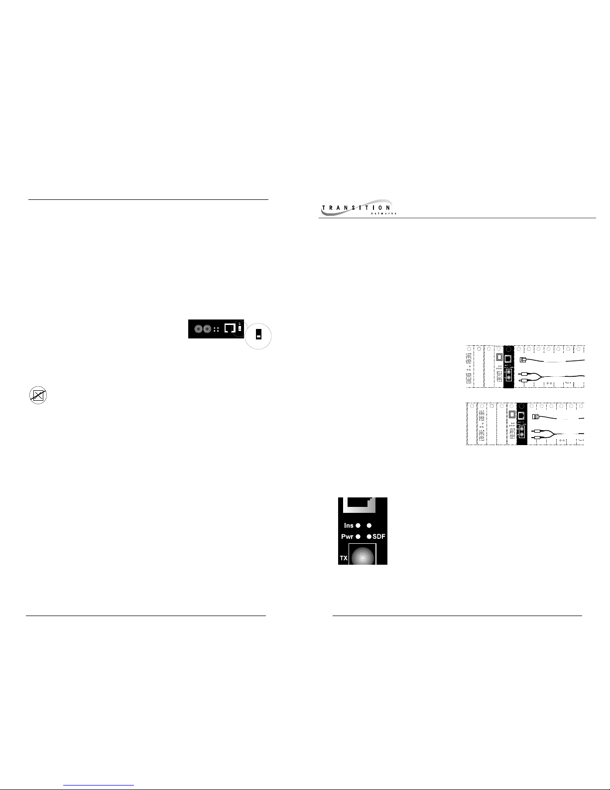
P(o)w(e)r Steady green LED indicates connection to
external AC power.
Ins(erted) Steady green LED indicates twisted-pair and
fiber connections negotiated link.
S(ignal) D(etect) C(opper) Steady green LED indicates
twisted-pair link is up and ready to insert.
S(ignal) D(etect) F(iber) Steady green LED indicates fiber
link is up and ready to insert.
SDC
Twis
t
Status LEDs
The switch on the side of the media converter
provides the following settings:
Norm(al) Used for most network operation.
L(oop-back) S(witch) Used ONLY at the direction of
Transition Networks Technical Support.
NOTE: For more information, go to www.transition.com/support, select
Tech Tips, and then select the Token Ring media converter.
Switch:
10BASE-T
Fiber
RX
TX
Twisted-pair
Fiber
UTP/STP
Pwr
SDC
Ins
SDF
Norm
Norm
LS
Page 2

2
TOKEN RING CABLE SPECIFICATIONS
INSTALLATION
Twisted-pair Cable
• Category 5 twisted-pair cable is recommended; Category 3 and 4 are
supported at reduced cable lengths.
Fiber Extension Cable
• Be certain that the fiber extension cable is correct for distances required at
the site installation.
CAUTION: Wear a grounding device and observe electrostatic
discharge precautions when installing Media Converter Slide-inModule(s) in the 16-Slot Media Conversion Center. Failure to observe
this caution could result in damage to, and subsequent failure of, the
Media Converter Slide-in-Module(s).
Set the switches accordng to the chart on page 3 BEFORE installing
slide-in-module media converter in the media conversion center; if
necessary, refer to the chart on pages 4-5 to determine network
considerations.
Be certain that the media converter 1: mode, 2: active/passive state,
3: IEEE 802.5j compliance/non-compliance, and 4: twisted-pair cable
configuration (straight through/RO or crossover/RI) are set correctly for
the site installation.
The physical characteristics of the media cable must meet or exceed IEEE 802.5
and 802.5j specifications.
7
FIBER CABLE AND CONNECTOR SPECIFICATIONS
Cable Characteristics:
MULTIMODE
Fiber Optic Cable Recommended: 62.5 / 125 µm multimode fiber
Fiber Optic Transmitter Power: min: -19.0
dBm
max: -14.0 dBm
Fiber Optic Receiver Sensitivity: min: -32.5 dBm
max: -14.0 dBm
Wavelength: 850nM
Bit error rate: ≤10
-9
Maximum Cable Distance: 2 kilometers
SINGLEMODE
Fiber Optic Cable Recommended: 9 µm singlemode fiber
Fiber Optic Transmitter Power: min: -25.0
dBm max: -22.0 dBm
Fiber Optic Receiver Sensitivity: min: -32.5 dBm max: -14.0 dBm
Wavelength: 1300nM
Bit error rate: ≤10
-9
Maximum Cable Distance: 15 kilometers
Connector Characteristics: ST type connectors (SMA type available)
TWISTED PAIR CABLE AND CONNECTOR SPECIFICA TIONS
Cable Characteristics:
Category 3 wire or better is required; category 5 wire is recommended. Either
shielded twisted pair (STP) or unshielded twisted pair (UTP) can be used. DO
NOT USE FLAT OR SILVER SATIN WIRE.
Category 3:
Gauge 24 to 22 AWG
Attenuation 28 dB/1000’ @ 10 MHz
Differential Characteristic Impedance 100 Ω ±10% @ 10 MHz
Category 5:
Gauge 24 to 22 AWG
Attenuation 20 dB/1000’ @ 10 MHz
Differential Characteristic Impedance 100 Ω ±10% @ 10 MHz
Maximum Cable Distance: 50 meters (165 feet)
Connector Characteristics:
Twisted pair connection requires two active pairs
configured as straight through. The two active
pairs in a Token Ring network are pins 4 & 5 and
pins 3 & 6. Use only dedicated wire pairs (such
as blue/white & white/blue, orange/white &
white/orange) for the active pins.
3
4
5
6
Twisted
Pair #1
Twisted
Pair #2
Straight Through Cable
3
4
5
6
Setting Configuration Switch
NOTE: Media Converter Slide-in-Modules can be installed in any
installation slot, in any order.
To install the Media Converter Slide-in-Module in the E-MCC-1600
chassis:
1. Remove Media Converter Slide-in-Module protective plate from
selected installation slot by removing two screws that secure plate to
front of E-MCC-1600. Retain one installation screw.
2. Carefully slide Media Converter Slide-in-Module into installation slot,
aligning Media Converter Slide-in-Module with installation guides.
NOTE: Ensure that the Media Converter Slide-in-Module is firmly
seated against the backplane.
3. Secure Slide-in-Module by installing retained installation screw.
Installing Slide-In-Module(s)
Installing Network Cable
C/TR-CF-01
Page 3

3
6
1. Is the p(o)w(e)r LED on the media converter illuminated?
NO
• Is the Slide-In-Module properly connected to the Media Conversion
Center chasis backplane?
• Is the Power Supply Module properly connected both to the Media
Conversion Center chasis backplane and to the AC outlet?
• Are the two sides of the network the same speed: 4Mb/s or
16Mb/s?
• Contact Technical Support: (800) 260-1312/(800) LAN-WANS.
YES
• Proceed to step 2.
2. Is the S(ignal) D(etect) C(opper) LED illuminated?
NO
• Check twisted pair cables for proper connection.
• Check RJ-45 Pinning Switch for correct twisted pair cable
configuration.
• Contact Technical Support: (800) 260-1312/(800) LAN-WANS.
YES
• Proceed to step 3.
3. Is the S(ignal) D(etect) F(iber) LED illuminated?
NO
• Check fiber cables for proper connection.
• Verify that TX and RX cables on media converter are
connected to RX and TX ports, respectively, on other device.
• Contact Technical Support: (800) 260-1312/(800) LAN-WANS.
YES
• Proceed to step 4.
4. Is the Ins(erted) LED illuminated?
NO
• Restart the workstation to restart the initialization process.
• Contact Technical Support: (800) 260-1312/(800) LAN-WANS.
YES
• Contact Technical Support: (800) 260-1312/(800) LAN-WANS.
TROUBLESHOOTING SUGGESTIONS
NOTE: The switches are located directly on the C/TR-CF-01 Slide-InModule circuit board.
Switch settings shown below are used when configuring straightthrough/RO or crossover/RI cable configuration, network installation mode
(1-4), active or passive state of attached concentrator, and network
compliance or non-compliance with the IEEE 802.5j standard.
1234
1234
1234
1234
1234
1234
1234
1234
Mode 1: Selected when installing
media converter between station
and fiber extension.
Mode 2: Selected when installing
media converter between fiber extension
and active concentrator RI or lobe port.
Mode 3: Selected when installing
media converter between fiber extension
and passive concentrator RI port.
Mode 4: Selected when installing
media converter between passive/active
concentrator RO port and fiber extension.
Active: Selected when installing
media converter to active concentrator
Ring port.
Passive: Selected when installing
media converter to passive concentrator
Ring port.
802.5j: Selected when installing
media converter in 802.5j-compliant
network.
Non-802.5j: Selected when installing
media converter in non-802.5j-compliant
network.
C(oncentrator)
/R(ing) O(ut):
Selected when
installing
media converter
to active/passive
concentrator
RO port.
S(tation)
/R(ing) I(n):
Selected when
installing
media converter
to active/passive
concentrator
RI port.
SWITCH SETTINGS
C/TR-CF-01
Page 4

The fiber standard to which the media converters comply is the approved IEEE 802.5j standard. However,
using a switch setting, the media converter can be adapted to some of the proprietary implementations that
evolved before the standard. This proprietary mode reduces the protocol frequency to 1-10kilohertz.
Token Ring topology combines the physical star with the logical ring. Any break in the Token Ring prevents
transmission of the ‘token’ on which the Token Ring protocol is based and therefore prevents data
transmission. Token Ring concentrators implement a loopback function which, in the event of a break in the
ring, loops back the ring to isolate the break. Transition Networks Token Ring media converters are designed
to preserve this fault-recovery feature.
Insertion into the Token Ring is always initiated when the station or concentrator Ring-Out port asserts a
phantom voltage onto the twisted-pair line. The media converter detects this voltage and generates an
‘insertion key' onto the fiber, then loops back the twisted-pair receive to transmit and the fiber receive to
transmit. When an ‘Insertion Key
Echo' is received on the fiber, the
media converter disables the
loopback and passes the twisted-pair
receive to fiber transmit and the fiber
receive to the twisted-pair transmit.
On the other side of the fiber, the
converter drives phantom voltage
and detect for a valid link and the
fiber and twisted-pair interfaces are
in a loopback state. Upon detecting a
valid link, the fiber and twisted-pair
interfaces disable the loopback.
Thus, the Token Ring path is not
opened until a full check from end to
end is done, protecting the integrity
of the Token Ring.
MEDIA CONVERTERS IN THE NETWORK
S/RO C/RI
9V DC Input
TR-CF-01
UTP/STP
Fiber
Token Ring Twisted Pair to
Fiber Media Converter
RJ-45
Pinning
Config
Switches
1 2 3 4
2 kilometers - multimode
15 kilometers - singlemode
Active Concentrator
RI RO
Active Concentrator
RI RO
Active Concentrator RO to Active Concentrator RI
C/RO S/RI 1 2 3 4
C/RO S/RI 1 2 3 4
Set RJ-45 switch to C/RO.
Set Switch 1 & 2 to Mode 4.
Set Switch 3 to Active.
Set Switch 4 according to network
803.5j compliance.
Set RJ-45 switch to S/RI.
Set Switch 1 & 2 to Mode 2.
Set Switch 3 to Active.
Set Switch 4 according to network
803.5j compliance.
Direction of phantom voltage drive (twisted-pair)
or of 'insertion key' generation (fiber)
S/RO C/RI
9V DC Input
TR-CF-01
UTP/STP
Fiber
Token Ring Twisted Pair to
Fiber Media Converter
RJ-45
Pinning
Config
Switches
1 2 3 4
2 kilometers - multimode
15 kilometers - singlemode
Active Concentrator
RI RO
Active Station to Active Concentrator Lobe Port
C/RO S/RI 1 2 3 4
Set RJ-45 switch to S/RI.
Set Switch 1 & 2 to Mode 1.
Set Switch 3 to Active.
Set Switch 4 according to network
803.5j compliance.
C/RO S/RI 1 2 3 4
Set RJ-45 switch to C/RO.
Set Switch 1 & 2 to Mode 2.
Set Switch 3 to Active.
Set Switch 4 according to network
803.5j compliance.
Direction of phantom voltage drive (twisted-pair)
or of 'insertion key' generation (fiber)
S/RO C/RI
9V DC Input
TR-CF-01
UTP/STP
Fiber
Token Ring Twisted Pair to
Fiber Media Converter
RJ-45
Pinning
Config
Switches
1 2 3 4
2 kilometers - multimode
15 kilometers - singlemode
Passive Concentrator
RI RO
Passive Concentrator
RI RO
Set RJ-45 switch to S/RI
Set Switch 1 & 2 to Mode 3.
Set Switch 3 to Passive.
Set Switch 4 according to network
803.5j compliance.
Set RJ-45 switch to C/RO.
Set Switch 1 & 2 to Mode 4.
Set Switch 3 to Passive.
Set Switch 4 according to network
803.5j compliance.
Passive Concentrator RO to Passive Concentrator RI
Direction of phantom voltage drive (twisted-pair)
or of 'insertion key' generation (fiber)
C/RO S/RI 1 2 3 4
C/RO S/RI 1 2 3 4
C/TR-CF-01
 Loading...