

Page 1
COMPLIANCE INFORMATION
UL Listed , C-UL Listed (Canada)
CISPR/EN55022 Class A & B
CE Mark
FCC Regulations
This equipment has been tested and found to comply with the limits for a class A & B digital device,
pursuant to part 15 of the FCC rules. These limits are designed to provide reasonable protection against
harmful interference when the equipment is operated in a commercial environment. This equipment
generates, uses, and can radiate radio frequency energy and, if not installed and used in accordance with
the instruction manual, may cause harmful interference to radio communications. Operation of this
equipment in a residential area is likely to cause harmful interference, in which case the user will be
required to correct the interference at the user’s own expense.
Canadian Regulations
This digital apparatus does not exceed the Class A & B limits for radio noise for digital apparatus set out
on the radio interference regulations of the Canadian Department of Communications.
Le présent appareil numérique n'émet pas de bruits radioélectriques dépassant les limites applicables
aux appareils numériques de la class A & B prescrites dans le Règlement sur le brouillage radioélectrique
édicté par le ministère des Communications du Canada.
European Regulations
Warning
This is a Class A & B product. In a domestic environment this product may cause radio interference in
which case the user may be required to take adequate measures.
Achtung !
Dieses ist ein Gerät der Funkstörgrenzwertklasse A & B. In Wohnbereichen können bei Betrieb dieses
Gerätes Rundfunkstörungen auftreten, in weichen Fällen der Benutzer für entsprechende
Gegenmaßnahmen werantwortlich ist.
Attention !
Ceci est un produit de Classe A & B. Dans un environment domestique, ce produit risque de créer des
interférences radioélectriques, il appartiendra alors à l’utilsateur de prende les measures spécifiques
appropriées
Trademark Notice
All registered trademarks and trademarks are the property of their respective owners.
Copyright Restrictions
© 2000, 2002 TRANSITION Networks.
All rights reserved. No part of this work may be reproduced or used in any form or by any means –
graphic, electronic, or mechanical – without written permission from TRANSITION Networks.
Printed in the U.S.A. 33177.D
CAUTION: RJ connectors are NOT INTENDED FOR CONNECTION TO THE
PUBLIC TELEPHONE NETWORK. Failure to observe this caution could result in
damage to the public telephone network.
Der Anschluss dieses Gerätes an ein öffentlickes Telekommunikationsnetz in den EG-Mitgliedstaaten
verstösst gegen die jeweligen einzelstaatlichen Gesetze zur Anwendung der Richtlinie 91/263/EWG zur
Angleichung der Rechtsvorschriften der Mitgliedstaaten über Telekommunikationsendeinrichtungen
einschliesslich der gegenseitigen Anerkennung ihrer Konformität.
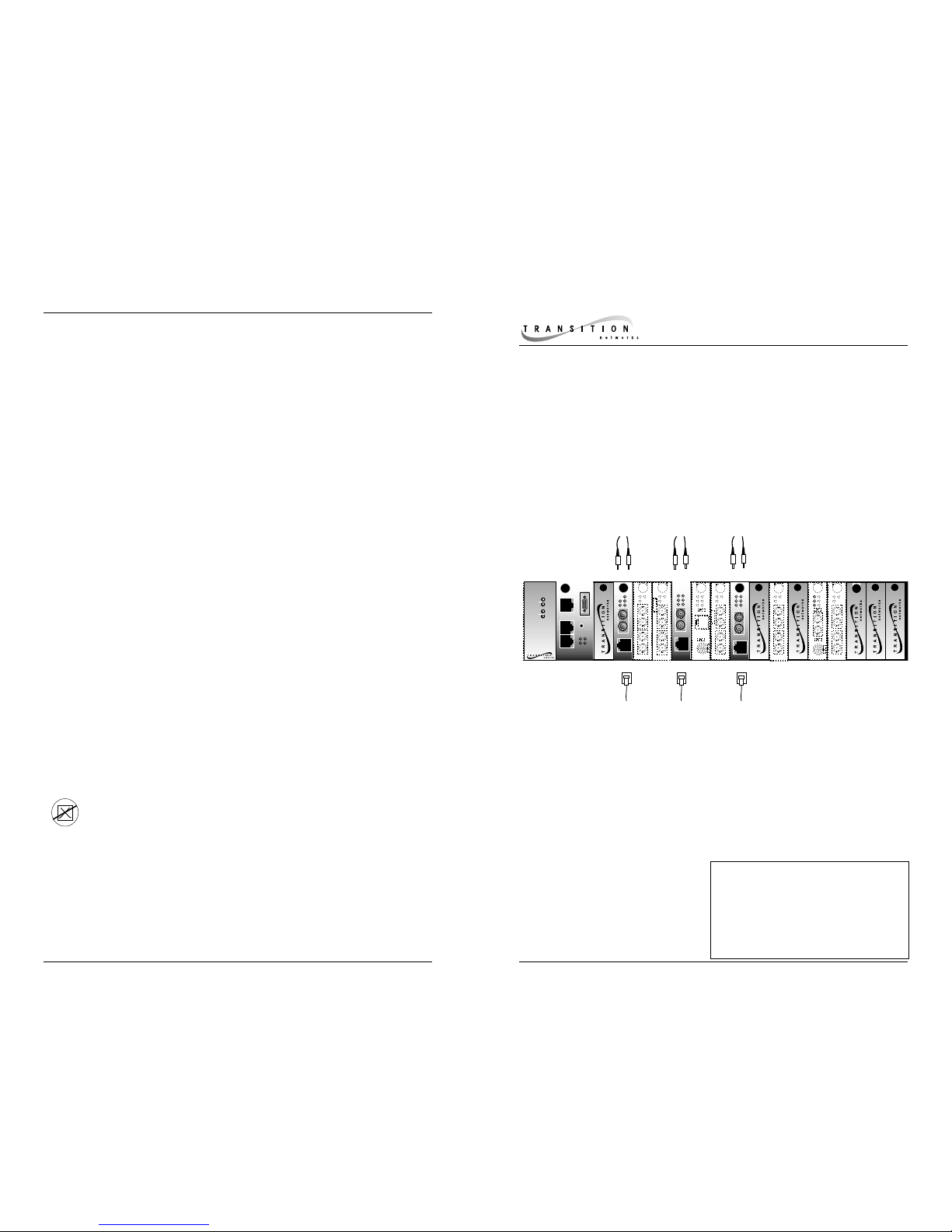
TRANSITION Networks CSETF10xx series Ethernet™ and Fast Ethernet™ media
converters, designed to be installed in a PointSystem™Conversion Center
™
connect 10BASE-T or 100BASE-TX shielded or unshielded twisted-pair copper
cable to 850 nm 10BASE-FL or 850 nm 100BASE-SX multimode fiber-optic cable.
*In the CSETF10xx model designation,10
represents the 10BASE-T/100BASE-TX RJ-45
connector; xx represents the selectable
10BASE-FL/100BASE-SX fiber connector
installed on the media converter.
10BASE-T/100BASE-TX to 10BASE-FL/100BASE-SX
Slide-In-Module Media Converters
CSETF10xx
USER’S GUIDE
10BASE-T
INPORT
MCCM10
MGMT MASTER
RX
TX
LNK
PWR
OUTPORT
RESET
DB-9
12C
12C-1TERM
INIT
CFMFF100
CFMFF100
10BASE-2
CECF100
CECF100
CFMFF100
CFMFF100
0
50
50
‰
CFMFF100
CFMFF100
CETTF100
Link
Link
Alert
Alert
E
D
CETCF100
CETCF100
CFETF110
CFMFF100
CFMFF100
CFMFF100
CFMFF100
LKS
PWR
PWR
LKM
LKS
LKS
PWR
PWR
LKM
LKM
Multimode
Multimode
Singlemode
Singlemode
TX
TX
RX
RX
TX
TX
RX
RX
LKF
PWR
RXF
RXC
LKC
LA
PWR
PWR
RXF
RXC
LNK
LNK
COL
COL
SPD
PWR
FRX
CRX
FLNK
CLNK
RX
TX
10/100TX
RX
TX
10/100SX
CFETF100
SPD
PWR
FRX
CRX
FLNK
CLNK
RX
TX
100BASE-FX
Link
Link
Alert
Alert
E
D
0
50
50
‰
Multimode
Singlemode
TX
RX
TX
RX
LA
PWR
PWR
RXF
RXC
LNK
LNK
COL
COL
LKS
LKS
PWR
PWR
LKM
LKM
10BASE-2
10BASE-FL
10BASE-T
LKS
LKS
PWR
PWR
LKM
LKM
LKS
LKS
PWR
PWR
LKM
LKM
Multimode
Multimode
Singlemode
Singlemode
TX
TX
RX
RX
TX
TX
RX
RX
Multimode
Multimode
Singlemode
Singlemode
TX
TX
RX
RX
TX
TX
RX
RX
Multimode
Multimode
Singlemode
Singlemode
TX
TX
RX
RX
TX
TX
RX
RX
10BASE-T
10BASE-FL
Media
Conversion
Center
Power
In Use
1
Power
In Use
2
CSETF1011
Provides an RJ-45 twisted pair
10BASE-T/100BASE-TX connector
and a set of RX (receive) and TX
(transmit) ST 10BASE-FL/100BASE-
SX connectors to 850 nm
multimode fiber-optic cable.
CSETF1013
Provides an RJ-45 twisted pair
10BASE-T/100BASE-TX connector
and an RX (receive) and TX
(transmit) SC 10BASE-FL/100BASESX connector to 850 nm multimode
fiber-optic cable.
CSETF1018
Provides an RJ-45 twisted pair
10BASE-T/100BASE-TX connector
and an MT-RJ 10BASE-FL/100BASESX connector to 850 nm multimode
fiber-optic cable.
CSETF10xx in the Network . . . . . . . . .2
Installation . . . . . . . . . . . . . . . . . . . .5
Operation . . . . . . . . . . . . . . . . . . . . .6
Fault Isolation and Correction . . . . .8
Cable Specifications . . . . . . . . . . . .10
Technical Specifications . . . . . . . . .11
Compliance Information . . . . . . . . .12
Page 2
CSETF10xx IN THE NETWORK
The CSETF10xx receives and transmits network signals in either fullduplex or half-duplex mode (depending upon the network devices to
which the media converter is attached). Fast Ethernet
™
in full-duplex
mode allows the maximum cable distances shown on these pages. Fast
Ethernet
™
in half-duplex mode requires attention to the 512-bit Rule
(See page 4).
NOTE: Both copper and fiber connections to the CSETF10xx must be at
the same media-speed: 10BASE-T AND 10BASE-FL OR 100BASE-TX AND
100BASE-SX – unless one or both network connections is capable of
auto-negotiation. The CSETF10xx media converter is designed to work
effectively with 10/100 auto-negotiating ports to provide reliable 10
Mb/s or 100 Mb/s fiber links.
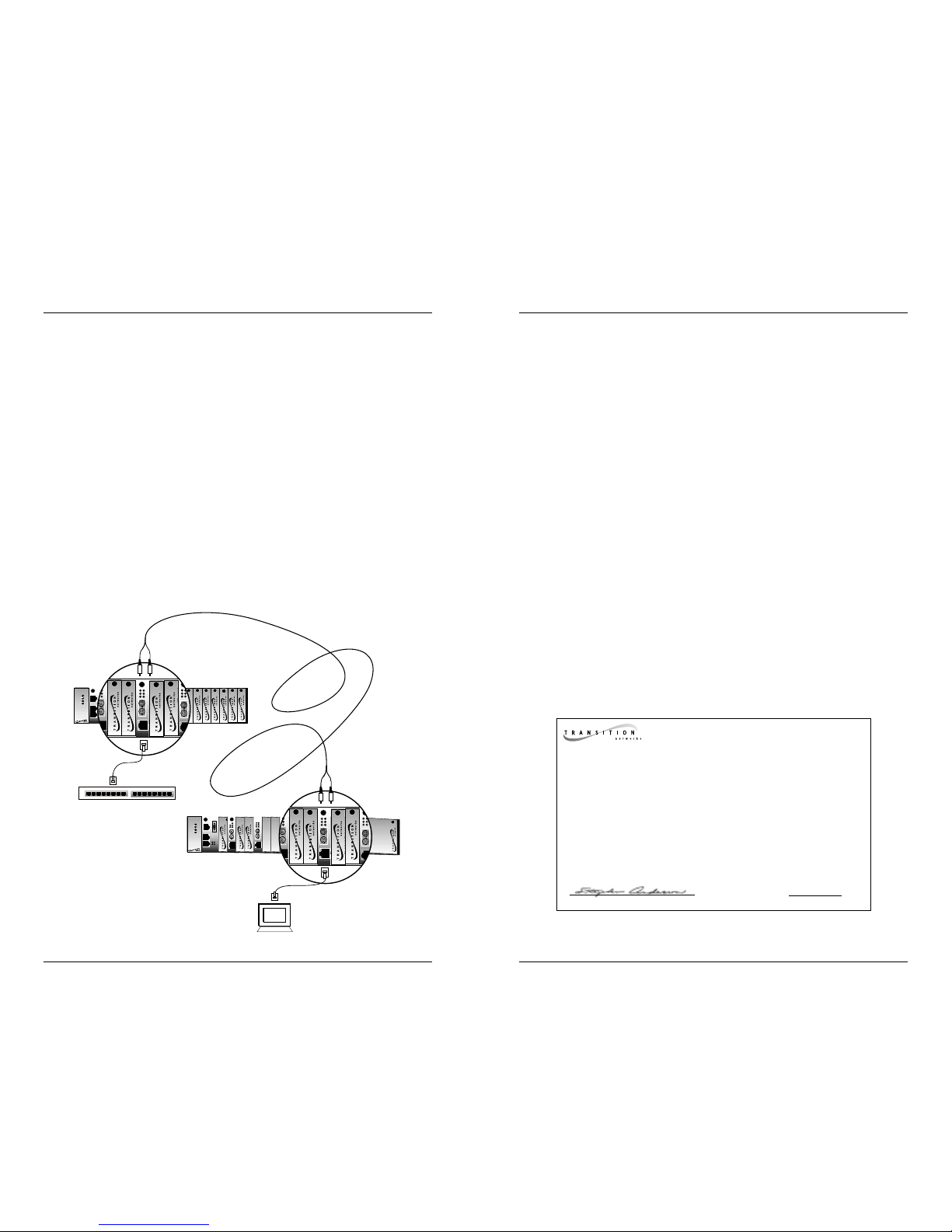
Network Configurations
Install two CSETF10xx series media converters in series to extend, over
fiber, the distance between two 10BASE-T or two 100BASE-TX devices:
TECHNICAL SPECIFICATIONS
Standards IEEE 802.3,
Compliant with pending TIA/EIA-785 specification
Dimensions 3.4" x 0.86" x 5.0" (86mm x 22mm x 127mm)
Weight 8 oz (approximate)
Power Consumption 3.6 watts
Environment Typical Operating Temperature*: 0-50°C (32°to 122°F )
Storage Temperature: -20 to 85°C
Humidity 10-90%, non condensing
Altitude 0-10,000 feet
Warranty Lifetime
*Operating temperature range for this Slide-In-Module depends on the physical
characteristics and the installation configuration of the TRANSITION Networks
chassis in which this Slide-In-Module will be installed. See the User’s Guide for
the chassis in which this Slide-In-Module will be installed for a discussion of
temperature-related installation constraints.
DECLARATION OF CONFORMITY
Name of Mfg: Transition Networks
6475 City West Parkway, Minneapolis MN 55344 USA
Model: CSETF10xx Series Media Converters
Part Number(s): CSETF1011, CSETF1013, CSETF1018
Regulation: EMC Directive 89/336/EEC
Purpose: To declare that the CSETF10xxto which this declaration refers is in
conformity with the following standards.
EMC-CISPR 22: 1985 Class A&B; EN 55022: 1988 Class A&B; EN 50082-1:1992;
EN 60950 A4:1997; IEC 801.2, IEC 801.3, and IEC 801.4; IEC 950
I, the undersigned, hereby declare that the equipment specified above conforms to the
above Directive(s) and Standard(s).
_April 16, 2000_____
Stephen Anderson, Vice-President of Engineering Date
10BASE-T
INPORT
MCCM10
MGMT MASTER
RX
TX
LNK
PWR
OUTPORT
RESET
DB-9
12C
12C-1TERM
INIT
CETTF100
CFETF110
LKF
PWR
RXF
RXC
LKC
SPD
PWR
FRX
CRX
FLNK
CLNK
RX
TX
10/100TX
RX
TX
10/100SX
CFETF100
SPD
PWR
FRX
CRX
FLNK
CLNK
RX
TX
100BASE-FX
10BASE-T
10BASE-FL
Media
Conversion
Center
Power
In Use
1
Power
In Use
2
PWR
LKC
SPD
FRX
CRX
10/100TX
RX
TX
10/100SX
SPD
PWR
FRX
CRX
FLNK
CLNK
RX
TX
100BASE-FX
10BASE-T
INPORT
MCCM10
MGMT MASTER
RX
TX
LNK
PWR
OUTPORT
RESET
DB-9
12C
12C-1TERM
INIT
CETTF100
CFETF110
LKF
PWR
RXF
RXC
LKC
SPD
PWR
FRX
CRX
FLNK
CLNK
RX
TX
10/100TX
RX
TX
10/100SX
CFETF100
SPD
PWR
FRX
CRX
FLNK
CLNK
RX
TX
100BASE-FX
10BASE-T
10BASE-FL
Media
Conversion
Center
Power
In Use
1
Power
In Use
2
PWR
LKC
SPD
FRX
CRX
10/100TX
RX
TX
10/100SX
SPD
PWR
FRX
CRX
FLNK
CLNK
RX
TX
100BASE-FX
Page 3

CABLE SPECIFICATIONS
The physical characteristics of the media cable must meet or exceed IEEE 802.3
specifications.
Fiber Cable
MULTIMODE
Fiber Optic Cable Recommended: 62.5 / 125 µm multimode fiber
Optional: 100 / 140 µm multimode fiber
85 / 125 µm multimode fiber
50 / 125 µm multimode fiber
Wavelength : 850 nM
Attenuation: ≤3.75 dB/ 1 kilometer @ 850 nM
Fiber-optic Transmitter Power: min: -16.0 dBm max: -10.0 dBm
Fiber-optic Receiver Sensitivity: min: -29.50 dBm max: -7.2 dBm
Link Budget 13.5 dB
Typical Maximum Cable Distance:* Full-duplex 300 meters @ 100 Mb/s
2 kilometers @ 10 Mb/s
Half Duplex: See page 4
*Actual distance dependent upon physical characteristics of network installation.
Copper Cable
Category 5 twisted-pair copper wire is required. Either shielded twisted-pair
(STP) or unshielded twisted-pair (UTP) can be used. DO NOT USE FLAT OR
SILVER SATIN WIRE.
CATEGORY 5:
Gauge 24 to 22 AWG
Attenuation 22.0 dB /100m @ 100 MHz
Maximum Cable Distance: 100 meters
The two active pairs in an Ethernet™ network are pins 1 & 2 and pins 3 & 6. Use
only dedicated wire pairs (such as blue/white & white/blue, orange/white &
white/orange) for the active pins.
Twisted pair connection requires two active pairs configured as straight through or
crossover, as shown:
RJ-45 Pin-out: Pin 1=TD+, Pin 2=TD-, Pin 3=RD+, Pin 6=RD-
Use the the CSETF10xx media converter to connect a 10BASE-T or
100BASE-TX terminal device and a 10BASE-FL or 100BASE-SX (half-duplex
only) hub, switch, or router:
Or use the the CSETF10xx media converter to connect a 10BASE-T or
100BASE-TX hub, switch, or router and a 10BASE-FL or 100BASE-SX terminal
device:
Crossover
1
2
3
6
Straight Through
Twisted Pair #1
Twisted Pair #1
Twisted Pair #2
Twisted Pair #2
1
2
3
6
1
2
3
6
1
2
3
6
10BASE-T
INPORT
MCCM10
MGMT MASTER
RX
TX
LNK
PWR
OUTPORT
RESET
DB-9
12C
12C-1TERM
INIT
CETTF100
CFETF110
LKF
PWR
RXF
RXC
LKC
SPD
PWR
FRX
CRX
FLNK
CLNK
RX
TX
10/100TX
RX
TX
10/100SX
CFETF100
SPD
PWR
FRX
CRX
FLNK
CLNK
RX
TX
100BASE-FX
10BASE-T
10BASE-FL
Media
Conversion
Center
Power
In Use
1
Power
In Use
2
PWR
LKC
SPD
FRX
CRX
10/100TX
RX
TX
10/100SX
SPD
PWR
FRX
CRX
FLNK
CLNK
RX
TX
100BASE-FX
10BASE-T
INPORT
MCCM10
MGMT MASTER
RX
TX
LNK
PWR
OUTPORT
RESET
DB-9
12C
12C-1TERM
INIT
CETTF100
CFETF110
LKF
PWR
RXF
RXC
LKC
SPD
PWR
FRX
CRX
FLNK
CLNK
RX
TX
10/100TX
RX
TX
10/100SX
CFETF100
SPD
PWR
FRX
CRX
FLNK
CLNK
RX
TX
100BASE-FX
10BASE-T
10BASE-FL
Media
Conversion
Center
Power
In Use
1
Power
In Use
2
PWR
LKC
SPD
FRX
CRX
10/100TX
RX
TX
10/100SX
SPD
PWR
FRX
CRX
FLNK
CLNK
RX
TX
100BASE-FX
Page 4

CSETF10XX IN THE NETWORK (continued)
Media Converter in Full-Duplex Network
In a full-duplex network, maximum cable lengths are determined by the
cables used. See page 10 for cable specifications.
NOTE: THE 512-BIT RULE DESCRIBED BELOW DOES NOT APPLY IN A
FULL-DUPLEX NETWORK.
Media Converter in Half-Duplex Network
NOTE: The 512-Bit Rule applies separately to each collision domain.
USING THE 512-BIT RULE
In a half-duplex network, maximum cable lengths are determined by the
round trip delay limitations of each Fast Ethernet
™ collision domain.
(Switches and routers divide the network into separate Ethernet™ collision
domains.) The 512-Bit Rule determines maximum distances by calculating
the collision domain round-trip delay in bit-times.
To calculate a collision domain
round-trip delay, find the longest path
between any two terminal devices in
the collision domain. Calculate the
round trip delay by multiplying the
length of the cable (in meters) by the
delay per meter (in bit-times – BT),
then take the sum of all cable delays plus DTE, repeater, and media converter
delays. If the result is less than or equal to 512 bit-times, the path is good.
5. Is the RXC LED flashing?
NO
• If there IS NO ACTIVITY on the 10BASE-T/100BASE-TX port,
proceed to step 6.
• If there IS ACTIVITY on the 10BASE-T/100BASE-TX port, disconnect
and reconnect the 10BASE-T/100BASE-TX cable to restart the
initialization process.
• Restart the workstation to restart the initialization process.
• Contact Technical Support: (800) 260-1312.
YES
• Proceed to step 6.
6. Is the RXF LED flashing?
NO
• If there IS NO ACTIVITY on the 10BASE-FL/100BASE-SX port,
continue below
• If there IS ACTIVITY on the 10BASE-FL/100BASE-SX port,
disconnect and reconnect the 10BASE-FL/100BASE-SX cable to
restart the initialization process.
• Verify that TX and RX cables on media converter are connected to
RX and TX ports, respectively, on other device.
• Restart the workstation to restart the initialization process.
• Contact Technical Support: (800) 260-1312.
YES
• Contact Technical Support: (800) 260-1312.
Class I repeater 140 BT
Class II repeater 92 BT
DTE (PC, switch, router) 50 BT
CSETF10xx 12 BT
1 meter CAT.5 TP cable 1.11 BT
1 meter fiber cable 1 BT
Fast Ethernet switch 50 BT
10 meters TP
@ 1.11BT/meter
= 11.1BT
10 meters TP
@ 1.11BT/meter
= 11.1BT
= 12BT
DTE= 50BT
Half-Duplex Collision Domain
Half-Duplex Collision Domain
200 meters fiber
@ 1.0 BT/meter
= 200BT
DTE= 50BT
50.00BT
+11.10BT
+12.00BT
+200.00BT
+12.00BT
+11.10BT
+50.00BT
__________
_
= 346.20BT
DTE= 50BT
10 meters TP
@ 1.11BT/meter
= 11.1BT
150 meters fiber
@ 1.0 BT/meter
= 150BT
10 meters TP
@ 1.11BT/meter
= 11.1BT
Class I
Hub
= 140BT
50.00BT
+11.10BT
+140.00BT
+150.00BT
+12.00BT
+11.10BT
+50.00BT
__________
_
= 424.20BT
Switch/
Router
= 50BT
= 12BT
Full-Duplex - NO Collision Domain
= 12BT
= 12BT
Page 5

FAULT ISOLATION and CORRECTION
If the media converter fails, isolate and correct the fault by determining the
answers to the following questions and then taking the indicated action:
1. Is the P(o)W(e)R LED on the media converter illuminated?
NO
• Is the media converter inserted properly into the chassis?
• Is the power cord properly installed in the chassis and in the
grounded AC outlet?
• Does the grounded AC outlet provide power?
• Contact Technical Support: (800) 260-1312.
YES
• Proceed to step 2.
2. Is the LKC LED illuminated?
NO
• Check twisted pair cables for proper connection.
• Contact Technical Support: (800) 260-1312.
YES
• Proceed to step 3.
3. Is the LKF LED illuminated?
NO
• Check fiber cables for proper connection.
• Verify that TX and RX cables on media converter are connected to
RX and TX ports, respectively, on other device.
• Contact Technical Support: (800) 260-1312.
YES
• Proceed to step 4.
4. Is the 100 LED illuminated?
NO
• The media converter has selected 10 Mb/s operation. If this is NOT
the correct speed, disconnect and reconnect the 10/100BASE-TX
cable to restart the initialization process.
• Proceed to step 5.
YES - Slowly flashing
• The media converter is selecting between 10 Mb/s and 100 Mb/s
speed OR one or both of the links is down. IF PERSISTENT,
disconnect and reconnect either cable to restart the initialization
process.
• Proceed to step 5.
YES
• The media converter has selected 100 Mb/s operation. If this is NOT
the correct speed, disconnect and reconnect the 10/100BASE-TX
cable to restart the initialization process.
• Proceed to step 5.
INSTALLATION
CAUTION: Wear a grounding device and observe electrostatic discharge
precautions when setting switch and when installing Media Converter Slide-inModule in the Media Conversion Center. Failure to observe this caution could
result in damage to, and subsequent failure of, the Media Converter Slide-inModule.
Install Slide-In-Module in PointSystem™Chassis
CAUTION: Any Slide-in-Module installation slot in which a Media Converter
Slide-in-Module is NOT installed MUST have a protective plate instead.
Failure to observe this caution will void Class A and/or Class B compliance.
NOTE: Install Media Converter Slide-in-Modules in any slot, in any order.
1. Carefully slide Media Converter Slide-in-Module into installation slot,
aligning Media Converter Slide-in-Module with installation guides.
NOTE: Ensure that Slide-in-Module is firmly seated against backplane.
2. Secure Slide-in-Module by securing panel fastener screw (attached to
Slide-in-Module) to chassis front.
3. Install protective plate at ANY Slide-in-Module installation slot in which
a Media Converter Slide-in-Module is not installed by securing attached
protective plate panel fastener screw to chassis front.
Install Cable
COPPER
NOTE: AutoCross™ allows the use of either straight-through or crossover
configuration cables.
1. Locate or build 10BASE-T-compliant or 100BASE-TX-compliant
cables with male RJ-45 connectors installed at both ends.
2. Connect RJ-45 connector at one end of cable to media converter
RJ-45 port connector.
3. Connect RJ-45 connector at other end of cable to 10BASE-T-
compliant or 100BASE-TX-compliant device RJ-45 port connector.
FIBER
1. Locate or build 10/100BASE-SX-compliant fiber cable with male
two-stranded TX to RX connectors installed at both ends.
2. Connect male TX and RX cable connectors at one end of cable to
TX and RX female connectors, respectively, on media converter.
3. Connect male TX and RX cable connectors at other end of cable to
10/100BASE-SX-compliant device RX and TX connectors, respectively.
TX
RX
TX
RX
Page 6

INSTALLATION (continued)
Power the Slide-In-Module
NOTE: The Slide-In-Module is powered through the Conversion
Center
™
.
OPERATION
Using Status LEDs
Use the status LEDs to monitor media converter operation in the network.
100 (Speed) Dark LED indicates 10 Mb/s operation.
Slow blinking LED indicates speed is
not yet selected.
Fast blinking LED indicates 100 Mb/s.
PWR (Power) Steady LED indicates
connection to external AC power.
RXF (Fiber receive) Flashing LED indicates
reception of data on fiber link.
LKF (Fiber link) Steady LED indicates fiber link connection.
Dark LED indicates lack of power OR downed link.
RXC (Receive -
copper) Flashing LED indicates data reception on
copper link.
LKC (Copper link) Steady LED indicates copper link connection.
Dark LED indicates lack of power OR downed link.
Using SNMP*
Use SNMP at an attached terminal or at a remote location to:
• Monitor media converter by monitoring:
Media Converter Power
Copper Link Status
Fiber Link Status
Copper Receive Status
Fiber Receive Status
Hardware Switch settings
Media Converter Speed
• Enter network commands that:
Enable/disable AutoCross
™
Power Down Media Converter.
*See the on-line documentation that comes with TRANSITION Networks
FocalPoint
™
software for direction.
Using AutoCross
™
*
The AutoCross™ feature allows either straight-through (MDI) or crossover
(MDI-X) cables to be used when connecting to 10BASE-T or to 100BASE-TX
devices, such as hubs, transceivers, or network interface cards (NICs).
AutoCross
™
determines the characteristics of the cable connection and
automatically configures the unit to link up, regardless of the cable
configuration.
*Requires no operator intervention.
Using Auto-negotiation**
The CSETF10xx series media converter auto-negotiation feature allows the
media converter to be used with 10BASE-T, 100BASE-TX, 10BASE-FL and
100BASE-SX ports. Using auto-negotiation, the media converter brings up the
copper and fiber links in the highest speed and mode possible for ALL the
attached network devices.
NOTE: The CSETF10xx series media converter does NOT support rate
conversion between 10Mb/s and 100Mb/s network devices.
**Requires no operator intervention.
Using LinkAlert™
The CSETF10xx series media converter LinkAlert™ feature allows the media
converter to pass 10BASE-T/100BASE-TX-side link faults over the link to the
10BASE-T/100BASE-SX side and to pass 10BASE-FL/100BASE-SX-side link
faults over the link to the 10BASE-FL/100BASE-TX side.
If the CSETF10xx media converter does not detect a good link on the
10BASE-T/100BASE-TX side, the CSETF10xx disables all transmission
(including active-idle) on the 10BASE-FL/100BASE-SX side.
10/100BASE-TX
Device
Media Converter
LINK FAULT INDICATION
10/100BASE-SX
Device
PWR
RXF
LKF
100
 Loading...