

Page 1
MEDIA CONVERTER TECHNICAL SPECIFICATIONS
Host Connection IBM® S/3x (System 34, 36, 38) host, AS/400™
host or 5x94 remote controller
Case dimensions 4.75" x 3.0" x 1.0" (119mm x 76mm x 25mm)
Shipping Weight 2 pounds (0.9 kilograms)
Environment Temperature: 0-50°C (32-122°F)
Humidity 10-90%, non condensing
Altitude 0-10,000 feet
Warranty Five years
CAUTION: RJ connectors are NOT INTENDED FOR CONNECTION TO THE
PUBLIC TELEPHONE NETWORK. Failure to observe this caution could result in
damage to the public telephone network.
Compliance Information
UL Listed
C-UL Listed (Canada)
CISPR/EN55022 Class A
FCC Regulations
This equipment has been tested and found to comply with the limits for a class A digital device, pursuant
to part 15 of the FCC rules. These limits are designed to provide reasonable protection against harmful
interference when the equipment is operated in a commercial environment. This equipment generates,
uses, and can radiate radio frequency energy and, if not installed and used in accordance with the
instruction manual, may cause harmful interference to radio communications. Operation of this
equipment in a residential area is likely to cause harmful interference, in which case the user will be
required to correct the interference at the user’s own expense.
Canadian Regulations
This digital apparatus does not exceed the Class A limits for radio noise for digital apparatus set out on
the radio interference regulations of the Canadian Department of Communications.
European Regulations
Warning
This is a Class A product. In a domestic environment this product may cause radio interference in which
case the user may be required to take adequate measures.
Copyright Restrictions
© 1998, 1999 TRANSITION Networks.
All rights reserved. No part of this work may be reproduced or used in any form or by any means –
graphic, electronic, or mechanical – without written permission from TRANSITION Networks.
Trademark Notice
All registered trademarks and trademarks are the property of their respective owners. 33092.B
Der Anschluss dieses Gerätes an ein öffentlickes Telekommunikationsnetz in den EG-Mitgliedstaaten
verstösst gegen die jeweligen einzelstaatlichen Gesetze zur Anwendung der Richtlinie 91/263/EWG zur
Angleichung der Rechtsvorschriften der Mitgliedstaaten über Telekommunikationsendeinrichtungen
einschliesslich der gegenseitigen Anerkennung ihrer Konformität.
The TRANSITION Networks 5250 Copper to Fiber C/PS-CF-01 series media
converters, designed to be installed in the E-MCC-1600 chassis and to
support all IBM®5250 compliant devices (including devices operating at a
non-standard rates), extends the signal distance of an AS/400™ or S/3x host
computer or a 5x94 remote controller to terminal equipment over twistedpair copper and over multimode or singlemode fiber. C/PS-CF-01 series
media converters allow twisted-pair copper network extension distances up
to 1524 meters (762 meters each connection on two media converters) AND
fiber network extension distances up to 2 kilometers on multimode fiber and
up to 8 kilometers on singlemode fiber.*
Minneapolis, MN 55344 USA
5250 Copper/Fiber
Slide-In-Module Media Converters
C/PS-CF-01, C/PS-CF-01(SC), C/PS-CF-01(SM)
USER’S GUIDE
C/PS-CF-01
Provides an RJ-45 twisted-pair
connector to copper cable and a set of
RX (receive) and TX (transmit) ST
connectors to multimode fiber-optic
cable.
C/PS-CF-01(SC)
Provides an RJ-45 twisted-pair
connector to copper cable and an RX
(receive) and TX (transmit) SC
connector to multimode fiber-optic
cable.
C/PS-CF-01(SM)
Provides an RJ-45 twisted-pair
connector to copper cable and an RX
(receive) ST and TX (transmit) SC
connector to singlemode fiber-optic
cable.
Multimode Fiber Singlemode Fiber
C/PS-CF-01
C/PS-CF-01(SC)
C/PS-CF-01(SM)
RX
TX
Fiber
UTP/STP
Power
Power Modules
Media
Conversion
Center
E-MCC-1600
Power
In Use
Power
In Use
1
2
Management
Module
Power
Link
TX
RX
RX
TX
Fiber
UTP/STP
Power
RX
TX
Fiber
UTP/STP
Power
Twisted-Pair Copper
*See note at top of pages 4 & 5.
STATUS LEDS
Power Steady green LED indicates
connection to external AC
power.
UTP/STP Blinking green LED
indicates network traffic on unshielded or shielded twisted-pair
link.
Fiber Blinking green LED indicates network traffic on fiber link.
10BASE-T
RX
TX
Fiber
UTP/STP
Power
Page 2

Installation NOTES
To install the C/PS-CF-01 series media converter:
1. Install the C/PS-CF-01 in the E-MCC-1600 chassis.
NOTE: Media Converter Slide-in-Modules can be installed in any
installation slot, in any order.
• Remove Media Converter Slide-in-Module protective plate
from selected installation slot by removing two screws that
secure plate to front of E-MCC-1600. Retain one installation
screw.
• Carefully slide Media Converter Slide-in-Module into
installation slot, aligning Media Converter Slide-in-Module
with installation guides.
NOTE: Ensure that the Media Converter Slide-in-Module is firmly
seated against the backplane.
• Secure Slide-in-Module by installing retained installation
screw.
2. Connect host signal to C/PS-CF-01 media converter.
• Locate or build twisted-pair cables that are compliant with
cable specifications (See page 7) and with male RJ-45 plug
connectors installed at both cable ends.
NOTE: Install TRANSITION Networks balun part number: 3-4554
between RJ-45 cable and Twinax connector.
• Install balun at host Twinax connector.
•. Connect male RJ-45 plug connector at one end of twisted pair
cable to balun on host Twinax connector.
• Connect male RJ-45 plug connector at other end of twisted
pair cable to female RJ-45 connector on C/PS-CF-01 media
converter.
3. Connect C/PS-CF-01 media converter to second C/PS-CF-01 media
converter*:
• Locate or build fiber cable that conform to cable
specifications (See page 7) and with male fiber connectors
installed at both ends.
CABLE SPECIFICATIONS
The physical characteristics of the cable must meet or exceed the following:
FIBER CABLE
MULTIMODE
Fiber Optic Cable Recommended: 62.5 / 125 µm multimode fiber
Fiber Optic Transmitter Power: min: -19.0
dBm max: -14.0 dBm
Fiber Optic Receiver Sensitivity: min: -32.5
dBm max: -14.0 dBm
Wavelength: 850nM
Bit error rate: ≤10
-9
Maximum Cable Distance: 2 kilometers
SINGLEMODE
Fiber Optic Cable Recommended: 9 µm singlemode fiber
Fiber Optic Transmitter Power: min: -27.0
dBm
max: -17.0 dBm
Fiber Optic Receiver Sensitivity: min: -32.5 dBm max: -13.0 dBm
Wavelength: 1300nM
Bit error rate: ≤10
-9
Maximum Cable Distance: 8 kilometers
TWISTED PAIR CABLE AND CONNECTOR
Category 3 wire or better is required; category 5 wire is recommended. Either
shielded twisted pair (STP) or unshielded twisted pair (UTP) can be used. DO
NOT USE FLAT OR SILVER SATIN WIRE.
Category 3:
Gauge 24 to 22 AWG
Attenuation 28 dB/1000’ @ 10 MHz
Differential Characteristic Impedance 100 Ω ±10% @ 10 MHz
Category 5:
Gauge 24 to 22 AWG
Attenuation 20 dB/1000’ @ 10 MHz
Differential Characteristic Impedance 100 Ω ±10% @ 10 MHz
Minimum UTP/STP Cable Distance: 7.6 meters (25 feet)
Maximum UTP/STP Cable Distance:
762 meters (2500 feet)
Connector:
RJ-45 connectors with active
pair pins 4 & 5.
7
2
All cable connections to the C/PS-CF-01 MUST be
AT LEAST 7.6 meters (25 feet) in length.
C/PS-CF-01
3
4
5
6
RJ-45
connector
Straight Through Cable
3
4
5
6
RJ-45
connector
NOTE: The active pair in a twisted-pair
copper 5250-compliant network are pins
4 & 5. Use only dedicated wire pairs
(such as blue/white & white/blue,
orange/white & white/orange) for the
active pins.
Page 3

TROUBLESHOOTING SUGGESTIONS
NOTE: Refer to status LED description on last page.
If a Media Converter fails, ask the following questions:
1. Is the Power LED on the media converter illuminated?
NO
• Is the power adapter the proper voltage and cycle frequency
for the AC outlet? NOTE: Refer to the “Power Supply
Requirements” on the back page.
• Is the power adapter properly installed in the media converter
and in the outlet?
• Contact Technical Support: (800) 260-1312/(800) LANWANS.
YES
• Proceed to step 2.
2. Is the UTP/STP LED illuminated?
NO
• Check twisted pair cables for proper connection.
• Check RJ-45 connector for correct twisted pair cable
configuration.
• Contact Technical Support: (800) 260-1312/(800) LANWANS.
YES
• Proceed to step 3.
3. Is the Fiber LED illuminated?
NO
• Check fiber cables for proper connection.
• Verify that TX and RX cables on media converter are
connected to RX and TX ports, respectively, on other device.
• Contact Technical Support: (800) 260-1312/(800) LANWANS.
YES
• Contact Technical Support: (800) 260-1312/(800) LANWANS.
• Connect one end of one first fiber cable to C/PS-CF-01 media
converter TX connector.
• Connect other end of that fiber cable to second C/PS-CF-01
media converter RX connector or to PowerStar™ IV fiber SIC
card.
• Connect one end of second fiber cable to C/PS-CF-01 media
converter RX connector.
• .Connect other end of that fiber cable to C/PS-CF-01 media
converter TX connector or to PowerStar™ IV fiber SIC card.
*Or optionally connect directly to PowerStar™ IV fiber SIC card.
4. Connect second C/PS-CF-01 media converterto terminal equipment
through copper cable.
UTP to RJ-45 Connector:
If connecting to RJ-45 connector on terminal equipment (as on
front of PowerStar™ III or PowerStar™ IV):
• Connect male RJ-45 plug connector to female RJ-45 connector
marked “link” on terminal equipment.
UTP to Twinax Connector:
If connecting to twinax connector on terminal equipment (as on
back of PowerStar™ III or on PowerStar™ IV with Twinax SIC):
NOTE: Install TRANSITION Networks balun part number: 3-4554
between RJ-45 cable and Twinax connector.
• Install balun at terminal equipment Twinax connector.
• Connect male RJ-45 plug connector to balun.
5. Connect C/PS-CF-01(s)to power.
• Locate correct power supply adapter for site installation. (See
back page.)
• Connect C/PS-CF-01 power connector at end of power supply
adapter cord to C/PS-CF-01 power receptacle.
• Connect 2-prong or 3-prong external power connector on
other end of power supply adapter cord to external AC power.
3
6
C/PS-CF-01
Page 4

Multimode Fiber Singlemode Fiber
C/PS-CF-01
C/PS-CF-01(SC)
C/PS-CF-01(SM)
RX
TX
Fiber
UTP/STP
Power
Power Modules
Media
Conversion
Center
E-MCC-1600
Power
In Use
Power
In Use
1
2
Management
Module
Power
Link
TX
RX
RX
TX
Fiber
UTP/STP
Power
RX
TX
Fiber
UTP/STP
Power
Twisted-Pair Copper
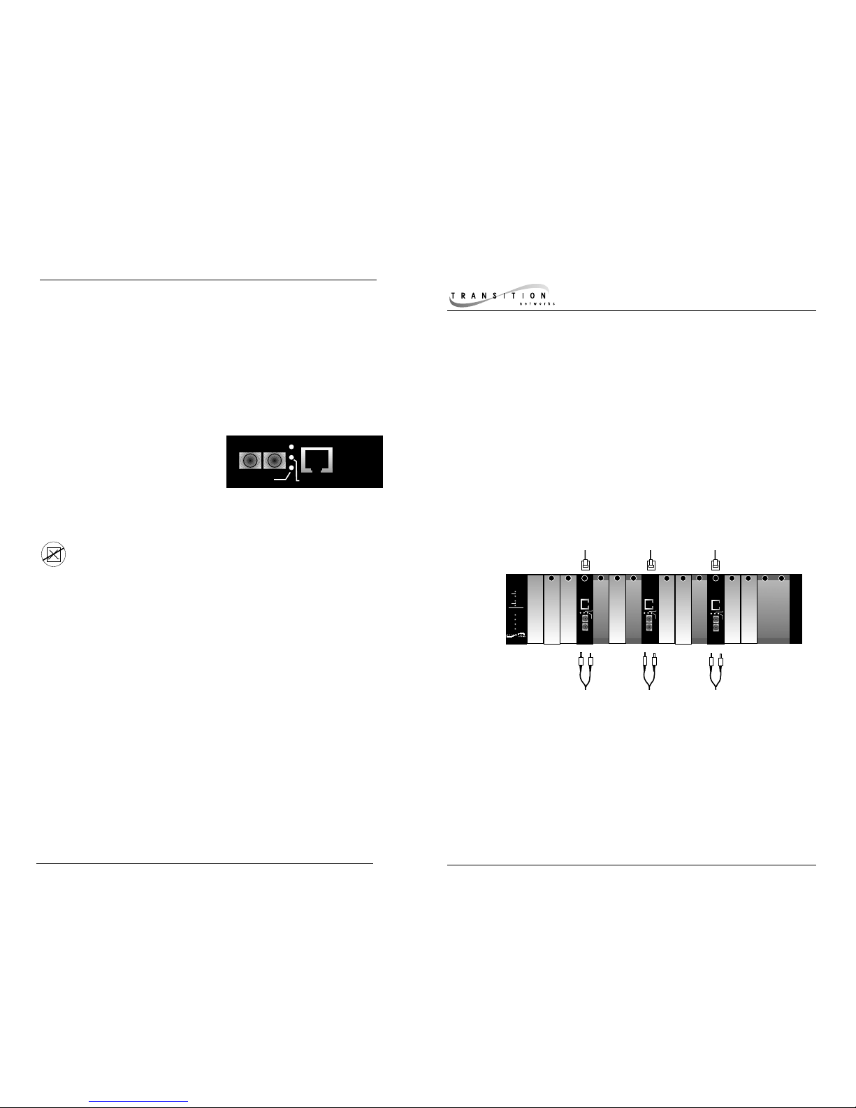
C/PS-CF-01 series media converters can be installed:
In pairs that connect, through copper cable, RJ-45 connectors, and baluns, then
through fiber, and then through copper cable and RJ-45 connectors, a 5250compliant host with a PowerStar™ III or PowerStar™ IV hub.
As a single media converter that extends network distance, through copper cable,
an RJ-45 connector and balun AND through fiber, between a 5250-compliant host
and a PowerStar™ IV hub that has an installed fiber SIC card.
In pairs that connect, through copper cable, RJ-45 connectors, and baluns AND
through fiber, a 5250-compliant host and the Twinax connector at the back of a
PowerStar™ III hub OR a PowerStar™ IV hub that has an installed Twinax SIC card.
MEDIA CONVERTERS in the NETWORK
C/PS-CF-01
1
2
3
NOTE: DEVICES INSTALLED AT MAXIMUM DISTANCES MAY NOT
FUNCTION RELIABLY DUE TO LIMITATIONS IMPOSED BY HOST
TIME-OUTS AND/OR BY TERMINAL EQUIPMENT TIME-OUTS.
 Loading...