

Transition Networks CEMTF1014-100, CEMTF1029-101, CEMTF1015-100, CEMTF1029-103, CEMTF1029-100 User Manual
...Page 1
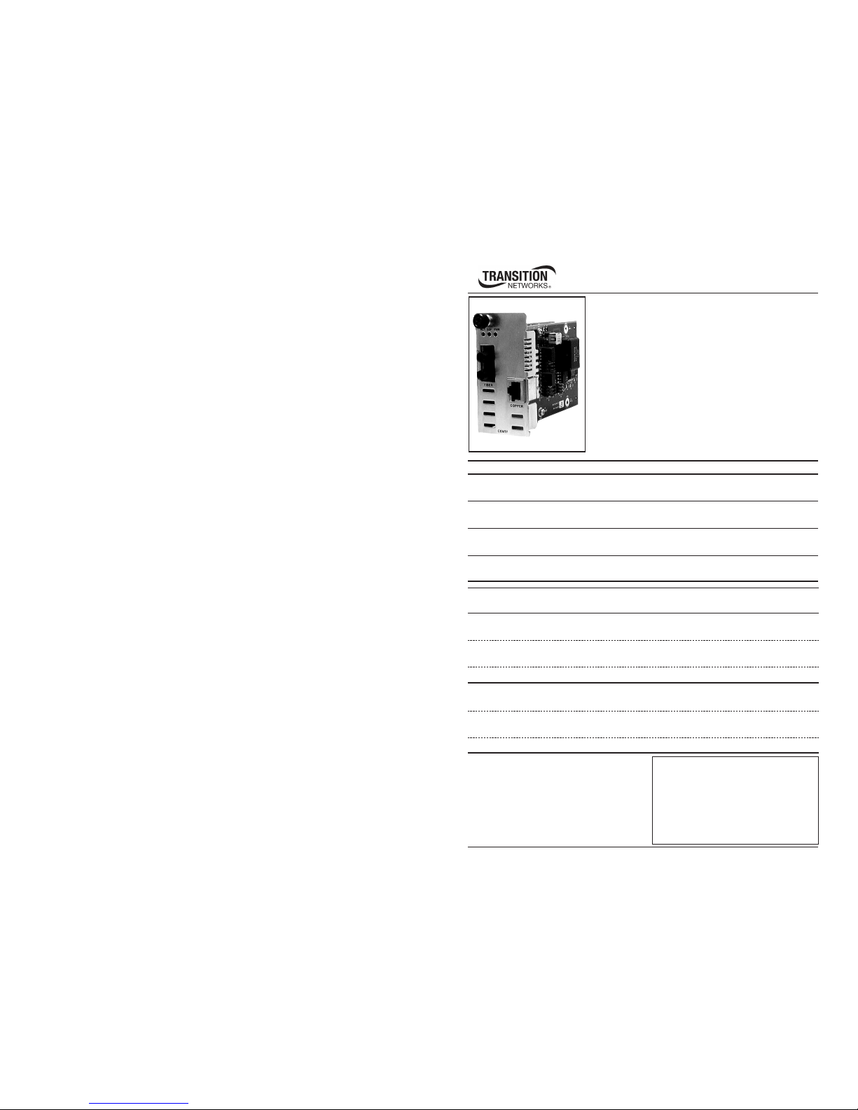
User’s Guide
CEMTF10xx-10x
Slide-in-Module Device
E&M 2/4 Wire to Fiber
Transition Networks CEMTF10xx-10x series E&M 2/4
Wire-to-Fiber Device connects central-office voice
grade signals to distant PBX (Private Branch eXchange)
equipment utilizing E&M signaling. The Device provides
complete electrical isolation for 2- or 4-wire voice path
cable in areas of high electrical noise or where high
security is required.
Product Number Port One - Copper Port Two - Fiber-Optic
CEMTF1011-100 RJ-45
5 km (3.1 miles)*
ST, 1300 nm multimode
2 km (1.24 miles)*
CEMTF1013-100 RJ-45
5 km (3.1 miles)*
SC, 1300 nm multimode
2 km (1.24 miles)*
CEMTF1014-100 RJ-45
5 km (3.1 miles)*
SC, 1310 nm single mode
20 km (12.4 miles)*
CEMTF1015-100 RJ-45
5 km (3.1 miles)*
SC, 1310 nm single mode
40 km (24.9 miles)*
* Typical maximum cable distance. Actual
distance is dependent upon the physical
characteristics of the network
installation.
CEMTF10xx-10x in the Network . . .2
Installation . . . . . . . . . . . . . . . . . . . . .3
Operation . . . . . . . . . . . . . . . . . . . .13
Cable Specifications . . . . . . . . . . . . .15
Technical Specifications . . . . . . . . . .16
Troubleshooting . . . . . . . . . . . . . . . .17
Compliance Information . . . . . . . . .18
Part Number Port One - Copper Port Two - Fiber-Optic
single-fiber single mode
CEMTF1029-100 RJ-45
5 km (3.1 miles)*
SC, 1310 (TX) / 1550 (RX) nm
20 km (12.4 miles)*
CEMTF1029-101 RJ-45
5 km (3.1 miles)*
SC, 1550 (TX) / 1310 (RX) nm
20 km (12.4 miles)*
CEMTF1029-102 RJ-45
5 km (3.1 miles)*
SC, 1310 (TX) / 1550 (RX) nm
40 km (24.8 miles)*
CEMTF1029-103 RJ-45
5 km (3.1 miles)*
SC, 1550 (TX) / 1310 (RX) nm
40 km (24.8 miles)*
CEMTF1029-102 and -103 are intended to be installed in the same network.
CEMTF1029-100 and -101 are intended to be installed in the same network.
Page 2

2
CEMTF10xx-10x
24-Hour Technical Support: 1-800-260-1312 -- International: 00-1-952-941-7600
CEMTF10xx-10x in the Network
Install two CEMTF10xx-10x series Devices in series to extend, over fiber, the distance
between two voice path communication devices. An E&M signal is used to
communicate between a CO (telephone company C
entral Office) device and a PBX
(Private Branch eXchange) device. An RJ-45 female connector provides the electrical
interface between the Device and the communication device.
A fiber optic cable extends the distance between the two devices by up to 40 Km.
The fiber optic cable is not susceptible to lightning impulse noise and, since signal
ground is not carried over the link, the signal is not affected by elevated ground
potential between locations.
(These models are intended for on-premise applications. Therefore, no provision for sealing
the currents is provided.)
In order to transmit the voice signal from one communication device to the other, the
Device connected to the CO device is configured to emulate the PBX device.
Conversely, the Device connected to the PBX device is configured to emulate the CO
device.
CEMTF10xx-100
Configured to emulate
the PBX device ("Side A")
CEMTF10xx-100
Configured to emulate
the CO device ("Side B")
PBX device
("Side A"
)
CO device
("Side B")
“Side A” and “Side B”
The term “Side A” is used to refer to a PBX device and “Side B” is used to refer to a
CO device. Therefore, the network described above contains the following
components
• A CO device (“Side B”).
• A CEMTF10xx-10x configured to emulate the PBX device (“Side A”).
• A CEMTF10xx-10x configured to emulate the CO device (“Side B”).
• A PBX device (“Side A”).
The table at the top of page 3 lists the common terminology used to describe “Side
A” and “Side B” of an E&M interface (i.e, the interface between the communication
device and the CEMTF10xx-10x Device).
3
techsupport@transition.com -- Click the “Transition Now” link for a live Web chat.
PBX Device (Side A) CO Device (Side B)
ANSI Customer Installation (CI) Network (N)
Telicordia Connecting Equipment DLC System
Lucent Trunk Side Signaling Side
Installation
CAUTION: Wear a grounding device and observe electrostatic discharge precautions
when setting the jumpers and when installing the CEMTF10xx-10x Device. Failure to
observe this caution could result in damage to, and subsequent failure of, the Device
slide-in-module.
Setting the Jumpers
The CEMTF10xx-10x Device has five jumpers that are located on the circuit
board. One jumper (J2) is used to set the Device for 2-wire or 4-wire mode. The
other four jumpers (J1, JP1, JP2, JP3) are used to configure the Device for the five
E&M signal types (Type I, II, III, IV, and V). The specific settings for the 2-wire, 4-wire
mode and each of the E&M signal types (including a “No Signaling” setting). The
drawing below shows the locations of the five jumpers on the circuit board. Use a
pair of small needle-nosed pliers to set the jumpers.
E&M Signal Types
The CEMTF10xx-10x Media Converer can be set for the five different E&M signal
types (Type I, II, III, IV, and V). Each signal type has a different wiring arrangement, hence
a different approach to transmitting the E&M supervision signals (on-hook / off hook
signaling). The Device is configured for the various signal types by setting the jumpers
located on the Device circuit board.
The jumper configurations for the various signal types are detailed in the Installation
section of this manual.
JP1
JP2
J2
J1
JP3
Page 3
4
CEMTF10xx-10x
24-Hour Technical Support: 1-800-260-1312 -- International: 00-1-952-941-7600
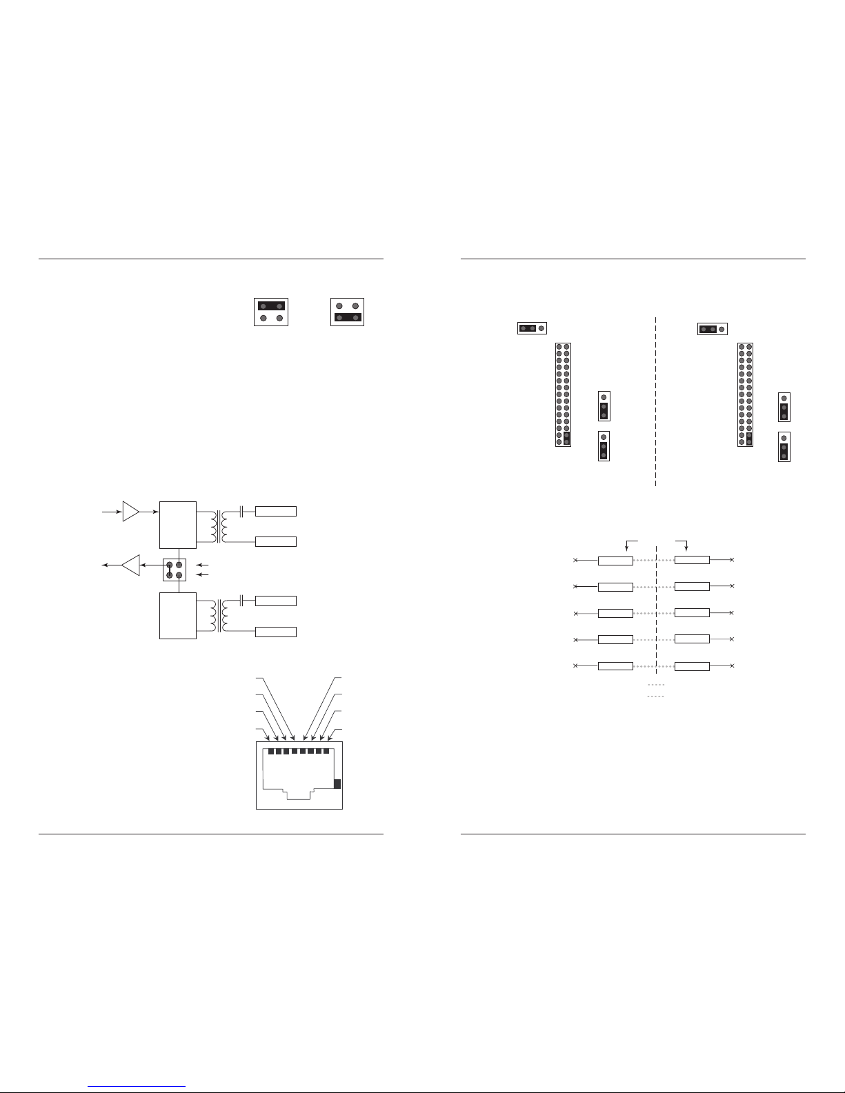
The figure below is a connection diagram for the 2-wire and 4-wire settings. For
the 2-wire interface, the send and receive paths for the audio signals are
transmitted over a single pair of wires: Tip (4) and Ring (5). For the 4-wire
interface, the send and receive paths for the audio signals are in separate paths.
The send path is via the Tip (4) and Ring (5) wires while the receive path is via the
Tip-1(1) and Ring-1 (2) wires.
Note: Even though an E&M circuit may be classified as “4-wire”, it is likely to have
six or eight physical wires, depending on the signaling type and audio
implementation that are used.
RJ-45 Connnector
An understanding of the RJ-45
connector pins will provide
insight into how the
communication signals are
transmitted between the
CEMTF10xx-10x Device and
the communication devices via
the copper cable. The drawing
to the right identifies the 8 pins
within the RJ-45 connector.
Ring-1 (2)
Ring (5)
Tip-1 (1)
Receive
Circuit
Tip (4)
Hybrid
Tx
Rx
Connect 3 and 4 for the 4-wire setting
Connect 1 and 2 for the 2-wire setting
1
3
2
J2
4
output (4W)
or
input / output (2W)
input only
Audio interface (2-wire / 4-wire)
There are two types of audio interfaces: 2wire and 4-wire; which describe the number
of wires used to transmit audio signals. The
figure to the right illustrates the jumper
configurations for the 2-wire and 4-wire
implemetations.
Note: The jumper for the 2-wire or 4-wire setting (J2) must be set for any of the
E&M Signal Types described on pages 5-10.
J2
1
3
2-Wire
2
4
J2
1
3
4-Wire
2
4
Pin4 (Tip)
Pin3 (E)
Pin2 (Ring-1)
Pin1 (Tip-1)
Pin5 (Ring)
Pin6 (SG)
Pin7 (M)
Pin8 (SB)
5
techsupport@transition.com -- Click the “Transition Now” link for a live Web chat.
No Signaling
A “No Signalling” configuration is used for a leased line operation. Set the jumpers on
the “Side A” Device and the “Side B” Device as follows:
E (3)
Chassis
SG (6)
M (7)
SB (8)
Chassis
E (3)
SG (6)
M (7)
SB (8)
RJ-45 Pins
Jumper settings for: "Side A" Media
Converter
"Side B" Media
Converter
Connection diagrams for: "Side A" device
or: "Side A" Media Converter
"Side B" Media Converter
"Side B" device
JP1
1
3
1
J1
596
29
17
30
26
22
18
14
10
1
J1
596
29
17
30
26
22
18
14
10
JP2
1
3
JP3
1
3
JP1
1
3
JP2
1
3
JP3
1
3
The figure below illustrates the wiring connections for the “Side A” and “Side B”
devices that have been configured for no signaling. Note that there is no E&M
signaling between the two devices.
Page 4

6
CEMTF10xx-10x
24-Hour Technical Support: 1-800-260-1312 -- International: 00-1-952-941-7600
E&M Signal Type I
E&M Signal Type I is the most common interface in North America. Set the
jumpers on the “Side A” and “Side B” Devices as follows:
-48V
E (3)
Chassis
SG (6)
M (7)
SB (8)
Chassis
E (3)
SG (6)
M (7)
SB (8)
Jumper settings for: "Side A" Media
Converter
"Side B" Media
Converter
Connection diagrams for: "Side A" device
or: "Side A" Media Converter
"Side B" Media Converter
"Side B" device
RJ-45 Pins
Relay
Relay
Current
Detector
Current
Detector
earth
earth
JP1
1
3
1
J1
596
29
17
30
26
22
18
14
10
1
J1
596
29
17
30
26
22
18
14
10
JP2
1
3
JP3
1
3
JP1
1
3
JP2
1
3
JP3
1
3
* optional
* optional
(23-24)(23-24)
The figure below illustrates the wiring connections for the “Side A” and “Side B”
devices that have been configured for E&M Signal Type I. The specifics of the wiring
connections are as follows:
• Type I uses two leads for supervisor signaling: E and M.
• During inactivity, E-lead is open and M-lead is connected to ground.
• The PBX circuit (Side A) indicates the off-hook condition by connecting the
M-lead to the battery.
• The CO device (Side B) indicates the off-hook condition by connecting the Elead to ground.
* An optional configuration with a jumper installed on pins 23 and 24 (J1) will
complete the connection labeled “23-24” in the wiring diagram. The specifics of
the wiring diagram are the same whether or not the optional jumper is installed.
JP1
1
3
1
J1
596
29
17
30
26
22
18
14
10
-48V
E (3)
Chassis
SG (6)
M (7)
SB (8)
Chassis
E (3)
SG (6)
M (7)
SB (8)
-48V
RJ-45 Pins
Relay
Relay
Current
Detector
Current
Detector
Jumper settings for: "Side A" Media
Converter
"Side B" Media
Converter
earth
earth
1
J1
596
29
17
30
26
22
18
14
10
JP2
1
3
JP3
1
3
JP1
1
3
JP2
1
3
JP3
1
3
Connection diagrams for: "Side A" device
or: "Side A" Media Converter
"Side B" Media Converter
"Side B" device
7
techsupport@transition.com -- Click the “Transition Now” link for a live Web chat.
E&M Signal Type II
With E&M Signal Type II configuration, two CO device (“Side B”) nodes can be
connected back-to-back. For Type II configuration, set the jumpers on the “Side A”
Device and the “Side B” Device as follows:
The figure below illustrates the wiring connections for the “Side A” and “Side B”
devices that have been configured for E&M Signal Type II. The specifics of the wiring
connections are as follows:
• Type II uses four leads for supervision signaling: E, M, SB, and SG.
• During inactivity, both the E-lead and the M-lead are open.
• The PBX circuit (Side A) indicates the off-hook condition by connecting the
M-lead to the signal battery (SB) lead, which is connected to the battery of
the CO device (Side B).
• The CO device (Side B) indicates the off-hook condition by connecting the Elead to the signal ground (SG) lead, which is connected to the PBX circuit
(Side A) ground.
Page 5

8
CEMTF10xx-10x
24-Hour Technical Support: 1-800-260-1312 -- International: 00-1-952-941-7600
JP1
1
3
1
J1
596
29
17
30
26
22
18
14
10
-48V
E (3)
Chassis
SG (6)
M (7)
SB (8)
Chassis
E (3)
SG (6)
M (7)
SB (8)
-48V
RJ-45 Pins
Relay
Relay
Current
Detector
Current
Detector
Jumper settings for: "Side A" Media
Converter
"Side B" Media
Converter
earth
earth
1
J1
596
29
17
30
26
22
18
14
10
JP2
1
3
JP3
1
3
JP1
1
3
JP2
1
3
JP3
1
3
Connection diagrams for: "Side A" device
or: "Side A" Media Converter
"Side B" Media Converter
"Side B" device
E&M Signal Type III
E&M Signal Type III is not commonly used in modern systems. For this
configuration, set the jumpers on the “Side A” Device and the “Side B” Device as
follows:
The figure below illustrates the wiring connections for the “Side A” and “Side B”
devices that have been configured for E&M Signal Type III. The specifics of the
wiring connections are as follows:
• Type III uses four leads for supervision signaling: E, M, SB, and SG.
• During inactivity, the E-lead is open and the and the M-lead is set to ground,
which is connected to the SG lead of the CO device (Side B).
• The PBX circuit (Side A) indicates the off-hook condition by connecting the
M-lead to the (SG) lead and connecting it to the SB lead of the CO device
(Side B).
• The CO device (Side B) indicates the off-hook condition by connecting the Elead to ground.
9
techsupport@transition.com -- Click the “Transition Now” link for a live Web chat.
JP1
1
3
1
J1
596
29
17
30
26
22
18
14
10
-48V
E (3)
Chassis
SG (6)
M (7)
SB (8)
Chassis
E (3)
SG (6)
M (7)
SB (8)
-48V
RJ-45 Pins
Relay
Relay
Current
Detector
Current
Detector
Jumper settings for: "Side A" Media
Converter
"Side B" Media
Converter
earth
earth
1
J1
596
29
17
30
26
22
18
14
10
JP2
1
3
JP3
1
3
JP1
1
3
JP2
1
3
JP3
1
3
Connection diagrams for: "Side A" device
or: "Side A" Media Converter
"Side B" Media Converter
"Side B" device
E&M Signal Type IV
As in Type III, E&M Signal Type IV is also not commonly used in modern systems.
For this configuration, set the jumpers on the “Side A” Device and the “Side B”
Device as follows:
The figure below illustrates the wiring connections for the “Side A” and “Side B”
devices that have been configured for E&M Signal Type IV. The specifics of the
wiring connections are as follows:
• Type IV uses four leads for supervision signaling: E, M, SB, and SG.
• During inactivity, the E-lead iand the M-lead are open.
• The PBX circuit (Side A) indicates the off-hook condition by connecting the
M-lead to the (SG) lead.
• The CO device (Side B) indicates the off-hook condition by connecting the Elead to the SG lead.
Page 6

10
CEMTF10xx-10x
24-Hour Technical Support: 1-800-260-1312 -- International: 00-1-952-941-7600
JP1
1
3
1
J1
596
29
17
30
26
22
18
14
10
-48V
E (3)
Chassis
SG (6)
M (7)
SB (8)
Chassis
E (3)
SG (6)
M (7)
SB (8)
-48V
RJ-45 Pins
Relay
Relay
Current
Detector
Current
Detector
Jumper settings for: "Side A" Media
Converter
"Side B" Media
Converter
earth
earth
(23-24)(23-24)
1
J1
596
29
17
30
26
22
18
14
10
JP2
1
3
JP3
1
3
JP1
1
3
JP2
1
3
JP3
1
3
Connection diagrams for: "Side A" device
or: "Side A" Media Converter
"Side B" Media Converter
"Side B" device
* optional
* optional
E&M Signal Type V
E&M Signal Type V is symmetrical and allows two CO devices (Side B) nodes to be
connected back-to-back. This signal type is also the most common interface type
used outside North America. For this configuration, set the jumpers on the “Side
A” and “Side B” Devices as follows:
The figure below illustrates the wiring connections for the “Side A” and “Side B”
devices that have been configured for E&M Signal Type IV. The specifics of the
wiring connections are as follows:
• Type V uses two leads for supervision signaling: E and M.
• During inactivity, the E-lead and the M-lead are open.
• The PBX circuit (Side A) indicates the off-hook condition by connecting the
M-lead to ground.
• The CO device (Side B) indicates the off-hook condition by connecting the Elead to ground.
* An optional configuration with a jumper installed on pins 23 and 24 (J1) will
complete the connection labeled “23-24” in the wiring diagram. The specifics of
the wiring diagram are the same whether or not the optional jumper is installed.
11
techsupport@transition.com -- Click the “Transition Now” link for a live Web chat.
Install the Slide-in-Module
To install the CEMTF10xx-10x Device slide-in-module:
1. Locate two adjacent, empty installation slots on the PointSystem™ chassis.
2. Carefully slide the slide-in-module into the installation slots, aligning the
module with the installation guides.
3. Ensure the module is seated inside the chassis.
4. Push in and rotate the attached panel fastener screw to secure the
module to the chassis front.
10BASE-T
INPORT
OUTPORT
DB-9
12C
12C-1TERM
INIT
LKS
PWR
LKM
LKS
PWR
LKM
Multimode
Singlemode
TX
RX
TX
RX
LKF
PWR
RXF
RXC
LKC
SPD
PWR
FRX
CRX
FLNK
CLNK
RX
TX
100BASE-TX
RX
TX
100BASE-FX
Link Alert
E
D
0
50½
Multimode
Singlemode
TX
RX
TX
RX
LA
PWR
RXF
RXC
LNK
COL
10BASE-2
10BASE-FL
LKS
PWR
LKM
LKS
PWR
LKM
Multimode
Singlemode
TX
RX
TX
RX
Multimode
Singlemode
TX
RX
TX
RX
10BASE-T
10BASE-FL
Media
Conversion
Center
Power
In Use
1
Power
In Use
2
RX
TX
LNK
PWR
RESET
DB-9
Panel Fastener Screw
Install the Fiber Cable
1. Locate or build fiber cable with male, two-stranded TX to RX connectors
installed at both ends.
2. Connect the fiber cable to the “Side A” Device as described:
• Connect the male TX cable connector to the female TX connector.
• Connect the male RX cable connector to the female RX connector.
“Side A” “Side B”
3. Connect the fiber cable to the “Side B” Device as described:
• Connect the male TX cable connector to the female RX connector.
• Connect the male RX cable connector to the female TX connector.
ACT SDF PWR
TX
RX
ACT SDF PWR
TX
RX
Fiber
Fiber
Page 7

13
techsupport@transition.com -- Click the “Transition Now” link for a live Web chat.
SNMP
See the on-line documentation that comes with Transition Networks FocalPoint™
software for applicable commands and usage.
Use SNMP at an attached terminal or at a remote location to monitor the Device
by monitoring:
• Device power
• Copper link status
• Fiber link status
• Copper receive status
• Fiber receive status
Also, use SNMP to enter network commands that:
• Power down the Device.
Operation
Power the Slide-in-Module
The slide-in-module is powered through the PointSystem™ chassis.
Status LEDs
Use the status LEDs to monitor the CEMTF10xx-10x Device operation in the
network.
PWR (Power) Steady LED indicates power is
on.
SDF (Signal Detect Fiber Link) Steady LED
indicates the fiber link is active.
ACT (Active Link) Steady LED indicates the
local unit is off the hook.
ACT SDF PWR
12
CEMTF10xx-10x
24-Hour Technical Support: 1-800-260-1312 -- International: 00-1-952-941-7600
Install the Copper Cable
1. Locate or build two custom copper cables with a male, RJ-45 connector at
one end and a connector of choice at the other end.
2. Connect the copper cable to the “Side A” Device as described:
• Connect the RJ-45 connector at
one end of the cable to the RJ45 port on the “Side A” Device.
• Connect the connector of
choice at the other end of the
cable to the port on the CO
device. (RJ-45 connector is shown
in the drawing.)
3. Connect the copper cable to the “Side B” Device as described:
• Connect the RJ-45 connector at one end of the cable to the RJ-45 port
on the on the “Side B” Device.
• Connect the connector of
choice at the other end of the
cable to the port on the PBX
device. (RJ-45 connector is shown
in the drawing.)
Connect the
connector of choi
ce
to the CO device.
Copper
Fiber
(RJ-45
shown)
FCC Part 68
Copper
Connect the
connector of choi
ce
to the PBX device
.
Fiber
(RJ-45 shown)
FCC Part 68
“Side A”
“Side B”
Page 8

14
CEMTF10xx-10x
24-Hour Technical Support: 1-800-260-1312 -- International: 00-1-952-941-7600
Cable Specifications
The physical characteristics must meet or exceed FCC Part 68 specifications.
Fiber Cable
Bit Error Rate: <10-9
Single mode fiber (recommended): 9 µm
Multimode fiber (recommended): 62.5/125 µm
Multimode fiber (optional): 100/140, 85/140, 50/125 µm
CEMTF1011-100 1300 nm multimode
Fiber Optic Transmitter Power: min: -19.0 dBm max: -14.0 dBm
Fiber Optic Receiver Sensitivity: min: -30.0 dBm max: -14.0 dBm
Link Budget: 11.0 dB
CEMTF1013-100 850 nm multimode
Fiber Optic Transmitter Power: min: -19.0 dBm max: -14.0 dBm
Fiber Optic Receiver Sensitivity: min: -30.0 dBm max: -14.0 dBm
Link Budget: 11.0 dB
CEMTF1014-100 1310 nm single mode
Fiber Optic Transmitter Power: min: -15.0 dBm max: -8.0 dBm
Fiber Optic Receiver Sensitivity: min: -31.0 dBm max: -8.0 dBm
Link Budget: 16.0 dB
CEMTF1015-100 1310 nm single mode
Fiber Optic Transmitter Power: min: -8.0 dBm max: -2.0 dBm
Fiber Optic Receiver Sensitivity: min: -34.0 dBm max: -7.0 dBm
Link Budget: 26.0 dB
CEMTF1029-100 1310(TX)/1550(RX) nm single mode
Fiber Optic Transmitter Power: min: -13.0 dBm max: -6.0 dBm
Fiber Optic Receiver Sensitivity: min: -32.0 dBm max: -3.0 dBm
Link Budget: 19.0 dB
CEMTF1029-101 1550(TX)/1310(RX) nm single mode
Fiber Optic Transmitter Power: min: -13.0 dBm max: -6.0 dBm
Fiber Optic Receiver Sensitivity: min: -32.0 dBm max: -3.0 dBm
Link Budget: 19.0 dB
CEMTF1029-102 1310(TX)/1550(RX) nm single mode
Fiber Optic Transmitter Power: min: -8.0 dBm max: -3.0 dBm
Fiber Optic Receiver Sensitivity: min: -33.0 dBm max: -3.0 dBm
Link Budget: 25.0 dB
CEMTF1029-103 1550(TX)/1310(RX) nm single mode
Fiber Optic Transmitter Power: min: -8.0 dBm max: -3.0 dBm
Fiber Optic Receiver Sensitivity: min: -33.0 dBm max: -3.0 dBm
Link Budget: 25.0 dB
The fiber optic transmitters on this device meet Class I Laser safety
requirements per IEC-825/CDRH standards and comply with 21 CFR1040.10
and 21CFR1040.11.
15
techsupport@transition.com -- Click the “Transition Now” link for a live Web chat.
Cable Specifications - Continued
Copper Cable
Shielded twisted pair (STP) or unshielded twised pair (UTP) is acceptable
Maximum # Nodes: 2
Maximum Cable Length: 5 km (3.1 miles)
Category 3 (minimum requirement)
Gauge: 24 to 22 AWG
Attenuation: 11.5 dB/100m @ 5-10 MHz
Category 5 (acceptable)
Gauge: 24 to 22 AWG
Attenuation: 22.0 dB/100m @ 5-10 MHz
Page 9

16
CEMTF10xx-10x
24-Hour Technical Support: 1-800-260-1312 -- International: 00-1-952-941-7600
Technical Specifications
For use with Transition Networks Model CEMTF10xx-10x or equivalent
Standards FCC Part 68
Data Rate 25 mhz (over fiber cable)
Dimensions 2.9" x 4.8" x 1.4" (74 mm x 122 mm x 36 mm)
Weight 8 oz (227 g) approximately
Power Consumption 9.0 watts
MTBF 522,000 hours (MIL217F2 V5.0) (MIL-HDBK-217F)
939,000 hours (Bellcore7 V5.0)
Environment Tmra*: 0 to 60°C (32° to 140° F )
Storage Temperature: -15° to 65°C (-4° to 122°F)
Humidity: 5-95%, non condensing
Altitude: 0-10,000 feet
Warranty Lifetime
*Manufacturer’s rated ambient temperature: Tmra range for this slide-in-module
depends on the physical characteristics and the installation configuration of the
Transition Networks PointSystem™ chassis in which this slide-in-module will be
installed.
The information in this user’s guide is subject to change. For the most up-to-date
information on the CEMTF10xx-10x Device, view the user’s guide on-line at:
www.transition.com.
Product is certified by the manufacturer to comply with DHHS Rule 21/CFR,
Subchapter J applicable at the date of manufacture.
CAUTION:
Visible and invisible laser radiation when open. Do not stare into the
beam or view directly with optical instruments.
CAUTION:
Use of controls, adjustments or the performance of procedures other
than those specified herein may result in hazardous radiation exposure.
17
techsupport@transition.com -- Click the “Transition Now” link for a live Web chat.
Troubleshooting
1. Is the PWR (power) LED illuminated?
NO
• Is the Device slide-in-module installed properly in the chassis?
• Is the power cord properly installed in the chassis and at the external
power source?
• Does the external power source provide power?
• Contact Technical Support: US/Canada: 1-800-260-1312, International: 001-952-941-7600.
YES
• Proceed to step 2.
2. Is the SDF (signal detect fiber link) LED illuminated?
NO
• Check fiber cables for proper connection.
• Verify that TX and RX cables on Device are connected to RX and TX
ports, respectively, on the other device.
• Contact Technical Support: US/Canada: 1-800-260-1312, International: 001-952-941-7600.
YES
• Proceed to step 3.
3. Is the ACT (active) LED illuminated?
NO
• Ensure that the local unit is off-hook.
• Contact Technical Support: US/Canada: 1-800-260-1312, International: 001-952-941-7600.
YES
• Contact Technical Support: US/Canada: 1-800-260-1312, International: 001-952-941-7600.
Page 10

18
CEMTF10xx-10x
24-Hour Technical Support: 1-800-260-1312 -- International: 00-1-952-941-7600
Compliance Information
CISPR22/EN55022 Class A + EN55024
CE Mark
FCC Regulations
This equipment has been tested and found to comply with the limits for a class A digital device,
pursuant to part 15 of the FCC rules. These limits are designed to provide reasonable protection
against harmful interference when the equipment is operated in a commercial environment. This
equipment generates, uses, and can radiate radio frequency energy and, if not installed and used in
accordance with the instruction manual, may cause harmful interference to radio communications.
Operation of this equipment in a residential area is likely to cause harmful interference, in which
case the user will be required to correct the interference at the user's own expense.
Canadian Regulations
This digital apparatus does not exceed the Class A limits for radio noise for digital apparatus set
out on the radio interference regulations of the Canadian Department of Communications.
Le présent appareil numérique n'émet pas de bruits radioélectriques dépassant les limites
applicables aux appareils numériques de la class A prescrites dans le Règlement sur le brouillage
radioélectrique édicté par le ministère des Communications du Canada.
European Regulations
Warning
This is a Class A product. In a domestic environment this product may cause radio interference in
which case the user may be required to take adequate measures.
Achtung !
Dieses ist ein Gerät der Funkstörgrenzwertklasse A. In Wohnbereichen können bei Betrieb dieses
Gerätes Rundfunkstörungen auftreten. In diesem Fäll ist der Benutzer für Gegenmaßnahmen
verantwortlich.
Attention !
Ceci est un produit de Classe A. Dans un environment domestique, ce produit risque de créer des
interférences radioélectriques, il appartiendra alors à l'utilsateur de prende les measures spécifiques
appropriées.
VCCI Class 1 Compliance
This equipment is in the 1st Class category (information equipment to be used in commercial
and/or industrial areas) and conforms to the standards set by the Voluntary Control Council For
Interference by Data Processing Equipment and Electronic Office Machines aimed at preventing
radio interference in commercial and/or industrial areas. When used in a residential area or in an
adjacent area thereto, interference may be caused to radio and TV receivers, etc. Read the
instructions for correct handling.
19
techsupport@transition.com -- Click the “Transition Now” link for a live Web chat.
Declaration of Conformity
Name of Mfg: Transition Networks
10900 Red Circle Drive, MinnetonkaMN 55343 U.S.A.
Model: CEMTF10xx-10x Series Devices
Part Number(s): CEMTF1011-100, CEMTF1012-100, CEMTF1013-100, CEMTF1014-100,
CEMTF1015-100, CEMTF1029-100, CEMTF1029-101, CEMTF1029-102,
CEMTF1029-103
Regulation: EMC Directive 89/336/EEC
Purpose: To declare that the CEMTF10xx-10x to which this declaration refers is in conformity
with the following standards.
TIA/EIA 464B, ANSI T1.409-1996, ANSI TR.5, FCC Part 68, EIA/TIA-464-B,
FCC Class A, VCCI Class A, EN 55022(CISPR 22) Class A, ICES-003
I, the undersigned, hereby declare that the equipment specified above conforms to the above Directive(s) and
Standard(s).
July 2008
Stephen Anderson, Vice-President of Engineering Date
Contact Us
Technical Support
Technical support is avialable 24 hours a day.
US and Canada: 1-800-260-1312
International: 00-1-952-941-7600
Transition Now
Chat live via the Web with Transition Networks Technical Support.
Log onto www.transition.com and click the Transition Now link.
Web-Based Seminars
TRANSITION Networks provides seminars via live web-based training.
Log onto www.transition.com and click the Learning Center link.
E-Mail
Ask a question anytime by sending an e-mail to our technical support staff.
techsupport@transition.com
Address
TRANSITION Networks
10900 Red Circle Drive
Minnetonka, MN 55343, U.S.A.
telephone: 952-941-7600
toll free: 800-526-9267
fax: 952-941-2322
Page 11

20
Trademark Notice
All registered trademarks and trademarks are the property of their respective owners.
Copyright Restrictions
© 2003, 2005 Transition Networks.
All rights reserved. No part of this work may be reproduced or used in any form or by any means
- graphic, electronic, or mechanical - without written permission from Transition Networks.
Printed in the U.S.A.
33252.D
 Loading...