

Transition Networks CDFTF1414-100, CDFTF1717-100, CDFTF1616-100, CDFTF2929-101, CDFTF2929-100 User Manual
...Page 1
Installation . . . . . . . . . . . . . . . . . .5
Operation . . . . . . . . . . . . . . . . . . .7
Technical Specifications . . . . . . . .8
Cable Specifications . . . . . . . . . . .9
Troubleshooting . . . . . . . . . . . . .10
Contact Us . . . . . . . . . . . . . . . . .11
Compliance Information . . . . . . .12
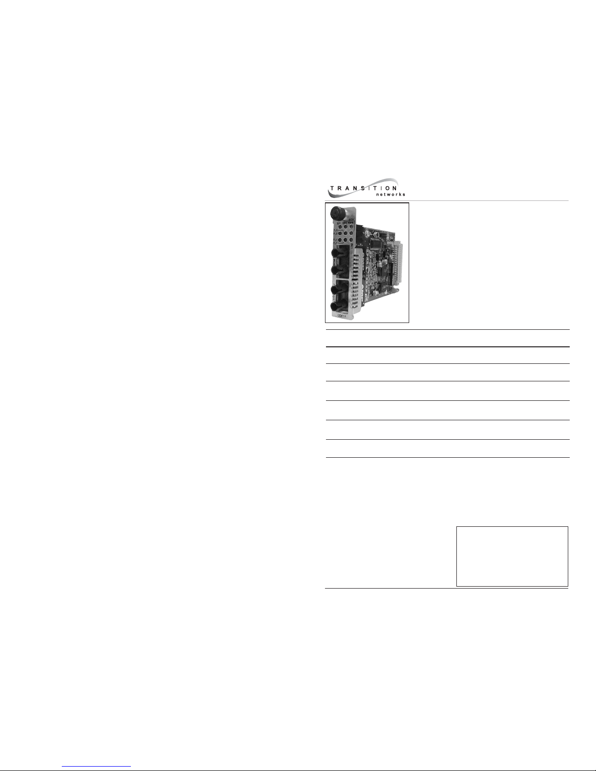
User’s Guide
CDFTFxxxx-10x
Slide-in-Module Media Converter
• Telco Network
• Copper to Fiber
• 100Base-TX to 100Base-FX
Transition Networks CDFTFxxxx-10x series dualport media converters are designed to be installed in
a CPSMC1850-150 PointSystem™ chassis. The
CDFTFxxxx-10x connects twisted-pair copper Telco
signals (received at the back of the CPSMC1850-150
chassis) to fiber-optic cable ports on each
CDFTFxxxx-10x series media converter (installed at
the front of the CPSMC1850-150 chassis).
Part Number Copper - Twisted-pair
Telco signals
Fiber-Optic - Two (2) external
100Base-FX ports
CDFTF1111-100 Two (2)
internal signals
ST, 1300 nm multimode
2 km (1.2 miles)*
CDFTF1313-100 Two (2)
internal signals
SC, 1300 nm multimode
2 km (1.2 miles)*
CDFTF1414-100 Two (2)
internal signals
SC, 1310 nm single mode
20 km (12.4 miles)*
CDFTF1717-100 Two (2)
internal signals
SC, 1550 nm single mode
80 km (49.7 miles)*
CDFTF1515-100 Two (2)
internal signals
SC, 1310 nm single mode
40 km (24.9 miles)*
CDFTF1616-100 Two (2)
internal signals
SC, 1310 nm single mode
60 km (37.3 miles)*
* Typical maximum cable distance. Actual distance is dependent upon the
physical characteristics of the network installation.
Page 2
CDFTFxxxx-10x
2
24-hour Technical Support: 1-800-260-1312 -- International: 00-1-952-941-7600
CDFTF2929-100 and CDFTF2929-101 are intended to be installed in the same
network where one is the local converter and the other is the remote converter.
CDFTF2929-102 and CDFTF2929-103 are intended to be installed in the same
network where one is the local converter and the other is the remote converter.
* Typical maximum cable distance. Actual distance is dependent upon the
physical characteristics of the network. (TX) = transmit, (RX) = receive
Part Number Copper - Twisted-pair
Telco signals
Fiber-Optic - Two (2) external
100Base-FX ports
CDFTF2929-100 Two (2)
internal signals
SC, 1310 mn (TX)/1550 nm (RX)
20 km (12.4 miles)*
CDFTF2929-101 Two (2)
internal signals
SC, 1550 mn (TX)/1310 nm (RX)
20 km (12.4 miles)*
CDFTF2929-102 Two (2)
internal signals
SC, 1310 mn (TX)/1550 nm (RX)
40 km (24.8 miles)*
CDFTF2929-103 Two (2)
internal signals
SC, 1550 mn (TX)/1310 nm (RX)
40 km (24.8 miles)*
Part Number Description
CPSMC1850-150 18-slot PointSystem™ chassis with two (2) external RJ-21
Telco connectors. **
21HC45-6 Telco cable with RJ-21 connector at one end and twelve (12)
RJ-45 connectors at the other end.
21HC21-6 Telco cable with RJ-21 connectors at both ends.
Related Transition Networks Equipment (sold separately)
**For more information on the CPSMC1850-150 chassis, see the user’s guide on-
line at www.transition.com
CPSMC1850-150 Chassis
The CPSMC1850-150 PointSystem™ chassis provides two (2) 50-pin Telco
connectors installed at the chassis back. The two Telco 50-pin connectors
concentrate a total of 24 UTP connections, which are distributed to twelve
(12) installation slots in the front of the CPSMC1850-150 chassis.
I
0
RJ-21 Telco connector #2
RJ-21 Telco connector #1
3
techsupport@transition.com -- Click the “Transition Now” link for a live Web chat.
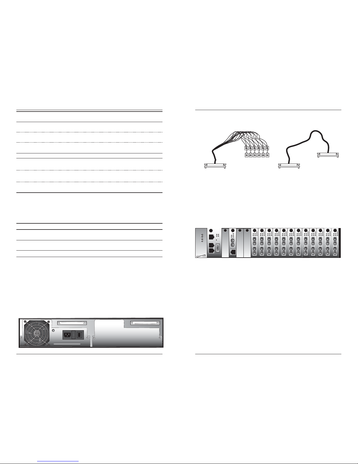
Telco Cables and Signals
The two kinds of Telco cables available from Transition Networks are pictured
below:
The signals from the Telco connectors are distributed as follows:
• Signals from Telco connector #2 go to chassis slots 7 - 12.
• Signals from Telco connector #1 go to chassis slots 13 - 18.
1
18
11
12
13
141516
17
10
2
3
9
8
4
5
7
6
{
{
Telco connector #2 Telco connector #1
10BASE-T
INPORT
MCCM10
MGMT MASTER
OUTPORT
DB-9
12C
12C-1TERM
INIT
CETTF100
LKF
PWR
RXF
RXC
LKC
RX
TX
10BASE-T
10BASE-FL
Media
Conversion
Center
Power
In Use
1
Power
In Use
2
RX
TX
LNK
PWR
RESET
DB-9
CDFTF100
Fiber Port #1
Fiber Port #2
CDFTF100
Fiber Port #1
Fiber Port #2
CDFTF100
Fiber Port #1
Fiber Port #2
CDFTF100
Fiber Port #1
Fiber Port #2
CDFTF100
Fiber Port #1
Fiber Port #2
CDFTF100
Fiber Port #1
Fiber Port #2
CDFTF100
Fiber Port #1
Fiber Port #2
CDFTF100
Fiber Port #1
Fiber Port #2
CDFTF100
Fiber Port #1
Fiber Port #2
CDFTF100
Fiber Port #1
Fiber Port #2
CDFTF100
Fiber Port #1
Fiber Port #2
CDFTF100
Fiber Port #1
Fiber Port #2
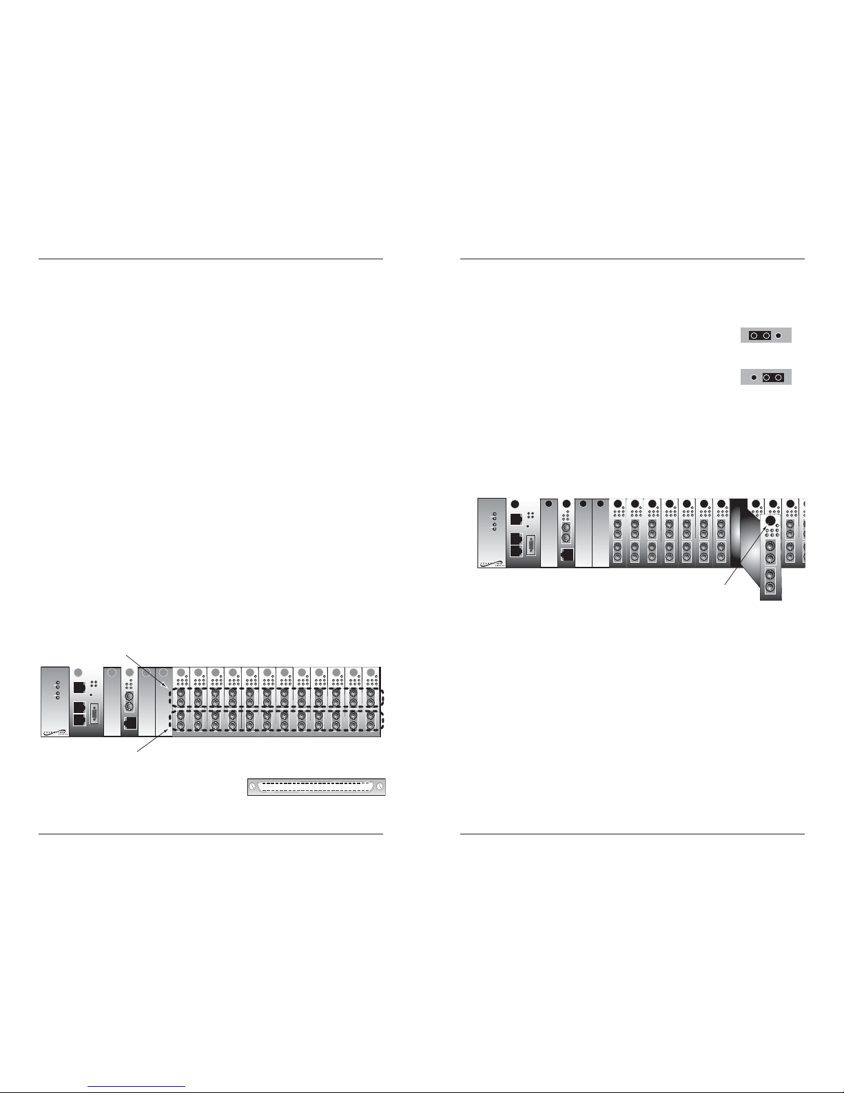
In order to fully utilize the Telco option on the CPSMC1850-150 chassis, the
Transition Networks CDFTFxxxx-10x is required and it must be installed in
slots 7 through 18.
Please note:
• Slots 1-6 on the CPSMC1850-150 are designed for any Transition
Networks media converter slide-in-module.
• Slots 7-18 on the CPSMC1850-150 can accommodate any Transition
Networks media converter slide-in-module. However the Telco option
will not function unless a CDFTFxxxx-10x media converter is installed in
those slots.
21HC45-6:
one (1) RJ-21 connector
and 12 RJ-45 connectors
21HC21-6:
two (2) RJ-21 connector
Page 3
CDFTFxxxx-10x
4
24-hour Technical Support: 1-800-260-1312 -- International: 00-1-952-941-7600
The chart also shows how the signals are distributed to either the UPPER or
LOWER port on the CDFTFxxxx-10x (see figure below).
25
1
50
26
The figure to the right illustrates the locations
of pins 1-50 on the Telco connector.
10BASE-T
INPORT
MCCM10
MGMT MASTER
OUTPORT
DB-9
12C
12C-1TERM
INIT
CETTF100
LKF
PWR
RXF
RXC
LKC
RX
TX
10BASE-T
10BASE-FL
Media
Conversion
Center
Power
In Use
1
Power
In Use
2
RX
TX
LNK
PWR
RESET
DB-9
CDFTF100
Fiber Port #1
Fiber Port #2
CDFTF100
Fiber Port #1
Fiber Port #2
CDFTF100
Fiber Port #1
Fiber Port #2
CDFTF100
Fiber Port #1
Fiber Port #2
CDFTF100
Fiber Port #1
Fiber Port #2
CDFTF100
Fiber Port #1
Fiber Port #2
CDFTF100
Fiber Port #1
Fiber Port #2
CDFTF100
Fiber Port #1
Fiber Port #2
CDFTF100
Fiber Port #1
Fiber Port #2
CDFTF100
Fiber Port #1
Fiber Port #2
CDFTF100
Fiber Port #1
Fiber Port #2
CDFTF100
Fiber Port #1
Fiber Port #2
lower ports
upper ports
Telco Connectors and Signals -- Continued
The chart below shows the 50 signals that go through each Telco connector on
the CPSMC1850-150 to slots 7-12 (Telco connector #2) OR to slots 13-18 (Telco
connector #1).
{
{
{
{
{
{
upper
{
lower
{
upper
{
lower
{
upper
{
lower
{
upper
{
lower
{
upper
{
lower
{
upper
{
lower
{
Pin # Signal Pin # Signal
1 Port 1 Transmit - 26 Port 1 Transmit +
2 Port 1 Receive - 27 Port 1 Receive +
3 Port 2 Transmit - 28 Port 2 Transmit +
4 Port 2 Receive - 29 Port 2 Receive +
5 Port 3 Transmit - 30 Port 3 Transmit +
6 Port 3 Receive - 31 Port 3 Receive +
7 Port 4 Transmit - 32 Port 4 Transmit +
8 Port 4 Receive - 33 Port 4 Receive +
9 Port 5 Transmit - 34 Port 5 Transmit +
10 Port 5 Receive - 35 Port 5 Receive +
11 Port 6 Transmit - 36 Port 6 Transmit +
12 Port 6 Receive - 37 Port 6 Receive +
13 Port 7 Transmit - 38 Port 7 Transmit +
14 Port 7 Receive - 39 Port 7 Receive +
15 Port 8 Transmit - 40 Port 8 Transmit +
16 Port 8 Receive - 41 Port 8 Receive +
17 Port 9 Transmit - 42 Port 9 Transmit +
18 Port 9 Receive - 43 Port 9 Receive +
19 Port 10 Transmit - 44 Port 10 Transmit +
20 Port 10 Receive - 45 Port 10 Receive +
21 Port 11 Transmit - 46 Port 11 Transmit +
22 Port 11 Receive - 47 Port 11 Receive +
23 Port 12 Transmit - 48 Port 12 Transmit +
24 Port 12 Receive - 49 Port 12 Receive +
25 N.C. 50 N.C.
Chassis Slot
#7 or 13
Chassis Slot
#8 or 14
Chassis Slot
#9 or 15
Chassis Slot
#10 or 16
Chassis Slot
#11 or 17
Chassis Slot
#12 or 18
5
techsupport@transition.com -- Click the “Transition Now” link for a live Web chat.
Install the Slide-in-Module
CAUTION: Wear a grounding device and observe electrostatic discharge
precautions when installing the CDFTFxxxx-10x. Failure to observe this
caution could result in damage to, and subsequent failure of, the media
converter.
To install the CDFTFxxxx-10x into the CPSMC1850-150 PointSystem™
chassis:
1. Locate an empty installation slot on the PointSystem™ chassis.
2. Carefully slide the slide-in-module into the installation slot, aligning the
module’s circuit board with the installation guides.
3. Ensure that the module is firmly seated inside the chassis.
4. Push in and rotate the the attached panel fastener screw clockwise to
secure the module to the chassis front.
CAUTION: Slots in the PointSystem™ chassis without a slide-in-module
installed MUST have a protective plate covering the empty slot for Class A
compliance.
10BASE-T
INPORT
MCCM10
MGMT MASTER
OUTPORT
DB-9
12C
12C-1TERM
INIT
CETTF100
LKF
PWR
RXF
RXC
LKC
RX
TX
10BASE-T
10BASE-FL
Media
Conversion
Center
Power
In Use
1
Power
In Use
2
RX
TX
LNK
PWR
RESET
DB-9
CDFTF100
Fiber Port #1
Fiber Port #2
CDFTF100
Fiber Port #1
Fiber Port #2
CDFTF100
Fiber Port #1
Fiber Port #2
CDFTF100
Fiber Port #1
Fiber Port #2
CDFTF100
Fiber Port #1
Fiber Port #2
CDFTF100
Fiber Port #1
Fiber Port #2
CDFTF100
Fiber Port #1
Fiber Port #2
CDFTF100
Fiber Port #1
Fiber Port #2
CDFTF100
Fiber Port #1
Fiber Port #2
CDFTF100
Fiber Port #1
Fiber Port #2
C
D
Fiber Port #1
Fiber Port #2
CDFTF100
Fiber Port #1
Fiber Port #2
CDFTF100
Fiber Port #1
Fiber Port #2
panel fastener screw
Installation
Set the Hardware/Software Jumper
• The jumper is located on the circuit board and is labeled “H” and “S”.
• Use small needle-nose pliers to set the jumper.
Hardware The media converter settings such as
AutoCross and Link Pass-Through cannot be
changed.
Software The media converter settings are determined
by the most-recently saved, on-board
microprocessor settings.
Software Mode
Hardware Mode
H
S
H
S
Page 4

CDFTFxxxx-10x
6
24-hour Technical Support: 1-800-260-1312 -- International: 00-1-952-941-7600
Installation -- Continued
NOTE: The media converter does not support Auto-Negotiation. Set the
external devices to forced 100 Mb/s full-duplex.
Connect the Telco Copper Cable
CAUTION: The twisted-pair copper Telco cables must be less than 60 m (196
ft.). Failure to observe this caution could cause data transfer to fail.
1. Locate the 100Base-TX cable with the male 50-pin Telco connector at
one end and with twelve (12) RJ-45 connectors at other end (P/N
21HC45-6). Alternatively, the male 50-pin Telco connector at both ends
(P/N 21HC21-6) may also be used.
2. Connect the male 50-pin Telco cable connector to the female 50-pin
Telco connector at the chassis back.
3. Connect the twelve (12) RJ-45 connectors or the male 50-pin Telco cable
connector at the other cable end to the 100Base-TX Telco device(s).
4. Repeat steps 3 and 4 to connect the second 100Base-TX Telco cable to
the second 50-pin Telco connector at the chassis back.
Connect the Fiber Cable
1. Locate or build IEEE 803.2™ compliant 100Base-FX fiber cable with
male, two-stranded TX to RX connectors installed at both ends.
2. Connect the fiber cables to the CDFTFxxxx-10x media converter as
described:
• Connect the male TX cable connector to the female TX port.
• Connect the male RX cable connector to the female RX port.
3. Connect the fiber cables to the other device (another media converter,
hub, etc.) as described:
• Connect the male TX cable connector to the female RX port.
• Connect the male RX cable connector to the female TX port.
Power the Media Converter
The slide-in-module media converter is powered through the Transition
Networks PointSystem™ chassis.
Connect the fiber cable
to the media converter
as shown.
Connect the fiber cable
to the other device
(media converter,
hub, etc.) as shown
RX
TX
RX
TX
7
techsupport@transition.com -- Click the “Transition Now” link for a live Web chat.
Product Features
AutoCross™
When the AutoCross feature is activated, it allows either straight-through
(MDI) or crossover (MDI-X) copper cables to be used when connecting to
100Base-TX devices. AutoCross determines the characteristics of the
connection and automatically configures the unit to link up, regardless if the
copper cable is MDI or MDI-X configuration.
Link Pass Through
The Link Pass-Through feature allows the media converter to monitor both the
fiber and copper RX (receive) ports for loss of signal. In the event of a loss of
an RX signal (1), the media converter will automatically disable the TX
(transmit) signal (2), thus, “passing through” the link loss (3). The far-end
device is automatically notified of the link loss (4), which prevents the loss of
valuable data unknowingly transmitted over an invalid link.
4
1
Media
Converter A
Media
Converter B
Near-End
Device
Far-End
Device
original fault
on the copper link
media converter B
disables the copper lin
k
media converter A
disables the fiber TX link
3
2
media converter B
loses the fiber RX link
Operation
Status LEDs
Use the status LEDs to monitor the media converter
operation in the network
PWR Pow
er: On = Connection to external AC power.
TL1 Twisted-Pair Link 1: On = A link on the twisted-
pair Telco connection to media converter #1.
FL1 Fiber Link 1: On = A link on the fiber
connection to media converter #1.
AC1 Activity 1: Flashing = Activity on media
converter #1.
TL2 Twisted-Pair Link 2: On = A link on the
twisted-pair Telco connection to media
converter #2.
FL2 Fiber Link 2: On = A link on the fiber
connection to media converter #2.
AC2 Activity 2: Flashing = Activity on media
converter #2.
CDFTF100
Fiber Port #1
Fiber Port #2
PWR
AC1
TL1
FL1
AC2
TL2
FL2
Page 5

CDFTFxxxx-10x
8
24-hour Technical Support: 1-800-260-1312 -- International: 00-1-952-941-7600
Technical Specifications
For use with Transition Networks Model CDFTFxxxx-10x or equivalent.
Standards IEEE 802.3™
Data Rate 10 Mb/s
Dimensions 3.4" x 0.86" x 5.0" (86 x 22 x 127 mm)
Weight 3 oz (91 g) (approximate)
Power Consumption 6.8 watts
MTBF 484,000 hours (MIL217F2 V5.0) (MIL-HDBK-217F)
1,359,000 hours (Bellcore7 V5.0)
Environment Tmra*: 0 to 60°C (32 to 140°F )
Storage Temp: -20 to 85°C (-4 to 185°F)
Humidity: 5 to 95%, non condensing
Altitude: 0 to 10,000 feet
Warranty Lifetime
*Manufacturer’s rated ambient temperature: Tmra range for this slide-in-module
depends on the physical characteristics and the installation configuration of the
Transition Networks PointSystem™ chassis in which this slide-in-module will be
installed.
Product is certified by the manufacturer to comply with DHHS Rule 21/CFR,
Subchapter J applicable at the date of manufacture.
CAUTION: Visible and invisible laser radiation when open. Do not stare into
the beam or view directly with optical instruments.
CAUTION: Use of controls, adjustments or the performance of procedures other
than those specified herein may result in hazardous radiation exposure.
Operation -- Continued
SNMP
Use SNMP at an attached terminal or at a remote location to monitor the
media converter by monitoring:
• Media converter power.
• Copper link status on media converter #1.
• Fiber link status on media converter #1.
• Activity on media converter #1.
• Copper link status on media converter #1.
• Fiber link status on media converter #1.
• Activity on media converter #1.
Also, use SNMP to enter network commands that:
• Enable/disable AutoCross.
See the on-line documentation that comes with Transition Networks
FocalPoint™ software for commands and usage at www.transition.com.
9
techsupport@transition.com -- Click the “Transition Now” link for a live Web chat.
Cable Specifications
The physical characteristics must meet or exceed IEEE 802.3™ specifications.
Telco Copper Cable Maximum cable distance = 60 m (197 ft.)
Category 5: (minimum requirement)
Gauge 24 to 22 AWG
Attenuation 22.0 dB /100m @ 100 MHz
(See page 4 for the Telco cable signal distribution over the 50-pin
connector at the back of the CPSMC1850-150 PointSystem™ chassis.)
Fiber Cable
Bit Error Rate: <10-9
Single mode fiber (recommended): 9 µm
Multimode fiber (recommended): 62.5/125 µm
Multimode fiber (optional): 100/140, 85/140, 50/125 µm
CDFTF1111-100 1300 nm multimode
CDFTF1313-100 1300 nm multimode
Fiber Optic Transmitter Power: min: -19.0 dBm max: -14.0 dBm
Fiber Optic Receiver Sensitivity: min: -30.0 dBm max: -14.0 dBm
Link Budget: 11.0 dB
CDFTF1414-100 1310 nm single mode
Fiber-optic Transmitter Power: min: -15.0 dBm max: -8.0 dBm
Fiber-optic Receiver Sensitivity: min: -31.0 dBm max: -8.0 dBm
Link Budget: 16.0 dB
CDFTF1515-100 1310 nm single mode
Fiber-optic Transmitter Power: min: -8.0 dBm max: -2.0 dBm
Fiber-optic Receiver Sensitivity: min: -34.0 dBm max: -7.0 dBm
Link Budget: 26.0 dB
CDFTF1616-100 1310 nm single mode
CDFTF1717-100 1550 nm single mode
Fiber-optic Transmitter Power: min: -5.0 dBm max: 0.0 dBm
Fiber-optic Receiver Sensitivity: min: -34.0 dBm max: -7.0 dBm
Link Budget: 29.0 dB
CDFTF2929-100 1310 nm (TX)/1550 nm (RX) simplex
CDFTF2929-101 1550 nm (TX)/1310 nm (RX) simplex
Fiber-optic Transmitter Power: min: -13.0 dBm max: -6.0 dBm
Fiber-optic Receiver Sensitivity: min: -32.0 dBm max: -3.0 dBm
Link Budget: 19.0 dB
CDFTF2929-102 1310 nm (TX)/1550 nm (RX) simplex
CDFTF2929-103 1550 nm (TX)/1310 nm (RX) simplex
Fiber-optic Transmitter Power: min: -8.0 dBm max: -3.0 dBm
Fiber-optic Receiver Sensitivity: min: -33.0 dBm max: -3.0 dBm
Link Budget: 25.0 dB
The fiber optic transmitters on this device meets Class I Laser safety
requirements per IEC-825/CDRH standards and complies with 21
CFR1040.10 and 21CFR1040.11.
Page 6

CDFTFxxxx-10x
10
24-hour Technical Support: 1-800-260-1312 -- International: 00-1-952-941-7600
Troubleshooting
If the media converter fails, isolate and correct the fault by determining the
answers to the following questions and then taking the indicated action:
1. Is the Power LED on the media converter illuminated?
NO
• Is the media converter inserted properly into the chassis?
• Is the power cord properly installed in the chassis and at the external
power source?
• Does the external power source provide power?
• Contact Tech Support: 1-800-260-1312, Int’l: 00-1-952-941-7600.
YES
• Proceed to step 2.
2. Is the Twisted-Pair Link 1 LED illuminated?
NO
• Check the twisted-pair Telco cables for proper connection.
• Ensure that the twisted-pair copper Telco cable distance does not
exceed 60 meters.
• Contact Tech Support: 1-800-260-1312, Int’l: 00-1-952-941-7600.
YES
• Proceed to step 3.
3. Is the Fiber Link 1 LED illuminated?
NO
• Check the fiber cables for proper connection.
• Verify that the TX and RX cables on media converter are connected
to RX and TX ports, respectively, on the other device.
• Contact Tech Support: 1-800-260-1312, Int’l: 00-1-952-941-7600.
YES
• Proceed to step 4.
4. Is the Activity 1 LED illuminated?
NO
• Verify that data is being sent from the external devices.
• Verify that all external devices are set to forced 100 Mb/s full-duplex
for full-duplex operation.
• Contact Tech Support: 1-800-260-1312, Int’l: 00-1-952-941-7600.
YES
• Proceed to step 5.
5. Is the Twisted-Pair Link 2 LED illuminated?
NO
• Check twisted-pair Telco cables for proper connection.
• Ensure that the twisted-pair copper Telco cable distance does not
exceed 60 meters.
• Contact Tech Support: 1-800-260-1312, Int’l: 00-1-952-941-7600.
YES
• Proceed to step 6.
11
techsupport@transition.com -- Click the “Transition Now” link for a live Web chat.
Contact Us
Technical support is available 24 hours a day:
US / Canada: 1-800-260-1312, International: 00-1-952-941-7600
Chat live via the Web with Transition Networks Technical Support.
Log onto www.transition.com and click the Transition Now link.
Ask a question anytime by sending an e-mail to our technical support staff.
techsupport@transition.com
Transition Networks, 6475 City West Parkway, Minneapolis, MN 55344, USA
telephone: 952-941-7600, toll free: 800-526-9267, fax: 952-941-2322
Declaration of Conformity
Name of Mfg: Transition Networks
6475 City West Parkway, Minneapolis MN 55344 USA
Model: CDFTFxxxx-10x Series Media Converters
Part Number(s): CDFTF1111-100, CDFTF1313-100, CDFTF1414-100, CDFTF1515-100,
CDFTF1616-100, CDFTF1717-100, CDFTF2929-100, CDFTF2929-101,
CDFTF2929-102, CDFTF2929-103
Regulation: EMC Directive 89/336/EEC
Purpose: To declare that the
CDFTFxxxx-10x
to which this declaration refers is in
conformity with the following standards.
CISPR 22:1997+A1:2000; EN 55022:1998+A1:2000 Class A; EN 55024:1998;
FCC Part 15 Subpart B; EN 61000-3-2:1995+A14:2000; EN61000-3-3:1995
I, the undersigned, hereby declare that the equipment specified above conforms to the above
Directive(s) and Standard(s).
May 1, 2002
Stephen Anderson, Vice-President of Engineering Date
Troubleshooting -- Continued
6. Is the Fiber Link 2 LED illuminated?
NO
• Check the fiber cables for proper connection.
• Verify that the TX and RX cables on the media converter are
connected to the RX and TX ports, respectively, on the other device.
• Contact Tech Support: 1-800-260-1312, Int’l: 00-1-952-941-7600.
YES
• Proceed to step 7.
7. Is the Activity 2 LED illuminated?
NO
• Verify that data is being sent from the external devices.
• Verify that all external devices are set to forced 100 Mb/s full-duplex
for full-duplex operation.
• Contact Tech Support: 1-800-260-1312, Int’l: 00-1-952-941-7600.
YES
• Contact Tech Support: 1-800-260-1312, Int’l: 00-1-952-941-7600.
Page 7

Trademark Notice
All trademarks and registered trademarks are the property of their respective owners.
Copyright Restrictions
© 2002 - 2005 Transition Networks.
All rights reserved. No part of this work may be reproduced or used in any form or by any
means - graphic, electronic, or mechanical - without written permission from Transition
Networks.
Printed in the U.S.A.
33217.D
Compliance Information
CISPR22/EN55022 Class A + EN55204
CE Mark
FCC Regulations
This equipment has been tested and found to comply with the limits for a Class A digital
device, pursuant to part 15 of the FCC rules. These limits are designed to provide reasonable
protection against harmful interference when the equipment is operated in a commercial
environment. This equipment generates, uses, and can radiate radio frequency energy and, if
not installed and used in accordance with the instruction manual, may cause harmful
interference to radio communications. Operation of this equipment in a residential area is
likely to cause harmful interference, in which case the user will be required to correct the
interference at the user's own expense.
Canadian Regulations
This digital apparatus does not exceed the Class A limits for radio noise for digital apparatus
set out on the radio interference regulations of the Canadian Department of Communications.
Le présent appareil numérique n'émet pas de bruits radioélectriques dépassant les limites
applicables aux appareils numériques de la Class A prescrites dans le Règlement sur le
brouillage radioélectrique édicté par le ministère des Communications du Canada.
European Regulations
Warning This is a Class A product. In a domestic environment this product may cause radio
interference in which case the user may be required to take adequate measures.
Achtung! Dieses ist ein Gerät der Funkstörgrenzwertklasse A. In Wohnbereichen können
bei Betrieb dieses Gerätes Rundfunkstörungen auftreten. In diesem Fäll ist der Benutzer für
Gegenmaßnahmen verantwortlich.
Attention! Ceci est un produit de Classe A. Dans un environment domestique, ce produit
risque de créer des interférences radioélectriques, il appartiendra alors à l'utilsateur de
prende les measures spécifiques appropriées.
CAUTION: RJ connectors are NOT INTENDED FOR CONNECTION TO THE
PUBLIC TELEPHONE NETWORK. Failure to observe this caution could result in
damage to the public telephone network.
Der Anschluss dieses Gerätes an ein öffentlickes Telekommunikationsnetz in den EGMitgliedstaaten verstösst gegen die jeweligen einzelstaatlichen Gesetze zur Anwendung der
Richtlinie 91/263/EWG zur Angleichung der Rechtsvorschriften der Mitgliedstaaten über
Telekommunikationsendeinrichtungen einschliesslich der gegenseitigen Anerkennung ihrer
Konformität.
 Loading...