

Transition Networks CCSCF3011-110, CCSCF3013-110, CCSCF3014-110, CCSCF3015-110, CCSCF3016-110 User Manual
...Page 1
*Typical maximum cable distance. Actual distance is dependent upon the physical
characteristics of the network.
Part Number Port Two - Duplex Fiber-Optic
CCSCF3011-110
75 ohm coax (BNC) ST, 1300 nm multimode,
2 km (1.2 miles)*
CCSCF3013-110
75 ohm coax (BNC) SC, 1300 nm multimode,
2 km (1.2 miles)*
CCSCF3014-110
75 ohm coax (BNC) SC, 1310 nm single mode,
20 km (12.4 miles)*
CCSCF3015-110
75 ohm coax (BNC) SC, 1310 nm single mode,
40 km (24.8 miles)*
CCSCF3016-110
75 ohm coax (BNC) SC, 1310 nm single mode,
60 km (37.3 miles)*
CCSCF3017-110
75 ohm coax (BNC) SC, 1550 nm single mode,
80 km (49.7 miles)*
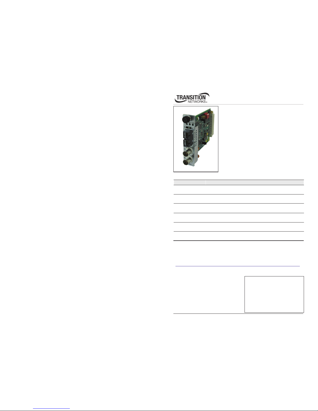
User’s Guide
CCSCF30xx-11x
Slide-In Card (SIC)
• DS3, ES/T3, and STS-1
• Coax (BNC) to Fiber
Transition Networks CCSCF30xx-11x series SICs
encode and decode DS3, E3/T3, or STS-1 coax copper
signals over fiber optic cable to extend the distance and
transmission reliability of high-speed DS3, E3/T3, or
STS-1 data traffic. The CCSCF30xx-11x is designed to
install in a Transition Networks PointSystem chassis.
Note: The SCSCF30xx-11x model is the standalone version. For more information, see
the SCSCF30xx-11x user’s guide on-line @:
http://www.transition.com/TransitionNetworks/Products2/ProductFinder/Default.aspx
Installation . . . . . . . . . . . . . . . . . . . . .2
Operation . . . . . . . . . . . . . . . . . . . . . .7
Cable Specifications . . . . . . . . . . . . . .8
Technical Specifications . . . . . . . . . .10
Troubleshooting . . . . . . . . . . . . . . . .11
Contact Us . . . . . . . . . . . . . . . . . . . .14
Compliance Information . . . . . . . . .15
Port One - Copper
Page 2
Part Number Port One - Copper Port Two - Single Fiber Optic
2
CCSCF30xx-11x
24-hour Technical Support: 1-800-260-1312 -- International: 00-1-952-941-7600
*Typical maximum cable distance; actual distance is dependent on the physical
characteristics of the network. (TX) = transmit (RX) = receive.
CCSCF3029-111**
75 ohm coax (BNC) SC, 1550 nm (TX)/1310 nm (RX)
single mode, 20 km (12.4 miles)*
CCSCF3029-112**
75 ohm coax (BNC) SC, 1310 nm (TX)/1550 nm (RX)
single mode, 40 km (24.8 miles)*
CCSCF3029-113**
75 ohm coax (BNC) SC, 1550 nm (TX)/1310 nm (RX)
single mode, 40 km (24.8 miles)*
CCSCF3029-115**
75 ohm coax (BNC) SC, 1550 nm (TX)/1310 nm (RX)
single mode, 60km (37.3.miles)*
CCSCF3029-114**
75 ohm coax (BNC) SC, 1310 nm (TX)/1550 nm (RX
single mode, 60km (37.3.miles)*
CCSCF3029-116**
75 ohm coax (BNC) SC, 1310 nm (TX)/1550 nm (RX
single mode, 80km (49.7.miles)*
CCSCF3029-117**
75 ohm coax (BNC) SC, 1550 nm (TX)/1310 nm (RX)
single mode, 80km (49.7.miles)*
CCSCF3040-110
75 ohm coax (BNC) SFP empty slot
CCSCF3029-110**
75 ohm coax (BNC) SC, 1310 nm (TX)/1550 nm (RX)
single mode, 20 km (12.4 miles)*
**CCSCF3029-110/-111, -112/-113, -114/-115, -116/-117 are intended to be installed, as a
grouped pair, in the same network with one being the local Device and the other being the
remote Device.
Installation
CAUTION: Wear a grounding device and observe electrostatic discharge precautions
when handling SICs. Failure to observe this caution could result in damage to the SIC.
Selecting hardware or software mode
The hardware/software header J11 is located on the circuit board. Use a small needlenose pliers or similar tool to move the jumper to the desired mode.
Hardware The mode of the SIC is determined by this
switch settings.
Software The mode of the SIC is determined by the
most-recently saved, on-board
microprocessor settings in this position.
J11
HS
J11
HS
Hardware
Softwa re
techsupport@transition.com -- Click the “Transition Now” link for a live Web chat.
3
Installation — Continued
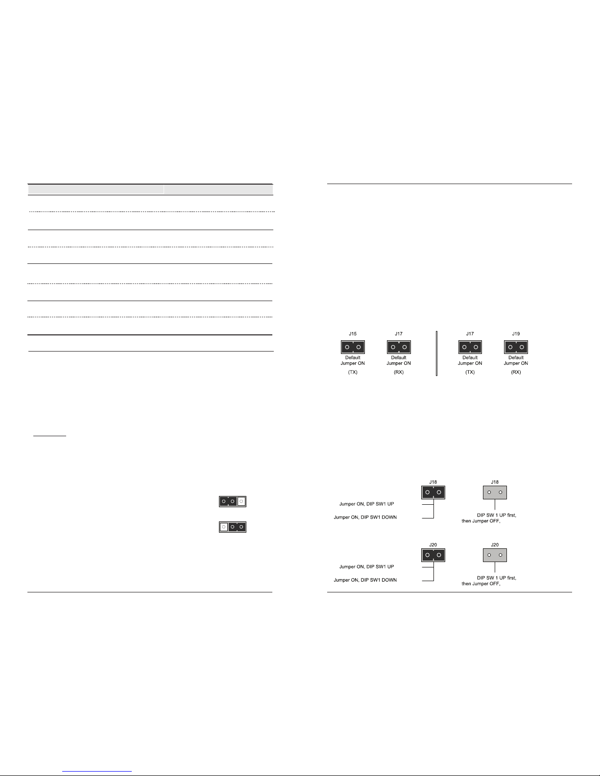
Set the coax grounding jumper (optional)
Note: Remove the jumpers on headers J15/J17, and J17/J19, only if necessary.
Headers J15/J17 Fixed Optic models, and J17/J19 SFP Models (located on the circuit
board near the coax ports) provide a grounding feature so that the CCSCF30xx-11x SIC
complies with ITU-T G.703 standard where:
• The TX output coax port outer shield is connected to earth ground.
• The RX input coax port outer shield is connected to earth ground.
The factory default settings for these two headers are:
Header (TX) (jumper ON) = Output coax port outer shield is connected to earth ground.
See J15 illustration below for fixed optic models and J17 for SFP Models.
Header (RX) (jumper ON) = Input coax port outer shield is connected to earth ground.
See J17 illustration below for fixed optic models and J19 for SFP Models
Fixed Optic Models
SFP Models
Data modes for Fixed Optic and SFP models
The CCSCF30xx-11x series SICs encode and decode DS3, E3/T3, or STS-1 coax
copper signals over fiber optic cable at the following data rates:
• DS3 (Digital signal) 44.7 Mbps
• E3 (European standard) 34.4 Mbps
• STS-1 (Synchronous transport signal) 51.8 Mbps
Factory default is DS3 mode (jumper on header J18 for the Fixed Optic models, and
J20 for the SFP Models with DIP SW1 UP). To select a different data mode, see
illustrations below.
(STS-1 Mode)
(DS3 Mode)
(E3 Mode)
(STS-1 Mode)
(DS3 Mode)
(E3 Mode)
Fixed Optic Models
SFP Models
Page 3
4
CCSCF30xx-11x
24-hour Technical Support: 1-800-260-1312 -- International: 00-1-952-941-7600
Switch 2 – Coax Line Build Out (DS3 only)
up - The DS3 line is setup to operate at distances up to 225 ft.
(68.6 m).
down - The DS3 line is setup to operate at distances greater than
225 ft. (68.6 m).
<225 ft (68.6 m)
>225 ft (68.6 m)
down
up
Installation — Continued
CAUTION: Wear a grounding device and observe electrostatic discharge precautions
when setting the configuration switches. Failure to observe this caution could result in
damage to the slide-in card.
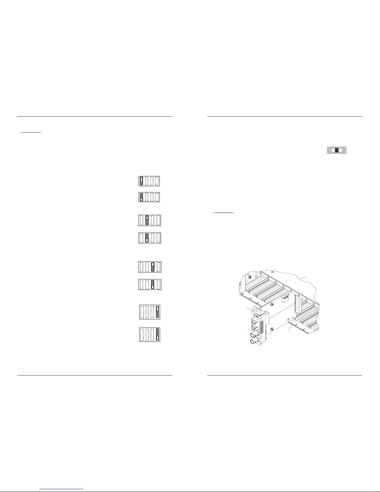
Setting up the configuration switches
The configuration switches are located on the circuit board. Use a small, flat-blade
screwdriver to set the recessed switches.
Switch 1 – Select DS3 or E3
up - Supports a DS3 interface.
down - Supports a E3 interface.
DS3
E3
down
up
Switch 3 – Signal on Loss of Carrier
up - Transmits an Alarm Indication Signal (AIS) on the loss of
the input carrier (unframed).
down - No signal is transmitted on the loss of the input carrier
(unframed).
Transmit alarm
No si
g
nal
up
down
Switch 4 – AIS Alarm
up - AIS alarm is defined as a pattern of alternating (1s and 0s)
unframed.
down - AIS alarm is defined as a pattern of all (1s) unframed.
Alarms = 1s and 0s
Alarm = all 1s
up
down
techsupport@transition.com -- Click the “Transition Now” link for a live Web chat.
5
Install the CCSCF30xx-11x SIC
CAUTION: Wear a grounding device and observe electrostatic discharge precautions
when installing the SIC. Failure to observe this caution could result in damage to the
SIC.
To install the SIC into the Transition Networks PointSystem chassis:
1. Locate an empty slot on the chassis.
2. Carefully slide the SIC into the chassis slot, aligning it with the installation guides.
3. Ensure that the SIC is firmly seated to the backplane of the chassis.
4. Push in and rotate the panel-fastener screw clockwise to secure the card to the
chassis frame.
Point System Chassis
Slide-In Card
Panel F astener
Slot
Installation — Continued
Set the loop-back switch
The loop-back switch is located on the front panel of the SIC. The switch is used in the
installation and network debugging procedures.
To set the switch, use a small flat-blade screwdriver or a
similar device (see the drawing).
CL (Coax loop-back) Enable loop-back on the local coax interface.
-- (Center Position) Normal operation.
FL (Fiber loop-back) Enable loop-back on the local fiber interface.
Note: Three loop-back test scenarios are described in detail in this manual.
CL F L
Page 4

CCSCF30xx-11x
6
24-hour Technical Support: 1-800-260-1312 -- International: 00-1-952-941-7600
Installation — Continued
Install the coax cable
1. Locate a coax cable with female connectors installed at both ends.
2. Connect the coax cables to the SIC as described:
• Connect the female TX cable connector to the male TX port.
• Connect the female RX cable connector to the male RX port.
3. Connect the coax cables to the other device (switch, workstation, etc.) as described:
• Connect the female TX cable connector to the male RX port.
• Connect the female RX cable connector to the male TX port.
Install the fiber cable
1. Locate a fiber cable with male, two-stranded TX to RX connectors installed at both
ends.
2. Connect the fiber cables to the local SIC as described:
• Connect the male TX cable connector to the female TX port.
• Connect the male RX cable connector to the female RX port.
3. Connect the fiber cables to the remote SIC as described:
• Connect the male TX cable connector to the female RX port.
• Connect the male RX cable connector to the female TX port.
Connect fiber cable
to media converter
as shown.
Connect fiber cable
to other device
(media converter,
hub, etc.) as shown
RX
TX
RX
TX
RX
TX
RX
TX
Connect the
coax cable to the
Medi a Converter
as shown
Connect the
coax c able to the
other devi ce as
shown
techsupport@transition.com -- Click the “Transition Now” link for a live Web chat.
7
Operation
After installation, the SIC should function without operator intervention.
Use the status LEDs to monitor SIC operation in the network.
SDC Green ON The coax link is up.
Green FLASHING The coax link is in loop-back
mode.
Yellow ON AIS on the coax link.
SDF Green ON The fiber link is up.
Green FLASHING The fiber link is in loop-back
mode.
Yellow ON AIS on the fiber link.
PWR Green ON The SIC is connected to power via
the chassis backplane.
SNMP
See the on-line documentation for Transition Networks’ FocalPoint™ software for
applicable commands and usage:
http://www.transition.com/TransitionNetworks/Products2/Static/focalpoint2.aspx
Use SNMP at an attached terminal or at a remote location to monitor the following:
• Power
• Line build out
• DS3/T3/E3 /STS-1 modes
• Coax link and fiber link status
• Coax loop-back and fiber loop-back status
• AIS detected on coax link and fiber link
• Hardware/software modes
Also, use SNMP to enter network commands to do the following:
• Enable/disable loop-back on the copper link
• Enable/disable loop-back on the fiber link
Installation — Continued
Powering the SIC
The CCSF30xx-11x SIC is powered by Transition Network’s PointSystem chassis.
SDC
SDF PWR
CL FL
TX
RX
Fiber
TX
RX
Coax
CCSCF
Page 5

8
CCSCF30xx-11x
24-hour Technical Support: 1-800-260-1312 -- International: 00-1-952-941-7600
Cable Specifications
Coax cable
DS3/E3/STS-1: 75 ohm coax cable with BNC connectors. Peak pulse power
is in DBm (Decibel milliwatt).
TX output RX input
min: +1.25 dBm min: -9.47 dBm
max: +3.25 dBm max: +9.25 dBm
Fiber cables
Single mode fiber (recommended): 9 µm
Multimode fiber (recommended): 62.5/125 µm
Multimode fiber (optional): 100/140, 85/140, 50/125 µm
CCSCF3011-110 1300 nm multimode
Fiber Optic Transmitter Power: min: -19.0 dBm max: -14.0 dBm
Fiber Optic Receiver Sensitivity: min: -30.0 dBm max: -14.0 dBm
Link Budget: 11.0 dB
CCSCF3013-110 1300 nm multimode
Fiber Optic Transmitter Power: min: -19.0 dBm max: -14.0 dBm
Fiber Optic Receiver Sensitivity: min: -30.0 dBm max: -14.0 dBm
Link Budget: 11.0 dB
CCSCF3014-110 1310 nm single mode
Fiber-optic Transmitter Power: min: -15.0 dBm max: -8.0 dBm
Fiber-optic Receiver Sensitivity: min: -31.0 dBm max: -8.0 dBm
Link Budget: 16.0 dB
CCSCF3015-110 1310 nm single mode
Fiber Optic Transmitter Power: min: -8.0 dBm max: -2.0 dBm
Fiber Optic Receiver Sensitivity: min: -34.0 dBm max: -7.0 dBm
Link Budget: 26.0 dB
CCSCF3016-110 1310 nm single mode
Fiber-optic Transmitter Power: min: -5.0 dBm max: 0.0 dBm
Fiber-optic Receiver Sensitivity: min: -34.0 dBm max: -7.0 dBm
Link Budget: 29.0 dB
CCSCF3017-110 1310 nm single mode
Fiber-optic Transmitter Power: min: -5.0 dBm max: 0.0 dBm
Fiber-optic Receiver Sensitivity: min: -34.0 dBm max: -7.0 dBm
Link Budget: 29.0 dB
techsupport@transition.com -- Click the “Transition Now” link for a live Web chat.
9
Cable Specifications — Continued
Fiber cables — continued
CCSCF3029-110 1310 nm (TX) / 1550 nm (RX)
CCSCF3029-111 1550 nm (TX) / 1310 nm (RX)
Fiber-optic Transmitter Power: min: -13.0 dBm max: -6.0 dBm
Fiber-optic Receiver Sensitivity: min: -32.0 dBm max: -3.0 dBm
Link Budget: 19.0 dB
CCSCF3029-112 1310 nm (TX) / 1550 nm (RX)
CCSCF3029-113 1550 nm (TX) / 1310 nm (RX)
Fiber-optic Transmitter Power: min: -8.0 dBm max: -3.0 dBm
Fiber-optic Receiver Sensitivity: min: -33.0 dBm max: -3.0 dBm
Link Budget: 25.0 dB
CCSCF3029-114 1310 nm (TX) / 1550 nm (RX)
CCSCF3029-115 1550 nm (TX) / 1310 nm (RX)
Fiber-optic Transmitter Power: min: -5.0 dBm max: 0.0 dBm
Fiber-optic Receiver Sensitivity: min: -34.0 dBm max: -3.0 dBm
Link Budget: 29.0 dB 1530 nm
CCSCF3029-116 1310 nm (TX) / 1550 nm (RX)
Fiber-optic Transmitter Power: min: -2.0 dBm max: 3.0 dBm
Fiber-optic Receiver Sensitivity: min: -35.0 dBm max: -3.0 dBm
Link Budget: 33.0 dB
CCSCF3029-117 1550 nm (TX) / 1310 nm (RX)
Fiber-optic Transmitter Power: min: -3.0 dBm max: 2.0 dBm
Fiber-optic Receiver Sensitivity: min: -35.0 dBm max: -3.0 dBm
Link Budget: 32.0 dB
The fiber optic transmitters on this slide-in card meet Class I Laser safety
requirements per IEC-825/CDRH standards and comply with 21 CFR1040.10
and 21CFR1040.11.
Page 6

10
CCSCF30xx-11x
24-hour Technical Support: 1-800-260-1312 -- International: 00-1-952-941-7600
Technical Specifications
For use with Transition Networks Model CCSCF30xx-11x or equivalent.
Data Rates: DS3/T3 = 44.7 Mbps
E3 = 34.4 Mbps
STS-1 = 51.8 Mbps
Dimensions: 3.4" x 5" x 0.87" (86 mm x 182 mm x 22 mm)
Weight: 3 oz. (91 g) approximately
Power Consumption: 3.0 Watts
MTBF: Greater than 250,000 hours (MIL-HDBD-217F)
Greater than 687,500 hours (Bellcore)
Environment: Tmra*: 0 to 60°C (32° to 140°F )
Storage Temp: -20° to 85°C (-4° to 185°F)
Humidity: 5 to 95%, non condensing
Altitude: 0 to 10,000 feet
Warranty: Lifetime
*Manufacturer’s rated ambient temperature: Tmra range for this SIC depends on the
physical characteristics and the installation configuration of the Transition Networks
PointSystem™ chassis in which this slide-in card will be installed.
The information in this user’s guide is subject to change. For the most up-to-date
information, see the user’s guide on-line at: www.transition.com.
WARNING:
Visible and invisible laser radiation when open. Do not stare into the
beam or view the beam directly with optical instruments. Failure to observe this
warning could result in an eye injury or blindness.
WARNING:
Use of controls, adjustments or the performance of procedures other than
those specified herein may result in hazardous radiation exposure.
NOTICE:
Copper based media ports, e.g., Twisted Pair (TP) Ethernet, USB, RS232,
RS422, RS485, DS1, DS3, Video Coax, etc., are intended to be connected to intrabuilding (inside plant) link segments that are not subject to lightening transients or
power faults. Copper based media ports, e.g., Twisted Pair (TP) Ethernet, USB,
RS232, RS422, RS485, DS1, DS3, Video Coax, etc., are NOT to be connected to interbuilding (outside plant) link segments that are subject to lightening transients or power
faults.
techsupport@transition.com -- Click the “Transition Now” link for a live Web chat.
11
Troubleshooting
If the SIC fails, isolate and correct the failure by determining the answers to the
following questions and then taking the indicated action:
1. Is the PWR (Power) LED illuminated?
NO
• Ensure that the SIC is installed properly in the chassis.
• Ensure that the power cord is properly installed in the chassis and at the
external power source.
• Ensure the external power source is providing power.
• Contact Tech Support: 1-800-260-1312, Int’l: 00-1-952-941-7600.
YES
• Proceed to step 2.
2. Is the SDC (Signal Detect / Coax) LED illuminated green?
NO
• Check the coax cables for the proper connection.
• Contact Tech Support: 1-800-260-1312, Int’l: 00-1-952-941-7600.
YES
• Proceed to step 3.
3. Is the SDF (Signal Detect / Fiber) LED illuminated green?
NO
• Check the fiber cables for proper connection.
• Verify that the TX and RX cables on the local SIC are connected to the
RX and TX ports, respectively, on the remote SIC.
• Contact Tech Support: 1-800-260-1312, Int’l: 00-1-952-941-7600.
YES
• Proceed to step 4.
4. Is the SDC (Signal Detect / Coax) LED flashing green?
YES
• The coax link is in loop-back mode. For normal operation, set the loop-
back switch to the center (normal) position.
• Contact Tech Support: 1-800-260-1312, Int’l: 00-1-952-941-7600.
NO
• Proceed to step 5.
5. Is the SDF (Signal Detect / Fiber) LED flashing green?
YES
• The fiber link is in loop-back mode. For normal operation, set the loop-
back switch to the center (normal) position.
• Contact Tech Support: 1-800-260-1312, Int’l: 00-1-952-941-7600.
NO
• Proceed to step 6.
Page 7

6. Is Data Transfer Failing?
YES
• Verify the local copper connection by starting a local copper loop-back (set
the loop-back switch on the local SIC to “CL”) and then use a bit error test
unit at the local location to run a bit error test.
• Verify the local fiber connection by starting a local fiber loop-back at the
remote location (set the loop-back switch on the remote SIC to “FL”) and
then use a bit error test unit at the local location to run a bit error test.
• Verify the remote copper connection by starting a local copper loop-back
at the remote location (set the loop-back switch on the remote SIC to
“CL”) and then use a bit error test unit at the remote location to run a bit
error test.
• Contact Tech Support: 1-800-260-1312, Int’l: 00-1-952-941-7600.
NO
• Proceed to step 7.
Copper Fiber Copper
Local
Converter
Remote
Converter
Bit Error
Test Unit
Remote
Device
Copper Fiber Copper
Bit Error
Test Unit
Local
Device
Remote
Converter
Local
Converter
12
CCSCF30xx-11x
24-hour Technical Support: 1-800-260-1312 -- International: 00-1-952-941-7600
Troubleshooting — Continued
Copper Fiber Copper
Bit Error
Test Unit
Local
Device
Remote
Converter
Local
Converter
techsupport@transition.com -- Click the “Transition Now” link for a live Web chat.
13
7. Is the SDC (Signal Detect / Coax) LED illuminated yellow?
YES
• A failure of the remote unit connected to the coax interface has caused an
AIS on the coax interface. Correct the remote unit failure.
• Contact Tech Support: 1-800-260-1312, Int’l: 00-1-952-941-7600.
NO
• Proceed to step 8.
8. Is the SDF (Signal Detect / Fiber) LED illuminated yellow?
YES
• A broken coax link has caused an AIS on the fiber interface. Correct the
coax link failure.
• Contact Tech Support: 1-800-260-1312, Int’l: 00-1-952-941-7600.
NO
• Contact Tech Support: 1-800-260-1312, Int’l: 00-1-952-941-7600.
AIS on coax li nk
Original Fault
Coax Fiber Coax
AIS on fiber li nk
Original
Fault
Coax Fiber Coax
Troubleshooting — Continued
Page 8

14
CCSCF30xx-11x
24-hour Technical Support: 1-800-260-1312 -- International: 00-1-952-941-7600
Declaration of Conformity
Name of Mfg: Transition Networks
10900 Red Circle Drive, Minnetonka MN 55343 U.S.A.
Model Numbers: CCSCF3011-110, CCSCF3013-110, CCSCF3014-110,
CCSCF3015-110, CCSCF3016-110, CCSCF3017-110,
CCSCF3029-110, CCSCF3029-111, CCSCF3029-112,
CCSCF3029-113, CCSCF3029-114, CCSCF3029-115,
CCSCF3029-116, CCSCF3029-117, CCSCF3040-110
Purpose: To declare that the CCSCF30xx-11x Series SICs to which this declaration
refers is in compliance with the following directive(s) and standard(s):
EMC Directive 2004/108/EC; EN 55022:2006+A1:2007 Class A;
EN55024:1998+A1:2001+A2:2003; EN6100-2-3; EN6100-3-3; CFR Title 47 Part 15
Subpart B Class A. Low Voltage Directive: 2006/95/EC; IEC 60950-1:2005; CFR Title
21 Section 1040.10 Class I.
I, the undersigned, hereby declare that the model number(s) listed in this declaration
of conformity are in compliance with the directive(s) and standard(s) herein.
February 2010
Stephen Anderson, Vice-President of Engineering Date
Contact Us
Technical Support
Technical support is available 24 hours a day.
US and Canada: 1-800-260-1312 International: 00-1-952-941-7600
Transition Now
Chat live via the Web with Transition Networks Technical Support.
Log onto
www.transition.com and click Tech Support/Transition Now link.
Web-Based Seminars
Transition Networks provides seminars via live web-based training.
Log onto
www.transition.com and click the Learning Center link.
E-Mail
Ask a question anytime by sending an e-mail to our technical support staff.
http://www.transition.com/TransitionNetworks/TechSupport/Contact.aspx
Address
Transition Networks
10900 Red Circle Drive,
Minnetonka, MN 55343, U.S.A.
telephone: 952-941-7600
toll free: 800-526-9267
fax: 952-941-2322
techsupport@transition.com -- Click the “Transition Now” link for a live Web chat.
15
Compliance Information
CISPR22/EN55022 Class A + EN55024
FCC Regulations
This equipment has been tested and found to comply with the limits for a Class A digital device,
pursuant to part 15 of the FCC rules. These limits are designed to provide reasonable protection
against harmful interference when the equipment is operated in a commercial environment. This
equipment generates, uses, and can radiate radio frequency energy and, if not installed and used in
accordance with the instruction manual, may cause harmful interference to radio communications.
Operation of this equipment in a residential area is likely to cause harmful interference, in which
case the user will be required to correct the interference at the user's own expense.
Canadian Regulations
This digital apparatus does not exceed the Class A limits for radio noise for digital apparatus set out
on the radio interference regulations of the Canadian Department of Communications.
Le présent appareil numérique n'émet pas de bruits radioélectriques dépassant les limites applicables
aux appareils numériques de la Class A prescrites dans le Règlement sur le brouillage
radioélectrique édicté par le ministère des Communications du Canada.
European Regulations
Warning This is a Class A product. In a domestic environment this product may cause radio
interference in which case the user may be required to take adequate measures.
Achtung ! Dieses ist ein Gerät der Funkstörgrenzwertklasse A. In Wohnbereichen können bei
Betrieb dieses Gerätes Rundfunkstörungen auftreten. In diesem Fäll ist der Benutzer für
Gegenmaßnahmen verantwortlich.
Attention ! Ceci est un produit de Classe A. Dans un environment domestique, ce produit risque
de créer des interférences radioélectriques, il appartiendra alors à l'utilsateur de prende les measures
spécifiques appropriées.
In accordance with European Union Directive 2002/96/EC of the European Parliament
and of the Council of 27 January 2003, Transition Networks will accept post usage
returns of this product for proper disposal. The contact information for this activity can
be found in the 'Contact Us' portion of this document.
CAUTION: RJ connectors are NOT INTENDED FOR CONNECTION TO THE
PUBLIC TELEPHONE NETWORK. Failure to observe this caution could result in
damage to the public telephone network.
Der Anschluss dieses Gerätes an ein öffentlickes Telekommunikationsnetz in den EGMitgliedstaaten verstösst gegen die jeweligen einzelstaatlichen Gesetze zur Anwendung der
Richtlinie 91/263/EWG zur Angleichung der Rechtsvorschriften der Mitgliedstaaten über
Telekommunikationsendeinrichtungen einschliesslich der gegenseitigen Anerkennung ihrer
Konformität.
Page 9

Trademark Notice
All trademarks and registered trademarks are the property of their respective owners.
Copyright Restrictions
© 2010 Transition Networks.
All rights reserved. No part of this work may be reproduced or used in any form or by any means
(graphic, electronic, or mechanical) without written permission from Transition Networks.
Printed in the U.S.A.
CCSCF30xx-11x
33442.A
 Loading...