

Page 1
User Guide
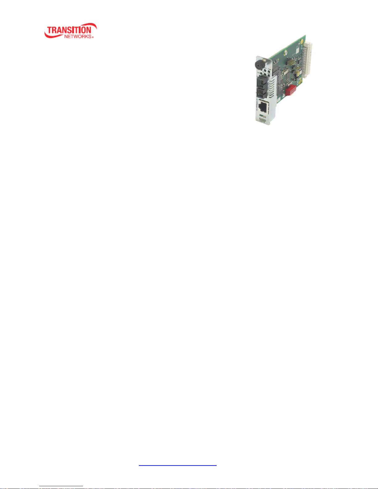
CBFTF10xx-1xx
Slide-in-Module Media Converter
• Extend network distance up to 120 km with an SFP module
• Convert 10/100 on copper to straight 100 on fiber
• Half or Full-Duplex on both ports
• Fully manageable
• Auto-Negotiation and AutoCross™
• Link Pass Through (LPT) and Far-End-Fault (FEF)
• Automatic Link Restoration
• Field Upgradeable Firmware
• Can be used with any Point System™ Chassis
• Bridging media converters provide conversion and integration solutions for half- and full-duplex environments
Contents
Introduction .................................................................................................................................................. 1
Ordering Information .................................................................................................................................... 2
DIP Switch and Jumper Locations ............................................................................................................. 3
Installation .................................................................................................................................................... 3
Set 6-position DIP Switch (SW2) ............................................................................................................... 4
Hardware/Software Mode Jumper (J4) .................................................................................................... 5
Install the Slide-in-Module ....................................................................................................................... 5
Install the Twisted-Pair Copper Cable ...................................................................................................... 6
Install the Fiber Cable ............................................................................................................................... 6
Operation ...................................................................................................................................................... 7
Status LEDs ............................................................................................................................................... 7
Product Features ...................................................................................................................................... 8
Cable Specifications ................................................................................................................................ 10
Technical Specifications .............................................................................................................................. 12
Troubleshooting .......................................................................................................................................... 13
Contact Us ................................................................................................................................................... 14
Compliance Information ............................................................................................................................. 14
Declaration of Conformity ...................................................................................................................... 14
CE Mark ................................................................................................................................................... 14
Record of Revisions ..................................................................................................................................... 15
Introduction
Transition Networks CBFTF10xx-10x two-port Ethernet/Fast Ethernet bridging media converter connects
10Base-T Ethernet or 100Base-TX Fast Ethernet twisted-pair copper network devices to network devices
on a 100Base-FX Fast Ethernet fiber network.
The CBFTF10xx-10x provides an interface between 10/100Base-TX ports and 100Base-FX ports, allowing
you to integrate fiber optic cabling into 10/100Base-TX copper environments. Operating at Layer 2, this
converter not only converts copper to fiber, but it also does Rate Conversion, converting 10/100 copper
to 100Base fiber.
33403 Rev. E https://www.transition.com Page 1 of 15
Page 2

Transition Networks CBFTF10xx-1xx User Guide
SKU
Description
10/100BASE-TX (RJ-45) [100 m/328 ft.] to
100BASE-FX 1300nm MM (ST) [2 km/1.2 mi.] Link Budget: 11.0 dB
10/100BASE-TX (RJ-45) [100 m/328 ft.] to
100BASE-FX 1300nm MM (SC) [2 km/1.2 mi.] Link Budget: 11.0 dB
10/100BASE-TX (RJ-45) [100 m/328 ft.] to
100BASE-FX 1300nm MM (LC) [2 km/1.2 mi.] Link Budget: 11.0 dB
10/100BASE-TX (RJ-45) [100 m/328 ft.] to
100BASE-FX 1310nm SM (SC) [20 km/12.4 mi.] Link Budget: 16.0 dB
10/100BASE-TX (RJ-45) [100 m/328 ft.] to
100BASE-FX 1310nm SM (LC) [20 km/12.4 mi.] Link Budget: 17.3 dB
CBFTF1040-105
10/100BASE-TX (RJ-45) [100 m/328 ft.] to 100BASE-X SFP Slot (empty)
Single Fiber
Products
10/100BASE-TX (RJ-45) [100 m/328 ft.] to 100BASE-FX 1310nm TX/1550nm RX
single fiber SM (SC) [20 km/12.4 mi.] Link Budget: 19.0 dB
10/100BASE-TX (RJ-45) [100 m/328 ft.] to 100BASE-FX 1550nm TX/1310nm RX
single fiber SM (SC) [20 km/12.4 mi.] Link Budget: 19.0 dB
Ordering Information
CBFTF1011-105
CBFTF1013-105
CBFTF1039-105
CBFTF1014-105
CBFTF1019-105
Recommended use in pairs
CBFTF1029-105
CBFTF1029-106
*Typical maximum cable distance. Actual distance is dependent upon the physical characteristics of the
network installation.
** CBFTF1029-105 and CBFTF1029-106 are intended to be installed in the same network where one is
the local converter and the other is the remote converter.
33403 Rev. E https://www.transition.com Page 2 of 15
Page 3

Transition Networks CBFTF10xx-1xx User Guide
DIP Switch and Jumper Locations
PCB 11293 Rev. A is shown below.
Installation
CAUTION: Wear a grounding device and observe electrostatic discharge precautions when setting the 6-
position DIP switch. Failure to observe this caution could result in damage to the media converter.
33403 Rev. E https://www.transition.com Page 3 of 15
Page 4
Transition Networks CBFTF10xx-1xx User Guide
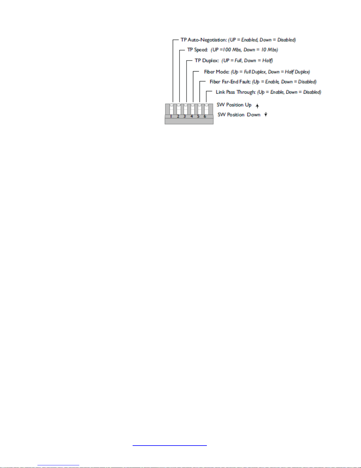
Set 6-position DIP Switch
(SW2)
The 6-position DIP switch (SW2) is located
located on the edge of the PCB. Use a
small flat blade screwdriver to set the
recessed switches. See below for the
individual switch settings.
1. Auto-Negotiation
up Enables Auto-Negotiation on the copper port.
Advertises the setting of switches 2 and 3.
down Disables Auto-Negotiation on the copper port. Forces the setting of switches 2 and 3.
2. Speed (only functions whan Switch 1 is Down)
up 100 Mb/s operation on the copper port.
down 10 Mb/s operation on the copper port.
3. Copper Mode Duplex (only functions whan Switch 1 is Down)
up full duplex operation on the copper port.
down half duplex operation on the copper port.
(Parallel detection only with Auto-Negotiation enabled and linked to nonnegotiatingdevice)
up Parallel detects in IEEE standard half duplex.
down Non-standard full duplex.
4. Fiber Mode
up Forces full duplex operation on the fiber port.
down Forces half duplex operation on the fiber port.
5. Far-End Fault (FEF)
up FEF Enabled
down FEF Disabled
6. Link Pass Through (LPT)
up LPT Enabled
down LPT Disabled
33403 Rev. E https://www.transition.com Page 4 of 15
Page 5
Transition Networks CBFTF10xx-1xx User Guide
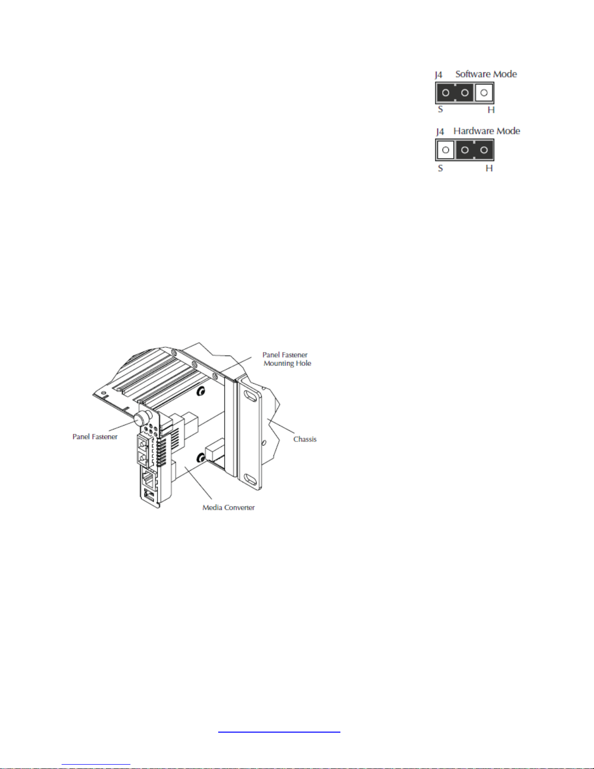
Hardware/Software Mode Jumper (J4)
The jumpers are located on the media converter circuit board. Use a small
needlenosed pliers or a similar tool to set the jumper.
The Hardware/Software jumper is labeled “H” for hardware and “S” for
software.
Software: The media converter mode is determined by the most-recently
saved on-board settings.
Hardware: The media converter mode is determined by the 6-position switch settings listed above.
Install the Slide-in-Module
To install the CBFTF10xx-105 media converter slide-in module:
1. Locate an empty installation slot on the PointSystem™ chassis.
2. Carefully slide the module into the installation slot, aligning the module with the installation guides.
3. Ensure that the module is firmly seated inside the chassis.
4. Push in and rotate the panel fastener screw to secure the module to the chassis front.
33403 Rev. E https://www.transition.com Page 5 of 15
Page 6

Transition Networks CBFTF10xx-1xx User Guide
Install the Twisted-Pair Copper Cable
Note: The AutoCross feature allows either MDI (straight-through) or MDI-X (crossover) cable
connections to be configured automatically, according to the network conditions.
1. Locate or build IEEE 803.2 compliant 10Base-T or 100Base-TX cable, with RJ-45 connectors installed
at both ends.
2. Connect the RJ-45 connector at one end of the cable to the RJ-45 port on the CBFTF10xx-10x media
converter.
3. Connect the RJ-45 connector at the other end of the cable to the RJ-45 port on the other device
(switch, workstation, etc.).
Install the Fiber Cable
1. Locate an IEEE 803.2 compliant 100Base-FX fiber cable with male, two-stranded TX to RX connectors
installed at both ends.
2. Connect the fiber cables to the CBFTF10xx-10x as described:
• Connect the male TX cable connector to the female TX port.
• Connect the male RX cable connector to the female RX port.
3. Connect the fiber cables to the other device (another media converter, hub, etc.) as described:
• Connect the male TX cable connector to the female RX port.
• Connect the male RX cable connector to the female TX port.
33403 Rev. E https://www.transition.com Page 6 of 15
Page 7

Transition Networks CBFTF10xx-1xx User Guide
Operation
Status LEDs
Use the status LEDs to monitor media converter operation in the network.
FDPX (Fiber Duplex)
ON = full duplex fiber connection.
OFF= half duplex fiber connection.
FLNK (Fiber Link)
ON = Fiber link connection.
Blinking = Fiber network activity.
PWR (Power)
ON = Power applied to chassis card.
TSPD (Twisted-Pair Speed)
ON = 100 Mb/s.
OFF = 10 Mb/s.
TDPX (Twisted Pair Duplex)
ON = full duplex copper connection.
OFF = half duplex copper connection.
TLNK (Twisted Pair Link)
ON = Copper link connection.
Blinking = Copper network activity.
33403 Rev. E https://www.transition.com Page 7 of 15
Page 8

Transition Networks CBFTF10xx-1xx User Guide
Product Features
AutoCross™
The AutoCross feature detects and configures the twisted-pair copper port on the CBFTF10xx-10x media
converter to the correct straight-through (MDI) or crossover (MDI-X) configuration. This feature allows
either MDI or MDI-X cable to connect the media converter to devices such as hubs, transceivers, or
network interface cards (NICs). (No operator intervention required.)
Link Pass-Through
The Link Pass-Through (LPT) feature allows the media converter to monitor both the fiber and copper RX
(receive) ports for loss of signal. In the event of a loss of an RX signal (1), the media converter will
automatically disable the TX (transmit) signal (2), thus, “passing through” the link loss (3). The far-end
device is automatically notified of the link loss (4), which prevents the loss of valuable data unknowingly
transmitted over an invalid link.
LPT with Valid Link ID: When a LPT condition occurs the Link/Activity LED for the port that still would
have a link up condition, but is being forced into a link down, blinks on and off every 2 seconds while
the LPT condition exists.
Far-end Fault
When a fault occurs on an incoming fiber link (1), the media converter transmits a Far-End Fault signal
on the outgoing fiber link (2). In addition, the Far-End Fault signal also activates the Link Pass-Through,
which, in turn, disables the link on the copper portion of the network (3) and (4).
Auto-Negotiation
The Auto-Negotiation feature allows the CBFTF10xx-10x media converter to automatically configure
itself to achieve the best possible mode of operation over a link. The media converter will broadcast its
speed (10 Mb/s or 100 Mb/s) and duplex capabilities (full or half) to the other devices and negotiates
the best mode of operation. Auto-Negotiation allows quick and easy installation because the optimal
link is established automatically. No user intervention is required to determine the best mode of
operation.
In a scenario where the media converter is linked to a non-negotiating device is a case where you may
want to disable Auto-Negotiation. In this instance, the mode of operation will drop to the least common
denominator between the two devices (e.g. 100 Mb/s, half duplex). Disabling this feature lets you force
the connection to the best mode of operation.
33403 Rev. E https://www.transition.com Page 8 of 15
Page 9

Transition Networks CBFTF10xx-1xx User Guide
Parallel Detection
Parallel detection is the method used to link when an auto negotiating port detects a link partner that is
in forced mode and therefore cannot participate in the auto negotiating process. Parallel Detection can
be set to IEEE Standard half duplex, or the non-standard full duplex. Switch settings for parallel
detection are valid in hardware or software mode, only when Auto-Negotiation is enabled.
Per the IEEE method, an auto negotiating port that detects a forced link partner should drop to the
detected speed (10Mbs or 100Mbs) and default to HALF DUPLEX.
The CBFTF-10xx-10x allows bypassing the IEEE method by setting the parallel detection default mode to
half or full duplex via DIP switch 3.
Full Duplex Network
In a full duplex network, maximum cable lengths are determined by the type of cables that are used. See
the cable specifications for the different CBFTF10xx-10x models.
Half duplex network (512-Bit Rule)
In a half duplex network, the maximum cable lengths are determined by the round trip delay limitations
of each Fast Ethernet collision domain. (A collision domain is the longest path between any two terminal
devices, e.g. a terminal, switch, or router.)
The 512-Bit Rule determines the maximum length of cable permitted by calculating the round-trip delay
in bit-times (BT) of a particular collision domain. If the result is less than or equal to 512 BT, the path is
good.
For more information on the 512-Bit Rule, see the white paper titled “Collision Domains” on-line at:
https://www.transition.com
.
SNMP
See the on-line documentation that comes with Transition Networks FocalPoint™ software for
applicable commands and usage.
Use SNMP at an attached terminal or at a remote location to monitor the converter by monitoring:
• Media converter power
• Serial and part number
• Port number
• Copper and fiber link status
• Copper and fiber duplex mode
• Copper port speed
• Hardware switch setting
Also, use SNMP to enter network commands that do the following:
• Enable/disable Auto-Negotiation on copper
• Force 10Mb/s or 100Mb/s on copper
• Force full duplex or half duplex on copper
• Force full duplex or half duplex on fiber
• Enable/disable Far-End Fault on fiber
• Enable/disable Link Pass Through
33403 Rev. E https://www.transition.com Page 9 of 15
Page 10

Transition Networks CBFTF10xx-1xx User Guide
Cable Specifications
The physical characteristics must meet or exceed the IEEE 802.3™ specifications.
Fiber Cable
Bit Error Rate: <10-9
Single mode fiber (recommended): 9 μm
Multimode fiber (recommended): 62.5/125 μm
Multimode fiber (optional): 100/140, 85/140, 50/125 μm
CBFTF1011-105, CBFTF1013-105 multimode
Fiber Optic Transmitter Power: min: -19.0 dBm max: -14.0 dBm
Fiber Optic Receiver Sensitivity: min: -30.0 dBm max: -14.0 dBm
Link Budget: 11.0 dB
CBFTF1012-105 single mode
Fiber-optic Transmitter Power: min: -18.0 dBm max: -7.0 dBm
Fiber-optic Receiver Sensitivity: min: -32.0 dBm max: -3.0 dBm
Link Budget: 14.0 dB
CBFTF1014-105 single mode
Fiber-optic Transmitter Power: min: -15.0 dBm max: -8.0 dBm
Fiber-optic Receiver Sensitivity: min: -31.0 dBm max: -8.0 dBm
Link Budget: 16.0 dB
CBFTF1015-105 single mode
Fiber-optic Transmitter Power: min: -5.0 dBm max: -2.0 dBm
Fiber-optic Receiver Sensitivity: min: -34.0 dBm max: -7.0 dBm
Link Budget: 29.0 dB
CBFTF1016-105 single mode
Fiber-optic Transmitter Power: min: -4.0dBm max: -2.0 dBm
Fiber-optic Receiver Sensitivity: min: -36.0 dBm max: -3.0 dBm
Link Budget: 32.0 dB
CBFTF1017-105 single mode
Fiber-optic Transmitter Power: min: -5.0 dBm max: -0.0 dBm
Fiber-optic Receiver Sensitivity: min: -34.0dBm max: -7.0 dBm
Link Budget: 29.0 dB
CBFTF1019-105 single mode
Fiber-optic Transmitter Power: min: -15.2 dBm max: -8.0 dBm
Fiber-optic Receiver Sensitivity: min: -32.5 dBm max: -3.0 dBm
Link Budget: 17.3 dB
CBFTF1029-105, CBFTF1029-106 single mode
Fiber-optic Transmitter Power: min: -14.0 dBm max: -8.0 dBm
Fiber-optic Receiver Sensitivity: min: -33.0 dBm max: -3.0 dBm
Link Budget: 19.0 dB
33403 Rev. E https://www.transition.com Page 10 of 15
Page 11

Transition Networks CBFTF10xx-1xx User Guide
CBFTF1029-107, CBFTF1029-108 single mode
Fiber-optic Transmitter Power: min: -8.0 dBm max: -3.0 dBm
Fiber-optic Receiver Sensitivity: min: -33.0 dBm max: -3.0 dBm
Link Budget: 25.0 dB
CBFTF1035-105 multimode
Fiber-optic Transmitter Power: min: 0.0 dBm max: 5.0 dBm
Fiber-optic Receiver Sensitivity: min: -36.0 dBm max: -3.0 dBm
Link Budget: 36dB
CBFTF1039-105 multimode
Fiber-optic Transmitter Power: min: -19.0 dBm max: -14.0 dBm
Fiber-optic Receiver Sensitivity: min: -30.0 dBm max: -14.0 dBm
Link Budget: 11dB
Copper Cable maximum cable distance: 100 meters
Category 3: (Minimum requirement for 10 Mb/s operation)
Gauge 24 to 22 AWG
Attenuation 11.5 dB/100m @ 5-10 MHz
Category 5: (Minimum requirement for 100 Mb/s operation)
Gauge 24 to 22 AWG
Attenuation 22.0 dB /100m @ 100 MHz
• Straight-through (MDI) or crossover (MDI-X) twisted-pair cable must be used.
• Shielded twisted-pair (STP) or unshielded twisted-pair (UTP) may be used.
• Pins 1&2 and 3&6 are the two active pairs in an Ethernet network .
• Use only dedicated wire pairs for the active pins (e.g., blue/white & white/blue, orange/white &
white/orange, etc.)
• Do not use flat or silver satin wire.
33403 Rev. E https://www.transition.com Page 11 of 15
Page 12

Transition Networks CBFTF10xx-1xx User Guide
Technical Specifications
For use with Transition Networks Model CBFTF10xx-10x or equivalent.
Standards IEEE Std. 802.3u, 802.3x
Data Rate 10 Mbps; 100 Mbps
Weight 1 lbs. [0.45 kg]
Power Consumption 3 watts
Max. Packet Size: 2048 bytes untagged bytes
2044 bytes tagged bytes
Filtering & Forwarding 14,880 pps for Ethernet; Rate 148,800 pps for Fast Ethernet
Dimensions Width: 0.86” [22 mm] x Depth: 5.0” [127 mm] x Height: 3.4” [86 mm]
Power Consumption 4.0 Watts
Environment See chassis specifications
Regulatory Compliance FCC Class A, CISPR22/EN55022
Class A, EN55024, EN61000, CE Mark
MTBF Greater than 250,000 hours (MIL-HDBK-217F)
Greater than 687,500 hours (Bellcore7 V5.0)
Warranty Lifetime
For current information on the CBFTF10xx-10x see the online user guide at https://www.transition.com
Product is certified by the manufacturer to comply with DHHS Rule 21/CFR, Subchapter J applicable at
the date of manufacture.
WARNING: Visible and invisible laser radiation when open. Do not stare into the beam or view the beam
directly with optical instruments. Failure to observe this warning could result in an eye injury or
blindness.
WARNING: Use of controls, adjustments or the performance of procedures other than those specified
herein may result in hazardous radiation exposure.
The fiber optic transmitters on this device meet Class I Laser safety requirements per IEC-825/CDRH
standards and comply with 21 CFR1040.10 and 21CFR1040.11.
*MTBF is estimated using the predictability method. This method is based on MIL-217F and Bellcore
standards at 40°C ambient temperature, typical enclosure heat rise of 10°C, and nominal operating
conditions and parameters. Installation and configuration specific MTBF estimates are available upon
request. Contact Technical Support.
CAUTION: Copper based media ports, e.g., Twisted Pair (TP) Ethernet, USB, RS232, RS422, RS485, DS1,
DS3, Video Coax, etc., are intended to be connected to intrabuilding (inside plant) link segments that are
not subject to lightening transients or power faults. Copper based media ports, e.g., Twisted Pair (TP)
Ethernet, USB, RS232, RS422, RS485, DS1, DS3, Video Coax, etc., are NOT to be connected to interbuilding (outside plant) link segments that are subject to lightening transients or power faults.
Failure to observe this caution could result in damage to equipment.
.
33403 Rev. E https://www.transition.com Page 12 of 15
Page 13

Transition Networks CBFTF10xx-1xx User Guide
Troubleshooting
If the media converter fails, isolate and correct the fault by determining the answers to the following
questions and then taking the indicated action:
1. Is the PWR (power) LED lit?
NO
• Is the power cord properly installed in the media converter and at the external power source?
• Does the external power source active?
• Contact Technical Support; see Contact Us below.
YES
• Proceed to step 2.
2. Is the TLNK (copper link) LED lit?
NO
• Check the copper cables for proper connection and pin assignment.
• Contact Technical Support; see Contact Us below.
YES
• Proceed to step 3.
3. Is the FLNK (fiber-pair link) LED lit?
NO
• Check the fiber cables for proper connection.
• Verify that the TX and RX cables are connected to the RX and TX ports, respectively on the
100Base-FX device.
• Contact Technical Support; see Contact Us below.
YES
• Proceed to step 4.
4. Is the TPSD (twisted-pair speed) LED lit?
NO
• Check the copper cables for proper connection.
• Off = The media converter has selected 10Mb/s operation.
• If the speed is not correct, disconnect and reconnect the twisted pair cable to restart the
initialization process.
• Contact Technical Support; see Contact Us below.
YES
• On = The media converter has selected 100Mb/s operation.
• If the speed is not correct, disconnect and reconnect the twisted pair cable to restart the
initialization process.
• Contact Tech Support; see Contact Us below.
33403 Rev. E https://www.transition.com Page 13 of 15
Page 14

Transition Networks CBFTF10xx-1xx User Guide
Contact Us
Technical Support: Technical support is available 24-hours a day
US and Canada: 1-800-260-1312
International: 00-1-952-941-7600
Main Office
tel: +1.952.941.7600 | toll free: 1.800.526.9267 | fax: 952.941.2322
sales@transition.com | techsupport@transition.com | customerservice@transition.com
Address
Transition Networks
10900 Red Circle Drive
Minnetonka, MN 55343, U.S.A.
Web: https://www.transition.com
Compliance Information
Declaration of Conformity
CE Mark
FCC regulations
This equipment has been tested and found to comply with the limits for a Class A digital device, pursuant to Part
15 of the FCC rules. These limits are designed to provide reasonable protection against harmful interference when
the equipment is operated in a commercial environment. This equipment generates, uses and can radiate radio
33403 Rev. E https://www.transition.com Page 14 of 15
Page 15

Transition Networks CBFTF10xx-1xx User Guide
A
6/5/08
Initial release.
Added notes to DIP switch section. Added copper base media cautions statement to tech spec
section. Added CBFTF1012-105.
E
10/14/16
UpdatedDIP switch and jumper information; updated format and contact information.
frequency energy and, if not installed and used in accordance with the instruction manual, may cause harmful
interference to radio communications.
Operation of this equipment in a residential area is likely to cause harmful interference, in which case the user will
be required to correct the interference at the user's own expense.
Canadian regulations
This digital apparatus does not exceed the Class A limits for radio noise for digital apparatus set out on the radio
interference regulations of the Canadian Department of Communications.
Le présent appareil numérique n'émet pas de bruits radioélectriques dépassant les limites applicables aux
appareils numériques de la Class A prescrites dans le Règlement sur le brouillage radioélectrique édicté par le
ministère des Communications du Canada.
European regulations
Warning This is a Class A product. In a domestic environment this product may cause radio interference in which
case the user may be required to take adequate measures.
Achtung ! Dieses ist ein Gerät der Funkstörgrenzwertklasse A. In Wohnbereichen können bei Betrieb dieses
Gerätes Rundfunkstörungen auftreten. In diesem Fäll is der Benutzer für Gegenmaßnahmen verantwortlich.
Attention !
Ceci est un produit de Classe A. Dans un environment domestique, ce produit risque de créer des interférences
radioélectriques, il appartiendra alors à l'utilsateur de prende les measures spécifiques appropriées.
In accordance with European Union Directive 2002/96/EC of the European Parliament and of the
Council of 27 January 2003, Transition Networks will accept post usage returns of this product for
proper disposal. The contact information for this activity can be found in the 'Contact Us' portion of
this document.
CAUTION: RJ connectors are NOT INTENDED FOR CONNECTION TO THE PUBLIC TELEPHONE NETWORK. Failure to
observe this caution could result in damage to the public telephone network.
Der Anschluss dieses Gerätes an ein öffentlickes Telekommunikationsnetz in den EGMitgliedstaaten verstösst
gegen die jeweligen einzelstaatlichen Gesetze zur Anwendung der Richtlinie 91/263/EWG zur Angleichung der
Rechtsvorschriften der Mitgliedstaaten über Telekommunikationsendeinrichtungen einschliesslich der
gegenseitigen Anerkennung ihrer Konformität.
Record of Revisions
Rev Date Notes
B 11/21/08 Switch positions 2 and 3 swapped: Speed and Duplex. Added part # SBFTF1040-105
C 6/29/10
D 10/14/10 Corrected link budgets on CBFTF1015, 16, 17-105.
Trademark notice: All trademarks and registered trademarks are the property of their respective owners.
Copyright restrictions: © 2008-2016 Transition Networks. All rights reserved. No part of this work may be reproduced or used
in any form or by any means - graphic, electronic or mechanical - without written permission from Transition Networks.
33403 Rev. E https://www.transition.com Page 15 of 15
 Loading...