

Transition Networks CBFTF1011-150, CBFTF1015-150, CBFTF1013-150, CBFTF1014-150, CBFTF1018-150 User Manual
...Page 1
* Typical maximum cable distance. (Actual distance is dependent upon the
physical characteristics of the network.) (TX) = transmit (RX) = receive
** SBFTF1029-
150 and SBFTF1029-151 are intended to be installed in the same
network where one is the local converter and the other is the remote
converter.
*** SBFTF1029-
152 and SBFTF1029-153
are intended to be installed in the same
network where one is the local
converter and the other is the remote
converter.
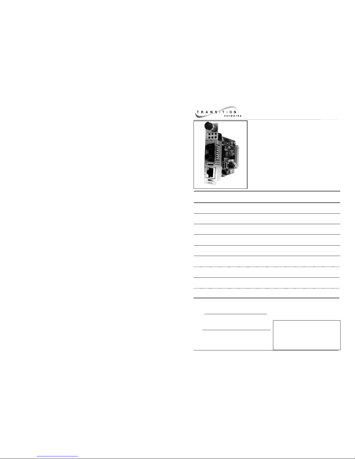
USER’S GUIDE
CBFTF10xx-15x
Slide-in-Module Media Converter
• Copper to Fiber
• 10/100 Bridging (2-Port)
• 10Base-T/100Base-TX to 100Base-FX
The CBFTF10xx-15x 2-port Ethernet/Fast Ethernet
bridging Media Converter is designed to be
installed in a Transition Networks PointSystem™
chassis and connects 10Base-T Ethernet or
100Base-TX Fast Ethernet twisted-pair copper
network devices to network devices on a 100BaseFX Fast Ethernet fiber network.
CBFTF1029-150** RJ-45
100 m (328 ft)*
SC, 1310 mn (TX)/1550 nm (RX)
singlemode, 20 km (12.4 miles)*
CBFTF1029-151** RJ-45
100 m (328 ft)*
SC, 1550 mn (TX)/1310 nm (RX)
singlemode, 20 km (12.4 miles)*
CBFTF1029-152*** RJ-45
100 m (328 ft)*
SC, 1310 mn (TX)/1550 nm (RX)
singlemode, 40 km (24.8 miles)*
CBFTF1029-153*** RJ-45
100 m (328 ft)*
SC, 1550 mn (TX)/1310 nm (RX)
singlemode, 40 km (24.8 miles)*
Part Number Port One - Copper
10Base-T/100Base-TX
Port Two - Duplex Fiber-Optic
100Base-FX
CBFTF1011-150 RJ-45
100 m (328 ft)*
ST, 1300 nm multimode
2 km (1.2 miles)*
CBFTF1013-150 RJ-45
100 m (328 ft)*
SC, 1300 nm multimode
2 km (1.2 miles)*
CBFTF1014-150 RJ-45
100 m (328 ft)*
SC, 1310 nm singlemode
20 km (12.4 miles)*
CBFTF1015-150 RJ-45
100 m (328 ft)*
SC, 1310 nm singlemode
40 km (24.8 miles)*
CBFTF1018-150 RJ-45
100 m (328 ft)*
MT-RJ, 1300 nm multimode
2 km (1.2 miles)*
Installation . . . . . . . . . . . . . . . . . .2
Operation . . . . . . . . . . . . . . . . . . .5
Cable Specifications . . . . . . . . . . .8
Technical Specifications . . . . . . . .9
Fault Isolation and Correction . .10
Compliance Information . . . . . . .12
Page 2
2
CBFTF10xx-15x
Tech Support: 800-260-1312 International: 952-941-7600 7am-6pm CST (GMT-6:00)
INSTALLATION
CAUTION: Wear a grounding device and observe electrostatic discharge
precautions when setting the 4-position switch and the jumper(s) and when
installing the Slide-in-Module. Failure to observe this caution could result in
damage to, and subsequent failure of, the Media Converter.
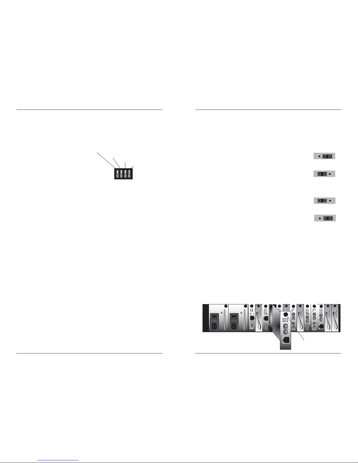
Set the 4-Position Switch
The 4-position switch is located on the
side of the Media Converter. Use a
small flatblade screwdriver or a similar
device to set the recessed switches.
Refer to the drawing for the locations
of the four individual switches.
1. Auto-Negotiation
UP Enables Auto-Negotiation on the copper port.
Advertises 100 Mb/s full-duplex and half duplex,
and 10 Mb/s full-duplex and half duplex.
DOWN Disables Auto-Negotiation on the copper port.
2. Copper Mode
(Applies only if switch 1 is DOWN.)
UP Forces full-duplex operation on the copper port.
DOWN Forces half-duplex operation on the copper port.
3. Speed
(Applies only if switch 1 is DOWN.)
UP Forces 100 Mb/s operation on the copper port.
DOWN Forces 10 Mb/s operation on the copper port.
4. Fiber Mode
UP Forces full-duplex operation on the fiber port.
DOWN Forces half-duplex operation on the fiber port.
Speed (UP=100Mb/s)
Copper Mode (UP=Full-Duplex)
Auto-Negotiation (UP=Enabled)
Fiber Mode
(UP=Full-Duplex)
1234
techsupport@transition.com -- Select the “Transition Now” Link for a Live Web Chat
3
INSTALLATION -- Continued
Set the Jumpers
The jumpers are located on the Media Converter circuit board. Use small
needle-nosed pliers or a similar device to set the jumper.
The Hardware/Software jumper is labeled “H” for hardware and “S” for
software (see the drawing below).
Hardware The Media Converter mode is determined by
the 4-position switch settings listed above.
Software The Media Converter mode is determined by
the most-recently saved, on-board
microprocessor settings.
The Far-End Fault jumper is labeled “FE” for enable Far-End Fault and “FD”
for disable Far-End Fault (see the drawing below).
Enable A fault on the fiber link causes the Media
Converter to transmit a Far-End Fault signal.
Disable No Far-End Fault signal is transmitted when a
fault occurs.
Software Mode
Hardware Mode
S
H
S
H
Disable Far-End Faul
t
Enable Far-End Fault
FE FD
FE FD
Installing the Slide-In-Module
CAUTION: Slots in the PointSystem™ Chassis without a Slide-in-Module
installed MUST have a protective plate covering the empty slot for Class A
and/or Class B compliance.
To install the CGETF10xx-15x Media Converter Slide-in-Module:
1. Locate an empty installation slot on the PointSystem™ Chassis.
2. Carefully slide the Slide-in-Module into the installation slot, aligning the
Slide-in-Module with the installation guides.
3. Ensure that the Slide-in-Module is firmly seated against the back of the
chassis.
4. Secure the Slide-in-Module by securing the panel fastener screw
(attached to the Slide-in-Module) to the chassis front.
CFMFF100
10BASE-2
CECF100
CFMFF100
0
50½
Link Alert
E
D
CETCF100
CFETF100
CFETF110
CFMFF100
LA
PWR
RXF
RXC
LNK
COL
SPD
PWR
FRX
CRX
FLNK
CLNK
SPD
PWR
FRX
CRX
FLNK
CLNK
10/100TX
RX
TX
10/100SX
100BASE-TX
RX
TX
100BASE-FX
Link Alert
E
D
0
50½
LA
PWR
RXF
RXC
LNK
COL
LKS
PWR
LKM
10BASE-2
10BASE-FL
10BASE-T
LKS
PWR
LKM
LKS
PWR
LKM
Multimode
Singlemode
TX
RX
TX
RX
Multimode
Singlemode
TX
RX
TX
RX
Multimode
Singlemode
TX
RX
TX
RX
I
0
TERM
INIT
RX
TX
LNK
PWR
CPSMM120
SERIAL
10BASE-T
R
E
S
E
T
I
0
Panel Fastener Screw
Page 3
4
CBFTF10xx-15x
Tech Support: 800-260-1312 International: 952-941-7600 7am-6pm CST (GMT-6:00)
INSTALLATION -- Continued
Install the Twisted-Pair Copper Cable
1. Locate or build IEEE 803.2™ compliant 10Base-T or 100Base-TX cables,
with straight-through RJ-45 cable, and with straight-through RJ-45
connectors installed at both ends.
2. Connect the RJ-45 connector at one end of the cable to the RJ-45 port
connector on the Media Converter.
3. Connect the RJ-45 connector at the other end of the cable to the RJ-45
port connector on the other device (switch, workstation, etc.).
NOTE: The MDI (straight-through) or MDI-X (crossover) cable connection is
configured automatically, according to the network conditions.
RJ-45 port
on the Media
Converter
RJ-45 port
on the other device
(switch, work station, etc.)
Install the Fiber Cable
1. Locate or build IEEE 803.2™ compliant 100Base-FX fiber cable with
male, two-stranded TX to RX connectors installed at both ends.
2. Connect the fiber cables to the CBFTF10xx-15x Media Converter as
described:
• Connect the male TX cable connector the female TX connector.
• Connect the male RX cable connector to the female RX connector.
3. Connect the fiber cables to the other device (another Media Converter,
hub, etc.) as described:
• Connect the male TX cable connector the female RX connector.
• Connect the male RX cable connector to the female TX connector.
Connect the fiber cable
to the Media Converter
as shown.
Connect the fiber cable
to the other device
(media converter,
hub, etc.) as shown
RX
TX
RX
TX
techsupport@transition.com -- Select the “Transition Now” Link for a Live Web Chat
5
INSTALLATION -- Continued
Power the Media Converter
The CBFTF10xx-15x Slide-in-Module Media Converter is powered through the
Point System™ chassis.
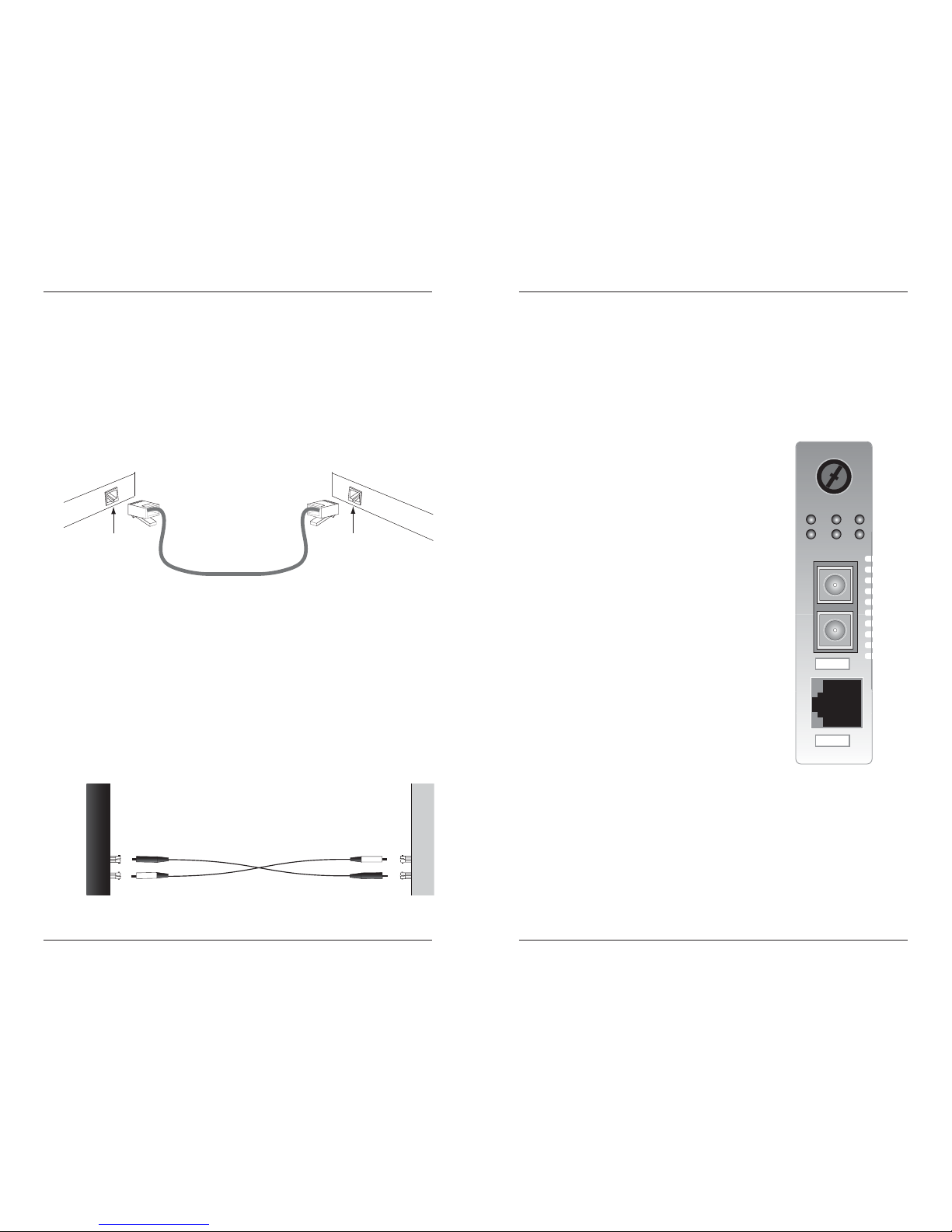
OPERATION
Status LEDs
Use the status LEDs to monitor the Media
Converter and the network connections.
FDPX (Fiber Duplex)
ON = full-duplex fiber connection.
Blinking = half-duplex fiber connection.
FLNK (Fiber Link)
ON = fiber link connection.
Blinking = fiber network activity.
PWR (Power)
ON = connection to external AC power.
TSPD (Twisted-Pair Speed)
ON = 100 Mb/s.
Blinking = 10 Mb/s.
TDPX (Twisted-Pair Duplex)
ON = full-duplex copper connection.
LED off = half-duplex copper connection.
TLKN(Twisted-Pair Link)
ON = copper link connection.
Blinking = copper network activity.
CBFTF150
PWRFDPX FLNK
TLNKTSPD TDPX
RX
TX
100Base-FX
10/100Base-TX
Page 4

6
CBFTF10xx-15x
Tech Support: 800-260-1312 International: 952-941-7600 7am-6pm CST (GMT-6:00)
OPERATION - Continued
Product Features
Auto-Negotiation
The Auto-Negotiation feature allows the Media Converter to be used with
10Base-T and 100Base-TX twisted-pair ports. Using Auto-Negotiation, the
Media Converter brings up the copper links in the highest speed and mode
possible for all the attached network devices.
If selected, Auto-Negotiation allows a twisted-pair link to become operational
only after the Auto-Negotiation function matches network speed capabilities
at both ends of the twisted-pair copper segment.
Autocross
The AutoCross™ feature, when selected, allows either straight-through (MDI)
or crossover (MDI-X) cables to be used when connecting to 10Base-TX or
100Base-TX devices, such as hubs, transceivers, or network interface cards
(NICs). AutoCross determines the characteristics of the cable connection and
automatically configures the unit to link up, regardless of the cable
configuration. (This feature does not require operator intervention.)
Far-End Fault
When the Far-End Fault feature is activated, a fault on an incoming fiber link
causes the Media Converter to transmit a Far-End Fault signal on the outgoing
fiber link. In addition the Far-End Fault signal also activates the Link PassThrough, which, in turn, disables the link on the copper portion of the
network.
Fiber
Copper
Copper
(Sends a Far-End
Fault)
Media Converter
Media Converter
Fiber
Copper
Copper
Media Converter
(Sends a Far-End
Fault)
Media Converter
100Base-TX
Device
100Base-TX
Device
100Base-FX
Device
100Base-FX
Device
techsupport@transition.com -- Select the “Transition Now” Link for a Live Web Chat
7
OPERATION - Continued
Product Features - Continued
Full-Duplex Network
In a full-duplex network, maximum cable lengths are determined by the type
of cables that are used. See page 1 (front cover) for the cable specifications
for the different CBFTF10xx-15x models.
The 512-Bit Rule does not apply in a full-duplex network.
Half-Duplex Network (512-Bit Rule)
In a half-duplex network, the maximum cable lengths are determined by the
round trip delay limitations of each Fast Ethernet collision domain. (A
collision domain is the longest path between any two terminal devices, e.g. a
terminal, switch, or router.)
The 512-Bit Rule determines the maximum length of cable permitted by
calculating the round-trip delay in bit-times (BT) of a particular collision
domain. If the result is less than or equal to 512 BT, the path is good.
For more information on the 512-Bit Rule, see the white paper titled “Collision
Domains” on the Transition Networks website at:
http://www.transition.com/learning/whitepapers/colldom_wp.htm
Using SNMP
See the on-line documentation that comes with Transition Networks
FocalPoint™ software for applicable commands and usage.
Use SNMP at an attached terminal or at a remote location to monitor the
Media Converter by monitoring:
•
Media Converter power
• Copper and f
iber link status
•
Copper and fiber duplex mode
•
Copper port speed
•
Hardware switch setting
Also, use SNMP to enter network commands that:
•
Enable/disable Auto-Negotiation on copper
•
Force 10Mb/s or 100Mb/s on copper
•
Force full-duplex or half-duplex on copper
•
Force full-duplex or half-duplex on fiber
•
Enable/disable Far-End Fault on fiber
Page 5

8
CBFTF10xx-15x
Tech Support: 800-260-1312 International: 952-941-7600 7am-6pm CST (GMT-6:00)
CABLE SPECIFICATIONS
The physical characteristics must meet or exceed IEEE 802.3™ specifications.
Fiber Cable
Bit Error Rate: <10-9
Singlemode fiber (recommended): 9 µm
Multimode fiber (recommended): 62.5/125 µm
Multimode fiber (optional): 100/140, 85/140, 50/125 µm
CBFTF1011-150, CBFTF1013-150 multimode
Fiber Optic Transmitter Power: min: -19.0 dBm max: -14.0 dBm
Fiber Optic Receiver Sensitivity: min: -30.0 dBm max: -14.0 dBm
Link Budget: 11.0 dB
CBFTF1014-150 singlemode
Fiber-optic Transmitter Power: min: -15.0 dBm max: -8.0 dBm
Fiber-optic Receiver Sensitivity: min: -31.0 dBm max: -8.0 dBm
Link Budget: 16.0 dB
CBFTF1015-150 singlemode
Fiber-optic Transmitter Power: min: -8.0 dBm max: -2.0 dBm
Fiber-optic Receiver Sensitivity: min: -34.0 dBm max: -7.0 dBm
Link Budget: 26.0 dB
CBFTF1018-150 multimode
Fiber-optic Transmitter Power: min: -19.0 dBm max: -14.0 dBm
Fiber-optic Receiver Sensitivity: min: -30.0 dBm max: -14.0 dBm
Link Budget: 11.0 dB
CBFTF1029-150, CBFTF1029-151 singlemode
Fiber-optic Transmitter Power: min: -13.0 dBm max: -6.0 dBm
Fiber-optic Receiver Sensitivity: min: -32.0 dBm max: -3.0 dBm
Link Budget: 19.0 dB
CBFTF1029-152, CBFTF1029-153 singlemode
Fiber-optic Transmitter Power: min: -8.0 dBm max: -3.0 dBm
Fiber-optic Receiver Sensitivity: min: -33.0 dBm max: -3.0 dBm
Link Budget: 25.0 dB
Copper Cable Maximum Cable Distance: 100 meters
Category 3: (May be used for 10 Mb/s operation)
Gauge 24 to 22 AWG
Attenuation 11.5 dB/100m @ 5-10 MHz
Category 5: (REQUIRED for 100 Mb/s operation)
Gauge 24 to 22 AWG
Attenuation 22.0 dB /100m @ 100 MHz
• Straight-Through Twisted-Pair cable must be used.
• Shielded Twisted-Pair (STP) OR Unshielded Twisted-Pair (UTP) may be used.
• Pins 1&2 and 3&6 are the two active pairs in an Ethernet network .
• Use only dedicated wire pairs for the active pins:
(e.g., blue/white & white/blue, orange/white & white/orange, etc.)
• Do not use flat or silver satin wire.
1
2
3
6
Straight-Through Cable
Twisted Pair #1
Twisted Pair #2
1
2
3
6
techsupport@transition.com -- Select the “Transition Now” Link for a Live Web Chat
9
TECHNICAL SPECIFICATIONS
For use with Transition Networks Model CBFTF10xx-15x or equivalent.
Standards IEEE 802.3™
Data Rate: 10 Mb/s, 100 Mb/s
Dimensions 3.4" x 4.7" x 0.87" (86 mm x 119 mm x 22 mm)
Weight 4 oz. (114 g) (approximate)
Power Consumption: 4.0 W
MTBF 629,677 hours (MIL217F2 V5.0) (MIL-HDBK-217F)
1,630,181 hours (Bellcore7 V5.0)
Packet Size: Unicast MAC address: 128K bytes (1 Mbit)
Maximum packet size: 1522 bytes
Memory: 1K bytes
Environment Tmra*: 0 to 60°C (32 to 140°F )
Storage Temp: -20 to 85°C (-4 to 185°F )
Humidity 10-90%, non condensing
Altitude 0-10,000 feet
Warranty Lifetime
*Manufacturer’s rated ambient temperature: Tmra range for this Slide-In-Module
depends on the physical characteristics and the installation configuration of the
Transition Networks PointSystem™ chassis in which this Slide-In-Module will be
installed.
Product is certified by the manufacturer to comply with DHHS Rule 21/CFR,
Subchapter J applicable at the date of manufacture.
CAUTION: Visible and Invisible Laser Radiation When Open. Do Not Stare
Into Beam Or View Directly With Optical Instruments.
CAUTION: Use of controls, adjustments or the performance of procedures
other than those specified herein may result in hazardous radiation exposure.
Page 6

10
CBFTF10xx-15x
Tech Support: 800-260-1312 International: 952-941-7600 7am-6pm CST (GMT-6:00)
FAULT ISOLATION AND RECOVERY
If the Media Converter fails, isolate and correct the failure by determining the
answers to the following questions and then taking the indicated action:
1. Is the power LED on the Media Converter illuminated?
NO
• Is the media converter inserted properly into the chassis?
• Is the power cord properly installed in the chassis and at the external
power source and does the external power source provide power?
• Contact Technical Support: US/Canada: 1-800-260-1312,
International: 00-1-952-941-7600.
YES
• Proceed to step 2.
2. Is the TLNK (twisted-pair link) LED illuminated?
NO
• Check the copper cables for proper connection and pin assignment.
• Contact Technical Support: US/Canada: 1-800-260-1312,
International: 00-1-952-941-7600.
YES
• Proceed to step 3.
3. Is the FLNK (fiber-pair link) LED illuminated?
NO
• Check the fiber cables for proper connection.
• Verify that the TX and RX cables are connected to the RX and TX
ports, respectively, on the 100Base-FX device.
• Contact Technical Support: US/Canada: 1-800-260-1312,
International: 00-1-952-941-7600.
YES
• Proceed to step 4.
4. Is the TSPD (twisted-pair speed) LED illuminated?
NO
• Check the copper cables for proper connection.
• Off = The Media Converter has selected 10Mb/s operation.
• If the speed is not correct, disconnect and reconnect the twisted pair
cable to restart the initialization process.
• Contact Technical Support: US/Canada: 1-800-260-1312,
International: 00-1-952-941-7600.
YES
• On = The Media Converter has selected 100Mb/s operation.
• If the speed is not correct, disconnect and reconnect the twisted pair
cable to restart the initialization process.
• Contact Technical Support: US/Canada: 1-800-260-1312,
International: 00-1-952-941-7600.
techsupport@transition.com -- Select the “Transition Now” Link for a Live Web Chat
11
CONTACT US
Technical Support
Technical support is avialable 7:00 AM - 6:00 PM CST (GMT -6:00)
US and Canada: 1-800-260-1312
International: 00-1-952-941-7600
Transition Now
Chat live via the Web with Transition Networks Technical Support.
Log onto www.transition.com and click the Transition Now link.
Web-Based Seminars
Transition Networks provides seminars via live web-based training.
Log onto www.transition.com and click the Learning Center link.
E-Mail
Ask a question anytime by sending an e-mail to our technical support staff.
techsupport@transition.com
Address
Transition Networks
6475 City West Parkway, Minneapolis, MN 55344, USA
telephone: 952-941-7600, toll free: 800-526-9267, fax: 952-941-2322
DECLARATION OF CONFORMITY
Name of Mfg: Transition Networks
6475 City West Parkway, Minneapolis MN 55344 USA
Model: CBFTF10xx-15x Series Media Converters
Part Number(s): CBFTF1011-150, CBFTF1013-150, CBFTF1014-150, CBFTF1015-150,
CBFTF1018-150, CBFTF1029-150, CBFTF1029-151, CBFTF1029-152,
CBFTF1029-153
Regulation: EMC Directive 89/336/EEC
Purpose: To declare that the
CBFTF10xx-15x
to which this declaration refers is
in conformity with the following standards.
EMC-CISPR 22:1985 Class A; EN 55022:1988 Class A; EN 50082-1:1992;
EN 60950 A4:1997; IEC 801.2, 801.3, and 801.4; IEC 950; 22 CFR subpart J
I, the undersigned, hereby declare that the equipment specified above conforms to the above
Directive(s) and Standard(s).
_August 8, 2002_____
Stephen Anderson, Vice-President of Engineering Date
Page 7

Trademark Notice
All trademarks and registered trademarks are the property of their respective owners.
Copyright Restrictions
© 2002-2003 Transition Networks.
All rights reserved. No part of this work may be reproduced or used in any form or by any
means - graphic, electronic, or mechanical - without written permission from Transition
Networks.
Printed in the U.S.A.
33226.B
COMPLIANCE INFORMATION
UL Listed
C-UL Listed (Canada)
CISPR22/EN55022 Class A
CE Mark
FCC Regulations
This equipment has been tested and found to comply with the limits for a class A digital
device, pursuant to part 15 of the FCC rules. These limits are designed to provide reasonable
protection against harmful interference when the equipment is operated in a commercial
environment. This equipment generates, uses, and can radiate radio frequency energy and, if
not installed and used in accordance with the instruction manual, may cause harmful
interference to radio communications. Operation of this equipment in a residential area is
likely to cause harmful interference, in which case the user will be required to correct the
interference at the user's own expense.
Canadian Regulations
This digital apparatus does not exceed the Class A limits for radio noise for digital apparatus
set out on the radio interference regulations of the Canadian Department of Communications.
Le présent appareil numérique n'émet pas de bruits radioélectriques dépassant les limites
applicables aux appareils numériques de la class A prescrites dans le Règlement sur le
brouillage radioélectrique édicté par le ministère des Communications du Canada.
European Regulations
Warning This is a Class A product. In a domestic environment this product may cause radio
interference in which case the user may be required to take adequate measures.
Achtung! Dieses ist ein Gerät der Funkstörgrenzwertklasse A. In Wohnbereichen können
bei Betrieb dieses Gerätes Rundfunkstörungen auftreten, in weichen Fällen der Benutzer für
entsprechende Gegenmaßnahmen werantwortlich ist.
Attention! Ceci est un produit de Classe A. Dans un environment domestique, ce produit
risque de créer des interférences radioélectriques, il appartiendra alors à l'utilsateur de
prende les measures spécifiques appropriées.
CAUTION: RJ connectors are NOT INTENDED FOR CONNECTION TO THE
PUBLIC TELEPHONE NETWORK. Failure to observe this caution could result in
damage to the public telephone network.
Der Anschluss dieses Gerätes an ein öffentlickes Telekommunikationsnetz in den EGMitgliedstaaten verstösst gegen die jeweligen einzelstaatlichen Gesetze zur Anwendung der
Richtlinie 91/263/EWG zur Angleichung der Rechtsvorschriften der Mitgliedstaaten über
Telekommunikationsendeinrichtungen einschliesslich der gegenseitigen Anerkennung ihrer
Konformität.
 Loading...