

Transition Networks CAPTF3329-100, CAPTF3314-100, CAPTF3313-100, CAPTF3329-101, CAPTF3329-102 User Manual
...Page 1
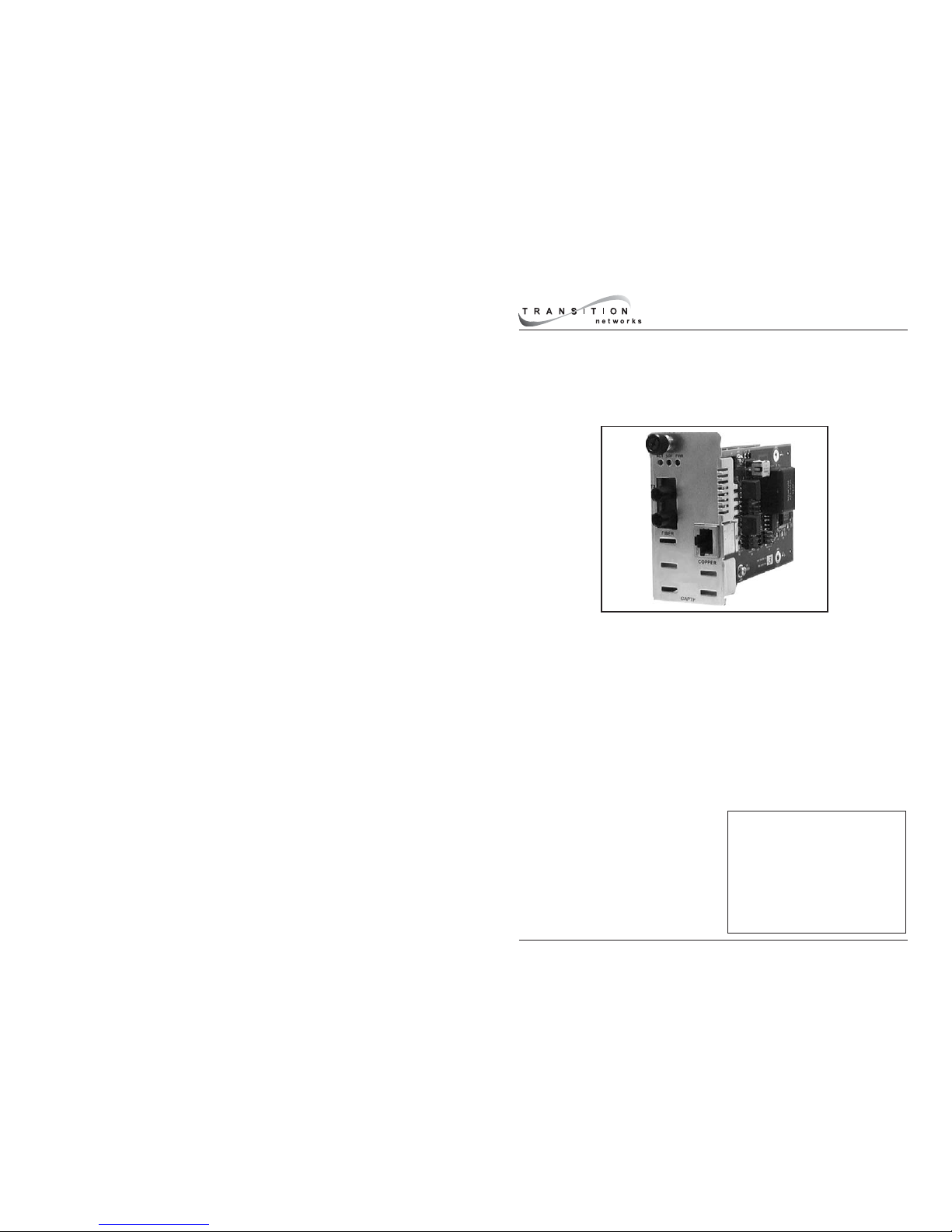
Transition Networks CAPTF33xx-1xx POTS to fiber-optic media converter connects
central-office voice-grade signals to distant POTS (Plain Old Telephone Service)
equipment using standard telephone signaling. It can extend, over fiber, the
distance between two voice path communication devices by up to 40 km using
either single mode or multimode fiber cable.
The CAPTF33xx-1xx provides audio transmission, caller ID, ringing at the distant
end and automatic ring-down. Two units are required to implement an end-to-end
system. An RJ-11 female connector provides the electrical interface between the
media converter and the telephone device.
The CAPTF33xx-1xx is designed to be installed in the Transition Networks
PointSystem™ chassis.
NOTE: The the stand alone version of
the media converter is SAPTF33xx-1xx.
For more information, see the
SAPTF33xx-1xx user’s guide on-line at:
www.transition.com.
CAPTF33xx-1xx in the Network . .4
Installation . . . . . . . . . . . . . . . . . .5
Operation . . . . . . . . . . . . . . . . . . .9
Cable Specifications . . . . . . . . . .11
RJ-11C Connector Specifications 12
Technical Specifications . . . . . . .12
Troubleshooting . . . . . . . . . . . . .13
Consumer Information . . . . . . . .14
Compliance Information . . . . . . .16
POTS to Fiber Optic
Slide-in-Module Media Converter
CAPTF33xx-1xx
User’s Guide
Page 2

2
CAPTF33xx-1xx
24-hour Technical Support: 1-800-260-1312 -- International: 00-1-952-941-7600
Unit A - CAPTF33xx-100
Unit A (CAPTF33xx-100) connects to a Central Office (CO) telephone line or a
PBX (Private Branch Exchange). It mimics a telephone device (Line-Side FXS) and
has the ability to detect ringing voltages. The available models are:
Product Number Port One - Copper
Twisted-Pair
Port Two - Duplex Fiber-Optic
CAPTF3311-100 RJ-11C connector
5 km (3.1 miles)*
ST connector, 1300 nm multimode
2 km (1.2 miles)*
CAPTF3313-100 RJ-11C connector
5 km (3.1 miles)*
SC connector, 1300 nm multimode
2 km (1.2 miles)*
CAPTF3314-100 RJ-11C connector
5 km (3.1 miles)*
SC connector, 1310 nm single mode
20 km (12.4 miles)*
CAPTF3315-100 RJ-11C connector
5 km (3.1 miles)*
SC connector, 1310 nm single mode
40 km (24.9 miles)*
* Typical maximum cable distance. Actual distance is dependent upon the
physical characteristics of the network installation.
Unit A is also available in single mode, single fiber models.
Product Number Port One - Copper
Twisted-Pair
Port Two - Fiber-Optic
Single Mode, Single Fiber
CAPTF3329-100 RJ-11C connector
5 km (3.1 miles)*
SC, 1310 nm (TX) / 1550 nm (RX),
20 km (12.4 miles)*
CAPTF3329-101 RJ-11C connector
5 km (3.1 miles)*
SC, 1550 nm (TX) / 1310 nm (RX),
20 km (12.4 miles)*
CAPTF3329-102 RJ-11C connector
5 km (3.1 miles)*
SC, 1310 nm (TX) / 1550 nm (RX),
40 km (24.9 miles)*
CAPTF3329-103 RJ-11C connector
5 km (3.1 miles)*
SC, 1550 nm (TX) / 1310 nm (RX),
40 km (24.9 miles)*
If this model is installed as Unit A: Install this model as Unit B:
CAPTF3329-100 CAPTF3329-111
CAPTF3329-101 CAPTF3329-110
CAPTF3329-102 CAPTF3329-113
CAPTF3329-103 CAPTF3329-112
The single mode, single fiber models are designed to be installed in pairs.
The table below lists which models should be installed in the same
network for the standard configuration (see page 4).:
3
techsupport@transition.com Click the “Transition Now” link for a live Web chat.
Unit B - CAPTF33xx-110
Unit B (CAPTF33xx-110), the reciprocal unit to unit A, connects to a telephone
device and mimics a Central Office (Customer-Side FXO). The available models
are:
* Typical maximum cable distance. Actual distance is dependent upon the
physical characteristics of the network installation.
Unit B is also available in single mode, single fiber models.
Product Number Port One - Copper
Twisted-Pair
Port Two - Fiber-Optic
Single Mode, Single Fiber
CAPTF3329-110 RJ-11C connector
5 km (3.1 miles)*
SC, 1310 nm (TX) / 1550 nm (RX),
20 km (12.4 miles)*
CAPTF3329-111 RJ-11C connector
5 km (3.1 miles)*
SC, 1550 nm (TX) / 1310 nm (RX),
20 km (12.4 miles)*
CAPTF3329-112 RJ-11C connector
5 km (3.1 miles)*
SC, 1310 nm (TX) / 1550 nm (RX),
40 km (24.9 miles)*
CAPTF3329-113 RJ-11C connector
5 km (3.1 miles)*
SC, 1550 nm (TX) / 1310 nm (RX),
40 km (24.9 miles)*
If this model is installed as Unit B: Install this model as the other Unit B:
CAPTF3329-110 CAPTF3329-111
CAPTF3329-111 CAPTF3329-110
CAPTF3329-112 CAPTF3329-113
CAPTF3329-113 CAPTF3329-112
The single mode, single fiber models are designed to be installed in pairs. The
table below lists which models should be installed in the same network for the
automatic ring-down configuration (see page 4).:
Product Number Port One - Copper
Twisted-Pair
Port Two - Duplex Fiber-Optic
CAPTF3311-110 RJ-11C connector
5 km (3.1 miles)*
ST connector, 1300 nm multimode
2 km (1.2 miles)*
CAPTF3313-110 RJ-11C connector
5 km (3.1 miles)*
SC connector, 1300 nm multimode
2 km (1.2 miles)*
CAPTF3314-110 RJ-11C connector
5 km (3.1 miles)*
SC connector, 1310 nm single mode
20 km (12.4 miles)*
CAPTF3315-110 RJ-11C connector
5 km (3.1 miles)*
SC connector, 1310 nm single mode
40 km (24.9 miles)*
Page 3
4
CAPTF33xx-1xx
24-hour Technical Support: 1-800-260-1312 -- International: 00-1-952-941-7600
CAPTF33xx-1xx in the Network
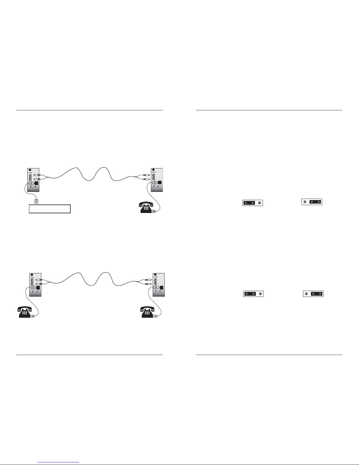
Standard Configuration
One Unit A device (CAPTF33xx-100) and one Unit B device (CAPTF33xx-110)
are required for the standard configuration. The Unit A device is connected to
the Central Office (CO) while the Unit B device is connected to a telephone
device.
Automatic Ring-Down Configuration
Automatic Ring Down (ARD) is a dedicated, point-to-point voice system. When
one telephone is taken off-hook, the other telephone rings, without the need to
dial. Two Unit B devices (CAPTF33xx-110), connected via the fiber ports, are
required for this mode of operation; with a telephone device at each end.
CAPTF33xx-100
Unit A -- Emulates
the telephone device
CAPTF33xx-110
Unit B -- Emulates the
Central Office (CO)
Central Office (CO)
CAPTF33xx-110
Unit B -- Emulates the
Central Office (CO)
CAPTF33xx-110
Unit B -- Emulates the
Central Office (CO)
5
techsupport@transition.com Click the “Transition Now” link for a live Web chat.
Installation
CAUTION: Wear a grounding device and observe electrostatic discharge
precautions when setting the jumpers. Failure to observe this caution could
result in damage to, and subsequent failure of, the media converter.
Set the Jumpers
Using small needle-nosed pliers or similar device, move the jumper to the
desired position. (Refer to the drawings below.)
Standard / Automatic Ring-Down
The jumper labeled “JP1” is used to switch between the Standard or Automatic
Ring-Down configuration and is located on the top circuit board of Unit B
(CAPTF33xx-110).
The drawing below illustrates the jumper settings.
• Set jumper JP1 on the Unit B device to the Standard setting when
using the Standard configuration (described on page 4).
• Set jumper JP1 on both Unit B devices to the Automatic Ring-Down
setting when using the Automatic Ring-Down configuration
(described on page 4).
US / EU Telephone Regulation
The jumper labeled “US EU” is used to switch between the US or EU
telephone configuration and is located on the top circuit board of Unit A
(CAPTF33xx-100). This feature is required to comply with the EU TBR21
telephone regulation. The jumper has been set at the factory to the US setting
as the default.
The drawing below illustrates the jumper settings.
• Set jumper “US EU” on the Unit A device to the US setting if the
device is to be used with US-based telephone systems.
• Set jumper “US EU” on the Unit A device to the EU setting if the
device is to be used with European-based telephone systems.
Standard
13
Automatic
Ring-Down
1
3
JP1
JP1
US Setting EU Setting
US EU US EU
Page 4

6
CAPTF33xx-1xx
24-hour Technical Support: 1-800-260-1312 -- International: 00-1-952-941-7600
Installation -- Continued
Install the Slide-In-Module
CAUTION: Wear a grounding device and observe electrostatic discharge
precautions when installing the media converter. Failure to observe this
caution could result in damage to, and subsequent failure of, the media
converter.
To install the CAPTF33xx-1xx media converter slide-in-module:
1. Locate an empty installation slot on the PointSystem™ chassis.
2. Carefully slide the slide-in-module into the installation slot, aligning the
module’s circuit board with the installation guides.
3. Ensure that the module is firmly seated inside the chassis.
4. Push in and rotate the attached attached panel fastener screw clockwise
to secure it the module to the chassis front.
10BASE-T
INPORT
OUTPORT
DB-9
12C
12C-1TERM
INIT
LKS
PWR
LKM
LKS
PWR
LKM
Multimode
Singlemode
TX
RX
TX
RX
LKF
PWR
RXF
RXC
LKC
SPD
PWR
FRX
CRX
FLNK
CLNK
RX
TX
100BASE-TX
RX
TX
100BASE-FX
Link Alert
E
D
0
50½
Multimode
Singlemode
TX
RX
TX
RX
LA
PWR
RXF
RXC
LNK
COL
10BASE-2
10BASE-FL
LKS
PWR
LKM
LKS
PWR
LKM
Multimode
Singlemode
TX
RX
TX
RX
Multimode
Singlemode
TX
RX
TX
RX
10BASE-T
10BASE-FL
Media
Conversion
Center
Power
In Use
1
Power
In Use
2
RX
TX
LNK
PWR
RESET
DB-9
Panel Fastener Screw
7
techsupport@transition.com Click the “Transition Now” link for a live Web chat.
Installation -- Continued
Install the Cable -- Standard Configuration
NOTE: Unit B must be configured for Standard Configuration (see page 4).
Fiber
1. Locate or build fiber cable with male, two-stranded TX to RX connectors
installed at both ends.
2. Connect the fiber cables to Unit A (CAPTF33xx-100) as described:
• Connect the male TX cable connector to the female TX port.
• Connect the male RX cable connector to the female RX port.
3. Connect the fiber cables to Unit B (CAPTF33xx-110) as described:
• Connect the male TX cable connector to the female RX port.
• Connect the male RX cable connector to the female TX port.
Copper
1. Locate or build copper cables with male, RJ11C connectors installed at both ends.
2. Connect the copper cables to Unit A
(CAPTF33xx-100) as described:
• Connect the RJ-11C connector at one
end of the cable to the RJ-11C port on
Unit A.
• Connect the RJ-11C connector at the
other end of the cable to the RJ-11C port
on the Central Office.
3. Connect the copper cables to Unit B
(CAPTF33xx-110) as described:
• Connect the RJ-11C connector at one
end of the cable to the RJ-11C port on
Unit B.
• Connect the RJ-11C connector at the
other end of the cable to the RJ-11C port
on the telephone device.
ACT SDF PWR
TX
RX
ACT SDF PWR
TX
RX
Copper
Connect to the
RJ-11C connector
on the Central Office.
Copper
Connect to the
RJ-11C connector
on the telephone device.
Unit A
Unit B
Unit A
Unit B
Page 5

8
CAPTF33xx-1xx
24-hour Technical Support: 1-800-260-1312 -- International: 00-1-952-941-7600
Installation -- Continued
Install the Cable -- Automatic Ring-Down Configuration
NOTE: Both Unit B’s must be configured for Automatic Ring-Down (see page 4).
Fiber
1. Locate or build fiber cable with male, two-stranded TX to RX connectors
installed at both ends.
2. Connect the fiber cables to the first Unit B (CAPTF33xx-110) as described:
• Connect the male TX cable connector to the female TX port.
• Connect the male RX cable connector to the female RX port.
3. Connect the fiber cables to the second Unit B (CAPTF33xx-110) as
described:
• Connect the male TX cable connector to the female RX port.
• Connect the male RX cable connector to the female TX port.
Copper
1. Locate or build copper cables with male, RJ-11C connectors installed at
both ends.
2. Connect the copper cables to both Unit B’s (CAPTF33xx-110) as
described:
• Connect the RJ-11C connector at one end
of the cable to the RJ-11C port on the
first Unit B.
• Connect the RJ-11C connector at the
other end of the cable to the RJ-11C port
on the telephone device.
3. Connect the copper cables to the second Unit
B (CAPTF33xx-110) as described in step 2.
ACT SDF PWR
TX
RX
ACT SDF PWR
TX
RX
Copper
Connect to the
RJ-11C connector
on the telephone device.
Unit B
Unit B Unit B
9
techsupport@transition.com Click the “Transition Now” link for a live Web chat.
Operation
Power the Media Converter
The CAPTF33xx-1xx media converter is powered through the Transition
Networks PointSystem™ chassis..
Status LEDs
Use the status LEDs to monitor the CAPTF33xx-1xx media converter operation
in the network.
PWR (Power)
On = The media converter is connected to external power.
SDF (Signal Detect Fiber Link)
On = The fiber link is active.
ACT (Activity)
On = The telephone device is in use (off-hook).
Flashing = The telephone device is ringing or pulse-dialing.
ACT SDF PWR
SNMP
Use SNMP at an attached terminal or at a remote location to monitor the
media converter by monitoring:
• Media converter power.
• Copper and fiber link status.
• Copper in-use status.
• Media converter speed.
Also, use SNMP to enter network commands that:
• Disable the media converter.
See the on-line documentation that comes with Transition Networks
FocalPoint™ software for applicable commands and usage at
www.transition.com.
Page 6

10
CAPTF33xx-1xx
24-hour Technical Support: 1-800-260-1312 -- International: 00-1-952-941-7600
Operation - Continued
Loop-Start Operation
Loop-Start Service -- commonly known as “Plain Old Telephone Service”
(POTS) -- is the primary analog signaling method used between telephone
switches such as the Central Office (CO) and a telephone device. Loop-Start
provides a way to indicate on-hook and off-hook conditions, which facilitates
outgoing and incoming calls in a voice network.
When a customer wants to make an outgoing call, he or she takes a telephone
device off-hook. This action completes the loop, which signals the CO that a
customer desires to use the telephone line. To signal the customer of an
incoming call, the CO applies a ring voltage to alert the customer.
The three states of the Loop-Start signaling protocol are described below:
Idle State (On-Hook)
1. The CO applies a battery voltage to the ring lead and monitors the
tip-ring current for closure of the tip-ring.
2. The telephone device draws less than 10 µA of from the line while
waiting for the superimposition of the ringing voltage over the ring
lead.
Telephone In-Use (Off-Hook)
1. The customer takes the telephone device off-hook, drawing a
minimum of 20 to 30 mA of current.
2. The CO senses the tip-ring current and issues a dial tone on the line.
3. Communication can now begin.
Central Office (CO) Rings the Telephone
1. The CO superimposes the ringing voltage over the ring lead battery.
2. The telephone device uses the ring voltage to operate the ringer,
which alerts the customer of an incoming telephone call.
3. The customer takes the phone off-hook, which closes the tip-ring
connection and allows the tip-ring current to flow.
4. The CO senses the DC current from the telephone device and
connects the call to the telephone line.
5. Communication can now begin.
Cable Specifications
The physical characteristics must meet or exceed FCC part 68 specifications.
Copper Cable
-- Category 1
Either shielded (STP) or unshielded (UTP) twisted-pair is acceptable.
Gauge: 24 to 22 AWG
Maximum # Nodes: 2
Maximum Cable Length: 5 meters (16.4 ft) (Unit A and CO)
5 km (3.1 mi) (Unit B and telephone)
Fiber Cable
Bit error rate: ≤10-9
Single mode fiber (recommended): 9 µm
Multimode fiber (recommended): 62.5/125 µm
Multimode fiber (optional): 100/140, 85/140, 50/125 µm
CAPTF3311-100, CAPTF3311-110 1300 nm multimode
Fiber Optic Transmitter Power: min: -19.0 dBm max: -14.0 dBm
Fiber Optic Receiver Sensitivity: min: -30.0 dBm max: -14.0 dBm
Link Budget: 11.0 dB
CAPTF3313-100, CAPTF3313-110 1300 nm multimode
Fiber Optic Transmitter Power: min: -19.0 dBm max: -14.0 dBm
Fiber Optic Receiver Sensitivity: min: -30.0 dBm max: -14.0 dBm
Link Budget: 11.0 dB
CAPTF3314-100, CAPTF3314-110 1310 nm single mode
Fiber Optic Transmitter Power: min: -15.0 dBm max: -8.0 dBm
Fiber Optic Receiver Sensitivity: min: -31.0 dBm max: -8.0 dBm
Link Budget: 16.0 dB
CAPTF3315-100 1310 nm single mode
Fiber Optic Transmitter Power: min: -27.0 dBm max: -10.0 dBm
Fiber Optic Receiver Sensitivity: min: -34.0 dBm max: -14.0 dBm
Link Budget: 13.0 dB
CAPTF3315-110 1310 nm single mode
Fiber Optic Transmitter Power: min: -8.0 dBm max: -2.0 dBm
Fiber Optic Receiver Sensitivity: min: -34.0 dBm max: -7.0 dBm
Link Budget: 26.0 dB
CAPTF3329-100, CAPTF3329-110
CAPTF3329-101, CAPTF3329-111 1310 nm single mode
Fiber Optic Transmitter Power: min: -13.0 dBm max: -6.0 dBm
Fiber Optic Receiver Sensitivity: min: -32.0 dBm max: -3.0 dBm
Link Budget: 19.0 dB
CAPTF3329-102, CAPTF3329-112
CAPTF3329-103, CAPTF3329-113 1310 nm single mode
Fiber Optic Transmitter Power: min: -8.0 dBm max: -3.0 dBm
Fiber Optic Receiver Sensitivity: min: -33.0 dBm max: -3.0 dBm
Link Budget: 25.0 dB
The fiber optic transmitters on this device meets Class I Laser safety requirements
per IEC-825/CDRH standards and complies with 21 CFR1040.10 and
21CFR1040.11.
11
techsupport@transition.com Click the “Transition Now” link for a live Web chat.
Page 7

12
CAPTF33xx-1xx
24-hour Technical Support: 1-800-260-1312 -- International: 00-1-952-941-7600
RJ-11C Connector Specification
Unit A (Telephone Emulation)
Connector: RJ-11C
Impedance: 600 Ω
REN: 0.4 B
Loop Current: 10 to 100 mA
Insertion Loss: 0.0 ± 1.0 dB at 1000 Hz
(When both ports are terminated at 600 Ω.)
Unit B (Central Office Emulation)
Connector: RJ-11C
Impedance: 600 Ω
Battery Source: 48 VDC +/- 5V
Ringing Supply: 90 Vp-p
RIng Frequency: 15-30 Hz (Reproduces the frequency detected by Unit A.)
Ring Cadence: Reproduces the cadence detected by Unit A.
Insertion Loss: 0.0 ± 1.0 dB at 1000 Hz
(When both ports are terminated at 600 Ω.)
Technical Specification
For use with Transition Networks Model CAPTF33xx-1xx or equivalent
Standards FCC Part 68, TBR21
Dimensions 3.4" x 5.0" x 1.75" (86 mm x 182 mm x 43 mm)
Weight 6 oz. (0.181 g) (approximate)
Power Consumption 7.0 watts
MTBF 341,000 hours (MIL217F2 V5.0) (MIL-HDBK-217F)
888,000 hours (Bellcore7 V5.0)
Environment Tmra*: 0° to 50°C (32° to 122° F )
Storage Temp: -15° to 65°C (-4° to 122°F)
Humidity: 5 to 95%, non condensing
Altitude: 0 to 10,000 feet
Warranty Lifetime
*Manufacturer’s rated ambient temperature. Tmra range for this slide-in-module depends
on the physical characteristics and the installation configuration of the Transition Networks
PointSystem™ chassis in which this slide-in-module will be installed.
The information in this user’s guide is subject to change. For the most up-to-date
information on the CAPTF33xx-1xx media converter, view the user’s guide on-line at:
www.transition.com.
Product is certified by the manufacturer to comply with DHHS Rule 21/CFR, Subchapter J
applicable at the date of manufacture.
CAUTION: Visible and Invisible Laser Radiation When Open. Do Not Stare Into Beam Or
View Directly With Optical Instruments.
CAUTION: Use of controls, adjustments or the performance of procedures other than
those specified herein may result in hazardous radiation exposure.
13
techsupport@transition.com Click the “Transition Now” link for a live Web chat.
Troubleshooting
1. Is the PWR (power) LED illuminated?
NO
• Is the media converter slide-in-module installed properly in the
chassis?
• Is the power cord properly installed in the chassis and at the external
power source?
• Does the external power source provide power?
• Contact Technical Support: US/Canada: 1-800-260-1312,
International: 00-1-952-941-7600.
YES
• Proceed to step 2.
2. Is the SDF (signal detect fiber Link) LED illuminated?
NO
• Check the fiber cables for proper connection.
• Verify that the TX and RX cables on the first media converter are
connected to the RX and TX ports, respectively, on the second media
converter.
• Contact Technical Support: US/Canada: 1-800-260-1312,
International: 00-1-952-941-7600.
YES
• Proceed to step 3.
3. Is the ACT (active) LED illuminated?
NO
• Ensure that the local unit is off-hook.
• Contact Technical Support: US/Canada: 1-800-260-1312,
International: 00-1-952-941-7600.
YES
• Contact Technical Support: US/Canada: 1-800-260-1312,
International: 00-1-952-941-7600.
Page 8

14
CAPTF33xx-1xx
24-hour Technical Support: 1-800-260-1312 -- International: 00-1-952-941-7600
Consumer Information
ACTA Compliance
This equipment complies with Part 68 of the FCC rules and the requirements adopted by the
Administrative Council for Terminal Attachments (ACTA). On the back of this equipment is a
label that contains, among other information, a product identifier in the format
US:AAAEQ##TXXXX. If requested, this number must be provided to the telephone company.
Plug and Jack
A plug and jack used to connect this equipment to the premises wiring and telephone
network must comply with the applicable FCC Part 68 rules and requirements adopted by the
ACTA. A compliant telephone cord and modular plug is provided with this product. It is
designed to be connected to a compatible modular jack that is also compliant. See
installation instructions for details.
Ringer Equivalence Number
The Ringer Equivalence Number (REN) (listed on the label on the front of the device) is used
to determine the number of devices that may be connected to a telephone line. Excessive
RENs on a telephone line may result in the devices not ringing in response to an incoming
call. In most but not all areas, the sum of the RENs should not exceed five (5.0). To be
certain of the number of devices that may be connected to a line, as determined by the total
RENs, contact the local telephone company.
Harm to the Telephone Network
If the CAPTF33xx-1xx causes harm to the telephone network, the telephone company will
notify you in advance that temporary discontinuance of service may be required. But if
advance notice is not practical, the telephone company will notify the customer as soon as
possible. Also, you will be advised of your right to file a complaint with the FCC if you
believe it is necessary.
Changes to the Telephone Company’s Network
The telephone company may make changes in its facilities, equipment, operations, or
procedures that could affect the operation of the CAPTF33xx-1xx. If this happens the
telephone company will provide advance notice in order for you to make necessary
modifications to maintain uninterrupted service.
Problems with the Equipment
If trouble is experienced with the CAPTF33xx-1xx, for repair or warranty information, please
contact Transition Networks at 800-260-1312 x 200 or at www.transition.com. If the
equipment is causing harm to the telephone network, the telephone company may request
that you disconnect the equipment until the problem is resolved.
Repairs to the Equipment
Aside from the jumper settings (described on page 5), the CAPTF33xx-1xx is not intended to
be serviced by the user. If the equipment requires repair, contact Transition Networks at 800260-1312 x200 or at www.transition.com.
Party Lines
Connection to party line service is subject to state tariffs. Contact the state public utility
commission, public service commission, or corporation commission for information.
Alarm Dialing Equipment
If your home has specially wired alarm equipment connected to the telephone line, ensure
the installation of the CAPTF33xx-1xx does not disable your alarm equipment. If you have
questions about what will disable alarm equipment, consult your telephone company or a
qualified installer.
15
techsupport@transition.com Select the “Transition Now” Link for a Live Web Chat
Contact Us
Technical Support
Technical support is available 24 hours a day.
US and Canada: 1-800-260-1312
International: 00-1-952-941-7600
Transition Now
Chat live via the Web with Transition Networks Technical Support.
Log onto www.transition.com and click the Transition Now link.
Web-Based Seminars
Transition Networks provides seminars via live web-based training.
Log onto www.transition.com and click the Learning Center link.
E-Mail
Ask a question anytime by sending an e-mail to our technical support staff.
techsupport@transition.com
Address
Transition Networks
6475 City West Parkway
Minneapolis, MN 55344, USA
telephone: 952-941-7600
toll free: 800-526-9267
fax: 952-941-2322
Declaration of Conformity
Name of Mfg: Transition Networks
6475 City West Parkway, Minneapolis MN 55344 USA
Model: CAPTF33xx-1xx Series Media Converters
Part Number(s): CAPTF3311-100, CAPTF3311-110, CAPTF3313-100, CAPTF3313-110,
CAPTF3314-100, CAPTF3314-110, CAPTF3315-100, CAPTF3315-110,
CAPTF3329-100, CAPTF3329-110, CAPTF3329-101, CAPTF3329-111,
CAPTF3329-102, CAPTF3329-112, CAPTF3329-103, CAPTF3329-113
Regulation: EMC Directive 89/336/EEC
Purpose: To declare that the CAPTF33xx-1xx to which this declaration refers is in
conformity with the following standards.
CISPR 22:1997+A1:2000; EN 55022:1998+A1:2000 Class A; 55024:1998; FCC Part 15
Subpart B; TBR 21:1998; CS 03; TIA-968; 21 CFR Subpart J
I, the undersigned, hereby declare that the equipment specified above conforms to the above Directive(s)
and Standard(s).
_February 17, 2003_____
Stephen Anderson, Vice-President of Engineering Date
Page 9

Trademark Notice
All registered trademarks and trademarks are the property of their respective owners.
Copyright Restrictions
© 2003-2005 Transition Networks.
All rights reserved. No part of this work may be reproduced or used in any form or by any
means - graphic, electronic, or mechanical - without written permission from Transition
Networks. Printed in the U.S.A.
33257.C
Compliance Information
CISPR22/EN55022 Class A; CE Mark
FCC Regulations
This equipment has been tested and found to comply with the limits for a Class A digital
device, pursuant to part 15 of the FCC rules. These limits are designed to provide reasonable
protection against harmful interference when the equipment is operated in a commercial
environment. This equipment generates, uses, and can radiate radio frequency energy and, if
not installed and used in accordance with the instruction manual, may cause harmful
interference to radio communications. Operation of this equipment in a residential area is
likely to cause harmful interference, in which case the user will be required to correct the
interference at the user's own expense.
Canadian Regulations
This digital apparatus does not exceed the Class A limits for radio noise for digital apparatus
set out on the radio interference regulations of the Canadian Department of Communications.
Le présent appareil numérique n'émet pas de bruits radioélectriques dépassant les limites
applicables aux appareils numériques de la Class A prescrites dans le Règlement sur le
brouillage radioélectrique édicté par le ministère des Communications du Canada.
European Regulations
Warning
This is a Class A product. In a domestic environment this product may cause radio
interference in which case the user may be required to take adequate measures.
Achtung !
Dieses ist ein Gerät der Funkstörgrenzwertklasse A. In Wohnbereichen können bei Betrieb
dieses Gerätes Rundfunkstörungen auftreten. In diesem Fäll ist der Benutzer für
Gegenmaßnahmen verantwortlich.
Attention !
Ceci est un produit de Classe A. Dans un environment domestique, ce produit risque de
créer des interférences radioélectriques, il appartiendra alors à l'utilsateur de prende les
measures spécifiques appropriées.
VCCI Class 1 Compliance
This equipment is in the 1st Class category (information equipment to be used in
commercial/industrial areas) and conforms to standards set by the Voluntary Control Council
For Interference by Data Processing
Equipment and Electronic Office
Machines aimed at preventing radio
interference in commercial/ industrial
areas. When used in a residential area
or in an adjacent area thereto, may cause
interference to radio and TV receivers,
etc. Read instructions for correct
handling.
 Loading...