

Page 1
C4110-4848
Install Guide
10 Gbps Fiber-to-Fiber Converter
• DMI (Diagnostic Monitoring Interface)
• For use in ION Chassis
• Manageable when installed in a managed IO N Chas s is
• Supports various physical media types
• Fiber repeater, performs 3R signal regeneration
• Link Pass Through (LPT)
• No packet size limitation
Contents
Introduction .................................................................................................................................................. 3
Models .......................................................................................................................................................... 3
Accessories (ordered separately) .................................................................................................................. 4
Document Overview ..................................................................................................................................... 4
Related Manuals and Online Help ................................................................................................................ 4
Application Examples .................................................................................................................................... 5
Network Scenarios .................................................................................................................................... 6
Pre-Installation .............................................................................................................................................. 7
Safety ........................................................................................................................................................ 7
Unpacking ................................................................................................................................................. 7
Ship Kit Contents ...................................................................................................................................... 7
DIP Switch (SW1) and Jumper (J9) ............................................................................................................ 8
Installation and Setup ................................................................................................................................. 10
General ................................................................................................................................................... 10
Install the C4110 in the ION Chassis ....................................................................................................... 10
Installing SFP/SFP+ Devices .................................................................................................................... 11
Cabling .................................................................................................................................................... 12
Install Fiber Cable ................................................................................................................................... 13
Focal Point™ Installation ........................................................................................................................ 13
IONMM Installation ................................................................................................................................ 13
Operation .................................................................................................................................................... 14
Power and Fiber Status LEDs .................................................................................................................. 14
Accessing the C4110 ............................................................................................................................... 15
Product Features .................................................................................................................................... 24
Technical Specifications .............................................................................................................................. 25
Defaults ................................................................................................................................................... 25
Cable Specifications ................................................................................................................................ 26
Cable Types ............................................................................................................................................. 26
Messages ................................................................................................................................................ 28
Troubleshooting .......................................................................................................................................... 29
Contact Us ................................................................................................................................................... 30
Compliance Information ............................................................................................................................. 30
33572 Rev. B https://www.transition.com/ Page 1 of 33
Page 2

Transitio n Networks C4110 Install Guide
Declaration of Conformity ...................................................................................................................... 30
FCC Regulations ...................................................................................................................................... 31
Canadian Regulations ............................................................................................................................. 31
European Regulations ............................................................................................................................. 31
Electrical Safety Warnings ...................................................................................................................... 32
Safety Instructions for Rack Mount Installations ................................................................................... 33
Record of Revisions ..................................................................................................................................... 33
33572 Rev. B https://www.transition.com/ Page 2 of 33
Page 3

Transitio n Networks C4110 Install Guide
Fiber
Connections
C4110-4848
SFP/SFP+
1-11.5 Gbps
S4110-4848
SFP/SFP+
1-11.5 Gbps
Introduction
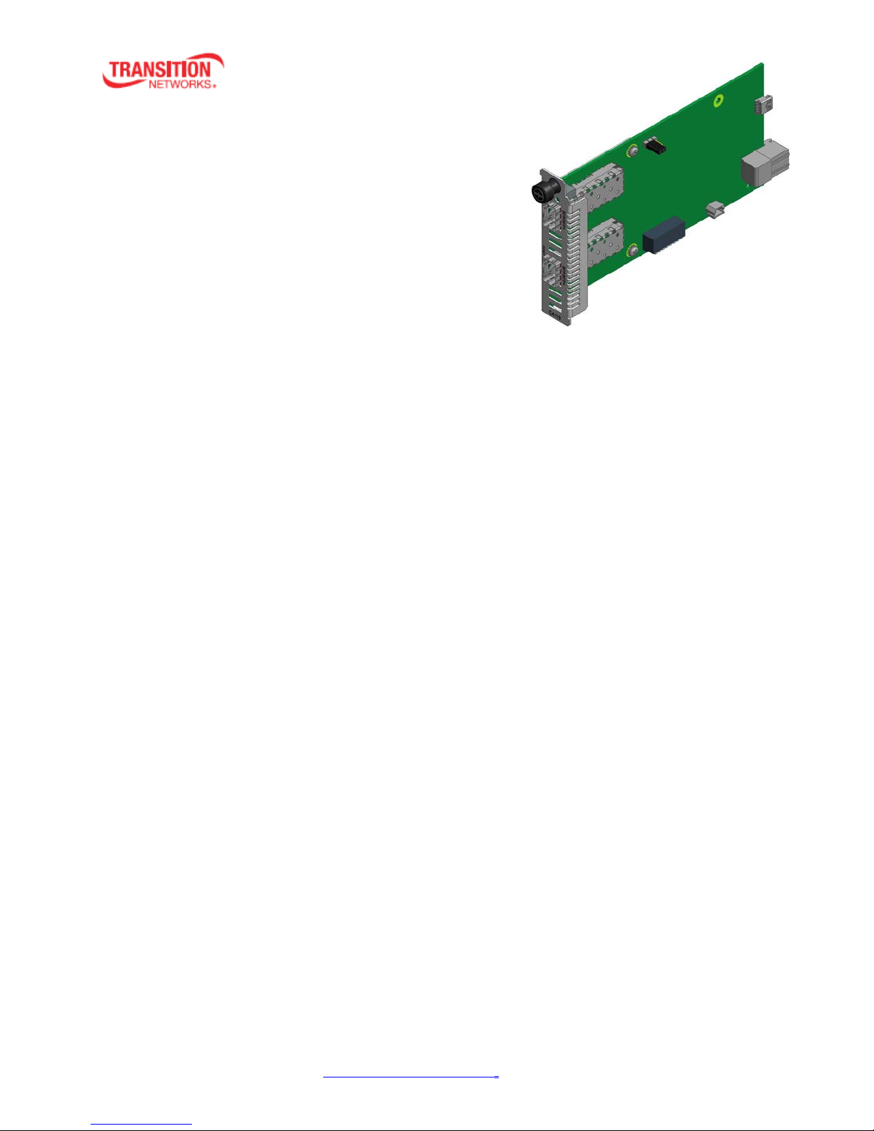
Transition Networks’ two-port C4110 series 10 Gbps Fiber-to-F i ber Conv er ter is des igned to ins ta ll in an
ION chassis. The ION x4110 is a 10 Gbps fiber-to-fiber port converter with two SFP+ slots that performs
full 3R (re-amplify, re-shape, and re-timing) signal regeneration. It can be used all alone or it can be
connected to another x4110, providing fiber-to-fiber conversion in the following user networks:
• 10G LAN, 10G WAN
• 10G Fiber Channel
• SONET OC192
• 10G OTN (G.709)
The C4110 can be used in telecom and enterprise applications where 10 Gbps links require fiber
extension or where 10 Gbps links require an interface between two different types of fiber. The C4110
performs a wide variety of protocol transparent service; it supports virtually any protocol from 1 Gbps to
11.5 Gbps:
• 10G LAN (10.3125 Gbps) / WAN (9.95 Gbps)
• SONET OC-192/SDH ST M-64 at 9.95 Gbps
• 10G Fiber Channel at 10.52 Gbps
• 1/2/4/8 Gbps Fiber channel
• OTU2 at 10.709 Gbps
• OTU1e at 11.05 Gbps
• OTU1f at 11.27 Gbps
• OTU2e at 11.09 Gbps
• OTU2f at 11.32 Gbps
• SONET OC-48/SDH ST M-16 at 2.40 Gbps
• Legacy 1G Ethernet at 1.25 Gbps
• Any other rate in the range of 1 - 11.5 Gbps
Models
The C4110 is an ION chassis slide-in-card (SIC). The S4110 is an ION Stand-alone device.
The S4110 is used as a stand-alone device or as a remote device when linked back to a managed
chassis card.
The C4110 SIC card can be managed by ION Web, ION CLI, or Focal Point 3.0. The S4110 can not be
remotely managed.
Manageable C4110 features are available when used in an ION Platform chassis along with an ION
Management Module (IONMM). The x4110 is delivered with a default configuration. You can change the
configuration via the ION Web interface, Focal Point 3.0, and the ION CLI.
Model
Note that the C4110 (ION Chassis Card) can be upgraded from the IONMM. The S4110 (Standalone
model) can not be upgraded from the IONMM.
Rates
33572 Rev. B https://www.transition.com/ Page 3 of 33
Page 4

Transitio n Networks C4110 Install Guide
Model
Description
SFP Modules
SFP and SFP+ modules supported. See the TN SF P webpage.
Accessories (ordered separately)
Document Overview
The purpose of this manual is to provide the information needed to install the S4110 to the point of
operation. Note that there is a separate install guide for the S4110.
Related Manuals and Online Help
A printed documentation card is shipped with each x4110 device. A substantial set of technical
documents, white papers, case studies, etc. are available on the Transition Networks web site at
https://www.transition.com
Transition Networks is not responsible. Other ION system and related device manuals are listed below.
1. Product Documentation Po st car d, 33504
2. ION C4110 Install Guide, 33572 (this manual)
3. ION S4110 Install Guide , 33573
4. ION x4110 Web User Guide, 33574
5. ION x4110 CLI Referenc e, 33575
6. Focal Point
7. ION Management Module (IONMM) Install Guide, 33420 and User Guide, 33457
8. ION System NID User Guides (33432, 33457, 33472, 33493, 33494, 33495, 33496)
9. Release Notes (firmware version specific)
™
. Note that this manual provides links to third party web sites for which
3.0 Management Application User Guide, 33293
Note: Information in this document is subject to change without notice. All information was deemed
accurate and complete at the time of publication. This manual documents the latest software/firmware
version. While all screen examples may not display the latest version number, all of the descriptions and
procedures reflect the latest software/firmware version, noted in the Record of Revisions on page 33.
33572 Rev. B https://www.transition.com/ Page 4 of 33
Page 5
Transitio n Networks C4110 Install Guide
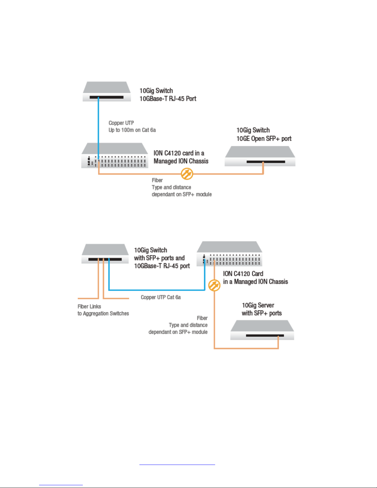
Application Examples
The figures below show switch-to-switch and switch-to-server appliaction examples.
Figure 1: 10Gig Switch to Switch
33572 Rev. B https://www.transition.com/ Page 5 of 33
Figure 2: 10Gig Switch to Server
Page 6
Transitio n Networks C4110 Install Guide
ION Chassis
S4110-4848
1 2
Customer Network
C4110
Customer Network
Port
2 1
S4110
Port
2 1
S4110
Port
2 1
Customer Network Customer Network
S4110
Port
2 1
Customer Network
Customer Network
ION Chassis
1 2
Customer Network
C4110-4848
Customer Network
Scenario. A
Scenario. B
ION Chassis
S4120-1048
1 2
C4110
10G Ethernet
Port
2 1
Scenario. F
Port.1: RJ45
Port.2: SFP+
10G Ethernet
Port.1: SFP+
Port.2: SFP+
Port.1: SFP+
Port.2: SFP+
Port.1: SFP+
Port.2: SFP+
Port.1: SFP+
Port.2: SFP+
Port.1: SFP+
Port.2: SFP+
Scenario. D
Scenario. E
Customer Network
Customer Network
Scenario. C
ION Chassis
1 2
C4110
1 2
C4110
ION Chassis
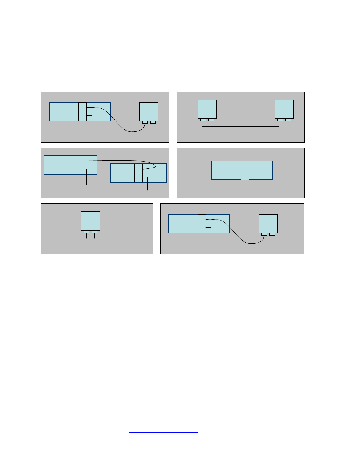
Network Scenarios
The C4110 provides up to 10Gig fiber-to-fiber port repeating and performs 3R (re-amplify, reshape) signal
regeneration. The figures below show how x4110 devices can be used in pairs (scenarios A,B,C below)
or used as single repeater in a customer network (scenarios D & E below); It can also interconnect with
an x4110-1048 (scenario F).
Figure 3: Network Scenarios
33572 Rev. B https://www.transition.com/ Page 6 of 33
Page 7

Transitio n Networks C4110 Install Guide
Pre-Installation
Safety
Before installing the C4110, read the “Electrical Safety Warnings” on page 32 of this manual and ensure
that the requirements noted are met. During installation and maintenance, avoid direct exposure to laser
beams. Specifically, do not look into laser ports. Ensure that each SFP/SFP+ port at which laser beams
are (or will be) present is occupied by an SFP/SFP+ that is locked in position. See the related SFP/SFP+
manual for details. See "Electrical Safety Warnings" on page 32 for Electrical Safety Warnings translated
into multiple languages.
Unpacking
1. Carefully unpack all C4110 contents.
2. Verify receipt of all C4110 components; see “Ship Kit Contents” below.
3. Place the C4110 and related materials in the desired install location.
4. Save the C4110 shipping carton and packing materials for future use.
Ship Kit Contents
The C4110 is shipped with some standard and some optional components. Make sure you have received
the following standard items:
One C4110 device
One printed Product Documentation postcard
CAUTION: Wear a grounding device and observe electrostatic discharge precautions when handling the
C4110. Failure to observe this caution could result in damage or failure of the C4110.
33572 Rev. B https://www.transition.com/ Page 7 of 33
Page 8
Transitio n Networks C4110 Install Guide
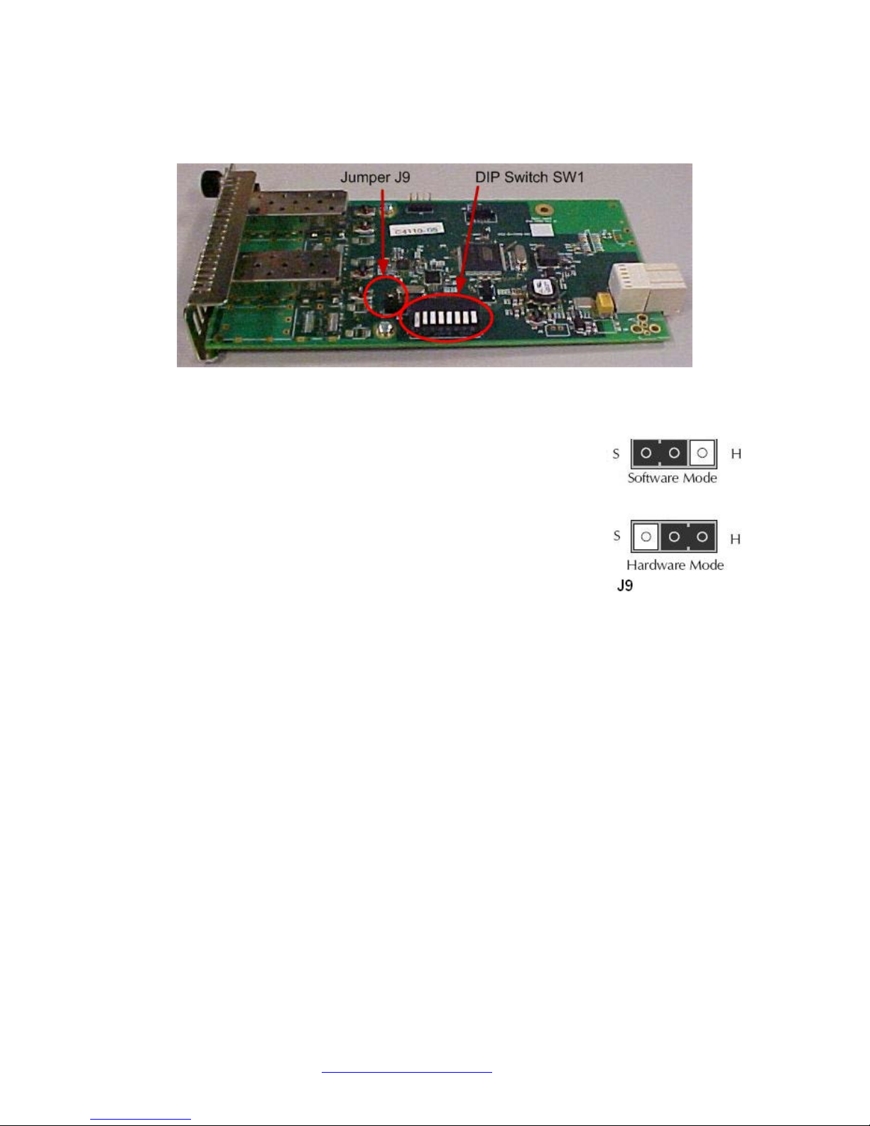
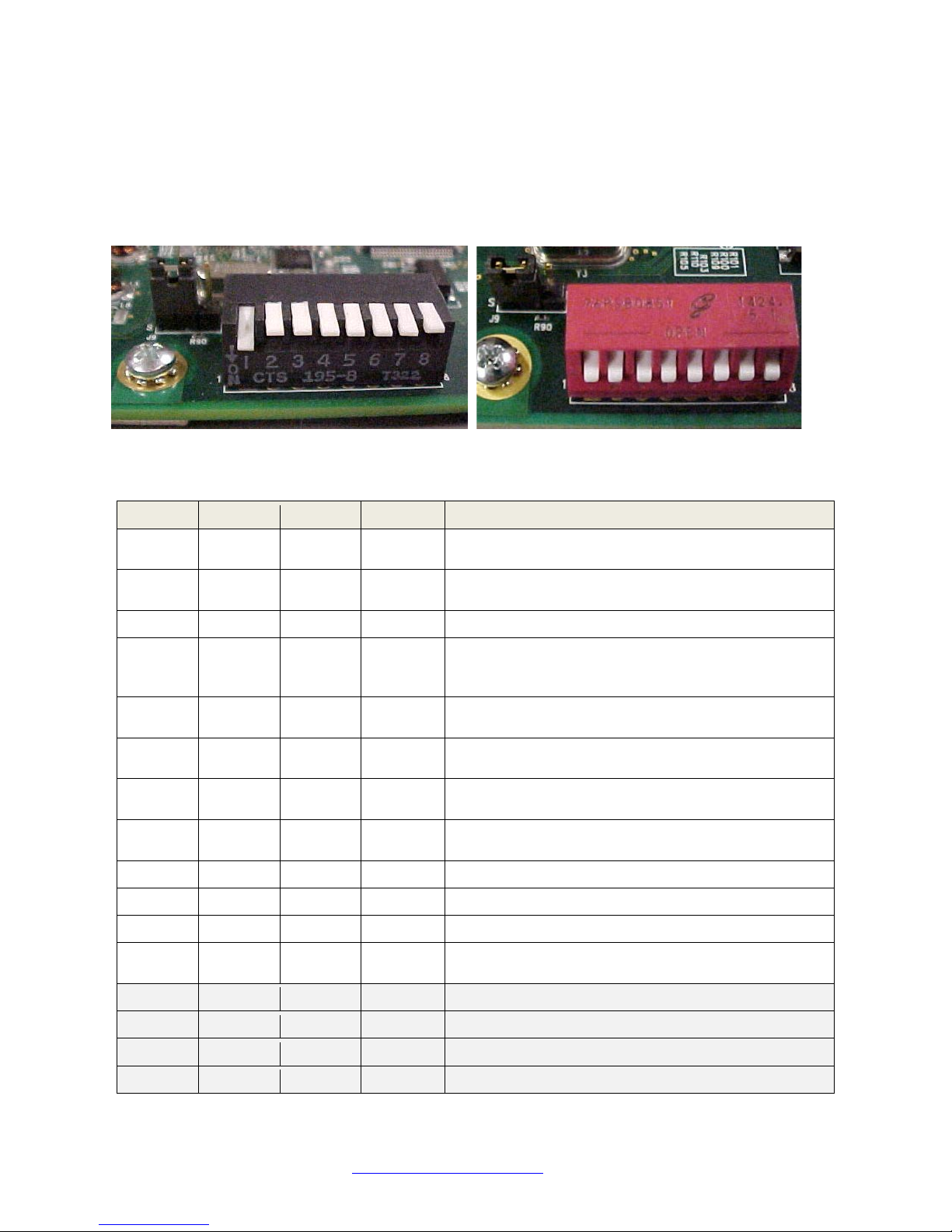
DIP Switch (SW1) and Jumper (J9)
The C4110 has a field-configurable DIP Switch (SW1) and Jumper (J9) as shown below.
Figure 4. Jumper J9 and DIP Switch SW1
Hardware/Software Mode Jumper (J9)
The hardware/software 3-pin header, J9, is located on the circuit board
(labeled S and H). Use a small needle-nose pliers to set the jumper.
S - Software In this position, the mode of the C4110 is deter mined by the
most-recently saved software settings. This is the default
setting.
H - Hardware In this position, the mode of the C4110 is deter mined by the
8-position DIP switch (hardware) settings.
Note: you must change the J9 setting to H (Hardware mode) to be able to use the DIP Switch settings
(see below).
Use the CLI command “
From the web GUI, navigate to the ION Stack > Chassis > C4110 menu path and check the MAIN tab’s
System Configuration section > Configuration Mode field setting (i.e., hardware or software).
show card info” to show the current Config mode setting (hardware or software).
33572 Rev. B https://www.transition.com/ Page 8 of 33
Page 9
Transitio n Networks C4110 Install Guide
1 2 3 4 Data Rate
10GE = 10 gigabit Ethernet (also 10GbE or 10 GigE).
This is the factory default setting.
10GFC + FEC = 10GbE Fibre Channel with Forward
Error Correction).
Down
Up
Down
Down
10GFC = 10GbE Fibre Channel.
WAN/OC-192+FEC = OC-192 network line with
Forward Error Correction).
WAN/OC-192 = OC-192 network line with
transmission speeds up to 9953.28 Mbit/s.
8GFC = 8G Fiber Channel with 8.5 gigabaud Line
rate and 1,600 MBps Throughput (at full duplex).
4GFC = 4G Fiber Channel with 4.25 gigabaud Line
rate and 800 MBps Throughput (at full duplex).
2GFC = 2G Fiber Channel with 2.125 gigabaud Line
rate and 400 MBps Throughput (at full duplex).
Up
Down
Down
Up
2.5GE = 2.5 gigabit Ethernet.
Down
Up
Down
Up
1GE = 1 gigabit Ether net.
OC-48 = network line with transmission speeds of up
to 2488.32 Mbit/s.
Down
Down
Up
Up
Reserved (Default).
Up
Down
Up
Up
Reserved (Default).
Down
Up
Up
Up
Reserved (Default).
DIP Switch SW1 (Function Settings in Hardware Mode)
The 8-position DIP switch labeled SW1 is on the bottom edge of the C4110 PCB. The factory default
setting is SW1 – 4 in the Down position (all Down). SW5 - 8 settings are not used (‘do not care’).
Note 1: you must change the J9 setting to ‘Hardware’ mode to be able to use the DIP Switch settings
(see above). Remove the DIP switch protective tape covering the switches. Use a small, flat-blade
screwdriver (or similar tool) to set the switches to site requirements.
Note 2: Component labeling may vary; the figure above left shows SW 1 in the position labeled ‘ON’
(Down), and SW 2-8 are shown in the ‘Off’ or ‘Up’ position. The figure above right shows all 8 switches in
the Closed (down) position (opposite from the position labeled “OPEN).
Down Down Down Down
Up Down Down Down
Up Up Down Down
Down Down Up Down
Up Down Up Down
Down Up Up Down
Up Up Up Down
Down Down Down Up 1GFC = 1GbE Fibre Channel.
Up Up Down Up
transmission speeds up to 9953.28 Mbit/s with
Up Up Up Up Reserved (Default).
33572 Rev. B https://www.transition.com/ Page 9 of 33
Page 10
Transitio n Networks C4110 Install Guide
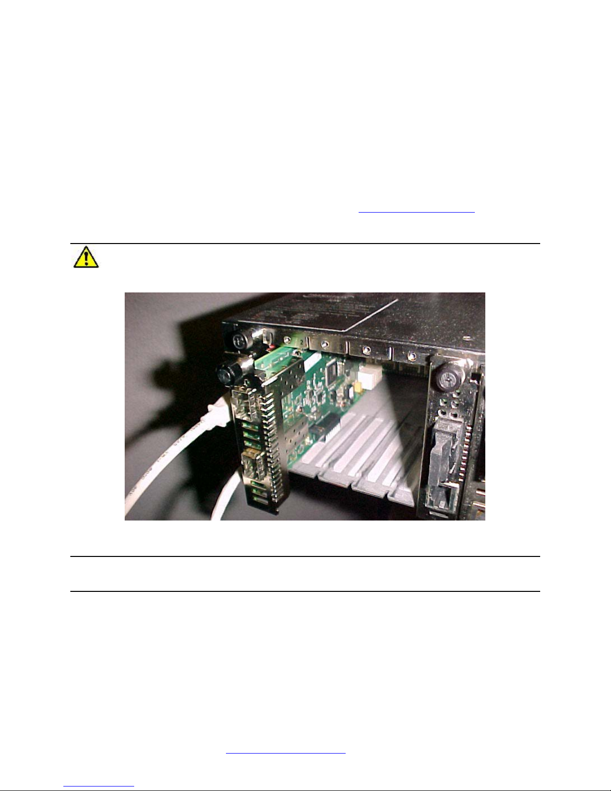
Installation and Setup
General
This section describes how to install the C4110 and the procedures to access and initially set it up via
either a local serial interface (USB) or a remote Ethernet connection (Telnet session or Web interface).
Install the C4110 in the ION Chas sis
The C4110 is a slide-in module that can only be installed in a Transition Networks ION chassis (ION106-x
or ION219-x). For a complete list of ION platform products, go to https://www.transition.com
The following describes how to install the C4110 in the ION chassis.
Caution: Failure to wear a grounding device and observe electrostatic discharge precautions
when installing the C4110 could result in damage or failure of the module.
.
IMPORTANT
The C4110 slide-in cards are “hot swappable” devices, and can be installed with chassis power on.
1. Locate an empty slot in the ION System chassis. If necessary, remove a chassis slot cover from the
ION Chassis (keep the slot cover and screw).
2. Grasp the edges of the C4110 by its front panel, align the card with the upper and lower slot guides,
and carefully insert the C4110 into the slot.
3. Firmly seat the C4110 against the chassis back panel.
4. Push in and rotate clockwise the panel fastener screw to secure the C4110 to the chassis (Figure 5).
5. Note that the card’s Power LED lights. See Accessing the C4110 on page 15.
33572 Rev. B https://www.transition.com/ Page 10 of 33
Figure 5: Chassis Installation
Page 11

Transitio n Networks C4110 Install Guide
Port Locations
The C4110 has two ports. The locations of PORT1 and PORT 2 (SFP/SFP+) are shown below.
Figure 6: Port Locations
Installing SFP/SFP+ Devices
The C4110 lets you install SFP/SFP+ devices of choice to make a fiber connection. The C4110 has two
SFP/SFP+ ports.
Note: The S4100 is an “any rate to same rate” device, meaning the two SFPs used must both support the
same data rate. However, two SFPs can support different types of fiber and different transmission
distances.
33572 Rev. B https://www.transition.com/ Page 11 of 33
Figure 7: SFP/SFP+ Installation
Page 12

Transitio n Networks C4110 Install Guide
SFP/SFP+ Optical Transceivers
Transition Networks SFP and SFP+ devices are small form factor, hot-pluggable transceivers which allow
for a single piece of network equipment to be connected to a multitude of interfaces, protocols, and
transmission media via the SFP/ SFP+ port. All of Transition’s SFPs and SFP+ devices are compliant with
the Multi-Sourcing Agreement (MSA) ensuring interop er abi lit y with all other MS A c om pliant networking
devices. The SFP/SFP+ module used defines the fiber length and type that can be used. Identical
SFP/SFP+ modules must be used at each end for a given port. (One port in LAN mode with the other port
is in WAN mode is not a valid scenario.) Note that SFP+ power is Level II - 1.5W (1.5W is the maximum
per MSA).
To install an SFP/SFP+ device in the C4110:
1. Position the SFP/SFP+ device at either installation slot, with the label facing up.
2. Carefully slide the SFP/SFP+ device into the slot, aligning it with the internal installation guides.
3. Ensure that the SFP/SFP+ device is firmly seated against the internal mating connector.
4. Connect the fiber cable to the fiber port connector of the SFP/SFP+ device.
See the TN SFP webpage
for the latest SFP information.
Cabling
The C4110 can be used in telecom and enterprise applications w here 1Gig to 10Gig links require fiber
extension or where 1Gig to 10Gig links require an interface between two fiber networks. It performs 3R
(re-amplify, re-shape, and re-time) signal regeneration. The C4110 is protocol ‘agnostic’, supporting a
wide variety of protocols in a network; from 1 to 11.5Gbps, including:
• 10G LAN,10G WAN
• 10G Fiber Channel
• SONET OC192
• 10G OTN (G.709)
The figure above shows cabling a C4110 to an S4110. The procedure is provided belo w.
33572 Rev. B https://www.transition.com/ Page 12 of 33
Figure 8: C4110-to-S4110 Connection
Page 13

Transitio n Networks C4110 Install Guide
Install Fiber Cable
Port 1 and 2: Fiber Ports
1. Locate a fiber cable with male, two-stranded TX to RX connectors installed at both ends. See “Cable
Specifications” on page 26 for details.
2. Connect the fiber cable to the 10GE SFP+ fiber port (Port 2 labeled 10GE SFP+) on the C4110 as
described:
• Connect the male TX cable connector to the female TX connector.
• Connect the male RX cable connector to the female RX connector.
3. Connect the fiber cables to the 10GE fiber port on the other device (another media converter, hub,
S4110, etc.) as described:
• Connect the male TX cable connector to the female RX connector.
• Connect the male RX cable connector to the female TX connector.
Figure 9: SFP+ Installation
Focal Point™ Installation
For Focal Point™ 3.0 Management Application installation information, see the Focal Point User Guide,
33293.
IONMM Installation
For IONMM Management Module installation information, see the IONMM Ins tal l Guide , 33420.
For IONMM operation see the ION Management Module (IONMM) User Guide, 33457.
33572 Rev. B https://www.transition.com/ Page 13 of 33
Page 14

Transitio n Networks C4110 Install Guide
Operation
Power and Fiber Status LEDs
The status LEDs (labeled PWR and LINK SFP+) are located next to the fiber port (Port 2). Use the status
LEDs to monitor C4110 operation in the network.
LED Label Meaning Operation
PWR
Power Green ON for power applied to board.
PORT 1
LINK
PORT 2
LINK
SDF Fiber Status 1
On = Fiber Signal Detected.
Off = Fiber Signal Not Detected.
On = Fiber Signal Detected.
SDF Fiber Status 2
Off = Fiber Signal Not Detected.
33572 Rev. B https://www.transition.com/ Page 14 of 33
Figure 10: Power and Fiber Status LEDs
Page 15

Transitio n Networks C4110 Install Guide
Accessing the C4110
The C4110 can be accessed through an Ethernet network connection on the IONMM installed in the ION
chassis along with the C4110. The network connection can be done via a Telnet session or a Web
graphical user interface (GUI).
Installing the USB Driver (Windows XP)
IMPORTANT
The following driver installation instructions are for the Windows XP operating system only. Installing
the USB driver using another operating system is similar, but not necessarily identical to the following
procedure.
To install the USB driver on a computer running Windows XP, do the following.
1. Extract the driver from the TN website
You must log in or create an account to download firmware. For further assistance see the “Contact
Us” section.
2. Connect the C4110 to the USB port on the PC.
Note: for slide-in modules installed in an ION Chassis, the USB connection will be made to the ION
Management Module (IONMM) if one is installed in the ION chassis.
The Welcome to the Found New Hardware Wizard window displays.
3. Select No, not this time.
4. Click Next.
The installation options window displays.
5. Select Install from a list or specific location (Advanced).
6. Click Next.
The driver search installation options window displays.
7. Click Browse.
8. Locate and select the USB driver downloaded in step 1 above.
9. Click Next. Driver installation begins.
and place it in an accessible folder on the local drive of the PC.
10. When the finished installing screen displays, click Finish. The USB driver installation is complete.
You must now configure access the C4110 via an Ethernet network.
33572 Rev. B https://www.transition.com/ Page 15 of 33
Page 16

Transitio n Networks C4110 Install Guide
Installing the USB Driver (Windows 8)
IMPORTANT
The following driver installation instructions are for the Windows 8 operating system only. Installing the
USB driver using another operating system is similar, but not necessarily identical to this procedure.
To install the USB driver on a computer with the Windows 8 operating system, do the following.
1. Extract the driver from the Produc t Su ppor t
local drive of the PC.
2. Connect the IONMM to the USB port on th e PC.
3. Press the Windows key and type “startup”. Choose “Change advanced startup options”.
4. On the right side click on the “Restart now” button under Advanced startup.
5. Your PC will reboot and display the “Choose an Option” screen; choose “Troubleshoot”.
webpage and place it in an accessible folder on the
33572 Rev. B https://www.transition.com/ Page 16 of 33
Page 17

Transitio n Networks C4110 Install Guide
6. At the Troubleshoot screen choose “Advanced options”.
7. In the Advanced options screen choose “Startup Settings”.
8. A list of Windows Startu Settings displays; click the “Restart” button. Your PC will reboot.
33572 Rev. B https://www.transition.com/ Page 17 of 33
Page 18

Transitio n Networks C4110 Install Guide
9. Your PC will boot into a Startup Settings screen. Select “7) Disable driver signature enforcement”.
10. Your PC will reboot one more time and will not load normally.
11. Plug the USB into the PC and IONMM card and have the USB driver saved locally to the PC.
12. The install will fail again; right click on “My computer” and click “Manage” to get to “Device
Manager”.
13. In Device Manager, expand “Ports (COM& LPT)” to view your connection with an error on the
driver.
14. Right click on the driver and choose “Update driver software”.
15. You will get a pop up with two options; choose “Browse my PC for driver”.
16. Point to the folder location where you have the driver installed and click “install”.
17. You will receive another Windows Security pop up; choose “Install this driver software anyway”.
18. The driver will ins tall correctly and you will no longer see the error on the connection in Device
Manager.
19. You will now be able to connect via USB to the device and log in. On a stand-alone device, be sure
to set it to “Remote” so you can remotely manage the device.
33572 Rev. B https://www.transition.com/ Page 18 of 33
Page 19

Transitio n Networks C4110 Install Guide
Access via an Ethernet Network
The C4110can be managed remotely through the Ethernet network via either a Telnet session or the Web
interface. Before this is possible, you must set up the IP configuration for the C4110.
IMPORTANT
It is recommended that you initially set up the IP configuration through the serial interface (USB
connection). See “Accessing the C4110” on page 15.
Otherwise, in order to communicate with the C4110across the network for the first time, you must
change the network settings (IP address, subnet mask and default gateway address) of your PC to
coincide with the defaults of the C4110 (see “Defaults” on page 25
for the PC as you will need to reset them after setting the IP configuration for the C4110.
). Make note of the original settings
Starting a Telnet Session
The C4110 can be controlled from a remote management station via a Telnet session over an Ethernet
connection. The C4110 is controlled and configured through CLI commands. Use the following procedure
to connect to and access the C4110 via a Telnet session.
1. Click Start.
2. Select All Programs > Accessories.
3. Click Command Prompt. The command prompt window displays.
4. At the command line type: telnet <xx> where:
xx = IP address of the C4110 (e.g., 192.168.1.10)
5. Press Enter. The login prompt displays.
Note: If your systems uses a security protocol (e.g., RADIUS, SSH, etc.), enter the login and password
required by that protocol.
6. Type your login (the default is ION). Note: the login is case sensitive.
7. Press Enter. The password prompt displays.
8. Type your password (the default is private). Note: the password is case sensitive.
33572 Rev. B https://www.transition.com/ Page 19 of 33
Page 20

Transitio n Networks C4110 Install Guide
9. Press Enter. The command line prompt displays.
10. Enter a go command to change the location for the command prompt. The go command format is:
go [c=<0-16>] [s=<0-32>] [l1ap=<1-15>] [l2ap=<1-15>] (l1p=<1-5>|l2p=<1-15>|l3p=<115>|l1d|l2d|l3d)
11. Enter commands to set up the various configurations for the C4110. For web GUI configuration, see
the x4110 Web User Guide. For CLI command descriptions see the x4110 CLI Reference manual.
Note: If required by your organization’s security policies and procedures, use the CLI command set
community write=<xx> to change the default password. See the x4110 C LI Refe r ence manual.
Terminating a Telnet Session
To terminate the Telnet session:
1. Type q(uit).
2. Press the Enter key.
Web Browsers Supported
The ION system supports the latest vresion of most popular web browsers (e.g., Firefox (Mozilla Firefox),
Internet Explorer, Google Chrome, Opera).
33572 Rev. B https://www.transition.com/ Page 20 of 33
Page 21

Transitio n Networks C4110 Install Guide
Starting the Web Interface
The C4110 can be controlled and configured from a remote management station via a Web graphical
user interface (GUI) over an Ethernet connection. Information is entered into fields on the various screens
of the interface. Note: fields that have a grey background can not be modified.
A Web session can be used to connect to and set up the C4110.
IMPORTANT
• Do not use the browser’s back button to navigate the screens. This causes the connection to
drop.
• Do not use the keyboard’s back space key in grayed out fields. This causes the connection to
drop.
• For DHCP operations, a DHCP server must be on the network and available.
To sign in to the C4110 via the Web:
1. Open a web browser.
2. In the address (URL) block, type the IP address of the IONMM (the default address is 192.168.1.10).
3. Click Go or press Enter. The ION System sign in screen displays.
Note: If your systems uses a security protocol (e.g., RADIUS, SSH, etc.), you must enter the login and
password required by that protocol.
1. Type the System name (the default is ION). Note: the System name is case sensitive - all upper
case.
2. Type the password (the default is private). Note: the password is case sensitive - all lower case.
33572 Rev. B https://www.transition.com/ Page 21 of 33
Page 22

Transitio n Networks C4110 Install Guide
3. Click Sign in or press Enter. The opening screen displays.
4. Click the plus sign [+] next to ION Stack. This unfolds "ION Stack" node in the left tree view and will
refresh device status.
5. Click the plus sign [+] next to Chassis to unfold the chassis devices.
6. Select the appropriate C4110-4848 device. The MAIN screen displays for the selected C4110.
7. You can use the various fields to configure the device and ports. For web GUI configuration, see the
x4110 Web User Guide.
Note: If required, use the set community CLI command to change the default password according to
your organization’s security policies and procedures.
33572 Rev. B https://www.transition.com/ Page 22 of 33
Page 23

Transitio n Networks C4110 Install Guide
Terminating the Web Interface
To sign out from the Web interface, in the upper left corner of the ION System Web Interface:
1. Click the System dropdown.
2. Click Sign out.
The ION sign- in screen displays.
Note: The C4110 does not automatically log out upon exit or after a timeout period, which could leave it
vulnerable if left unattended. Follow your organizational policy on when to sign out from the ION System
via the Web Interface
33572 Rev. B https://www.transition.com/ Page 23 of 33
Page 24

Transitio n Networks C4110 Install Guide
Local
Media
Converter
Remote
Media
Converter
①
②
④ ③
Near-End
Device
Far-End
Device
Original fault on the Port-1
Local converter turns off the
fiber transmit on port-2
remote converter
disables its Port-1
This direction of link still
valid
#1
#2-Tx #2-Rx
#1
#2-Rx #2-Tx
DMI connector type: e.g., LC
DMI temperature: 107.6*F
DMI temperature alarm: normal
DMI Receive power intrusion threshold: 0*uW
Product Features
The features described and illustrated in this section include Link Pass through and Digital Monitoring
Interface (DMI).
Link Pass Through (LPT)
This function causes loss of link on one side of a media converter to be passed through to the other side,
so that upstream equipment can see fault conditions that would otherwise be hidden by the media
converters.
The LPT feature allows the Device to monitor the Fiber RX (receive) ports for loss of signal. For example,
when the Fiber #1link on the near end device is lost (1), the local Device turns off the fiber transmit on
Fiber #2 (2), thus, “passing through” the link loss. The remote Device disables the Fiber #1 link to the farend device (3), which prevents the loss of valuable data unknowingly transmitted over an invalid link.
Note that although the link from local fiber #2-Tx to remote #2-Rx is disabled, the link from remote #2-Tx
to local #2-Rx is still alive(4). The LPT process is illustrated in the figure below.
Figure 11: Link Pass Through (LPT)
Digital Monitoring Interface (DMI)
The Diagnostic Monitoring Interface (DMI) feature allows diagnosing problems within the network.
The DMI function displays C4110 diagnostic / maintenance information such as 10Gbps fiber interface
characteristics, diagnostic monitoring parameters, and supported fiber media lengths. All DMI events will
trigger notification. Intrusion detection, based on Rx Power level, is available for triggering any drop in the
Rx power.
Within each function, the DMI device will send a trap whenever a high or low warning event or high or low
alarm event occurs (for a total of 16 traps). If both the local and remote NIDs are DMI models, the DMI
device will indicate whether the trap event is from a local or remote device.
C4110 Diagnostic Monitoring Interface information includes:
DMI ID: e.g., SFP
DMI Nominal bit rate: e.g., 10500*Mbps
DMI 9/125u Singlemode Fiber (m): N/A
DMI 50/125u Multimode Fiber (m): 80*m
DMI 62.5/125u Multimode Fiber (m): 3*10m
Copper(m): N/A
DMI fiber interface wavelength: 850*nm
DMI temperature: 42.0*C
DMI transmit bias current: 6240*uA
DMI transmit bais alarm: normal
DMI Transmit power: 589*uW
DMI Transmit power: -2.299*dBM
DMI Transmit power alarm: normal
DMI Receive power: 573*uW
DMI Receive power: -2.418*dBM
DMI Receive power alarm : normal
Vendor Specific Information (Vendor Name, Vendor Part Number, Serial Number, Revision, MFG Date
Code, Transceiver Type, and Vendor OUI) is available with firmware v 1.2.6 and above.
33572 Rev. B https://www.transition.com/ Page 24 of 33
Page 25

Transitio n Networks C4110 Install Guide
Technical Specifications
Standards: IEEE802.3ae / ITU.G.709 / SFF843 1
Data Rate 10 Gbps
Dimensions Width: 0.86” [21.85 mm]
Depth: 6.5” [165 mm]
Height: 3.4” [86.36 mm]
Power Source 12VDC from ION backplane
Power Consumption 4.2W (350mA @12V)
Environment See ION chassis specifications
Operating Temperature 0 to 50 degrees C
Storage Temperature -40 to 85 degrees C
Altitude 0-10,000 feet
Operating Humidity 5% to 95% (non-condensing)
Shipping Weight 1 lb. (0.45 Kg.)
MTBF Greater than 250,000 hours (MIL-HDBK-217F)
Greater than 687,000 hours (Bellcore)
Regulatory Compliance for:
Emission FCC Class A; EN55022 Class A
Immunity EN55024
Safety Compliance CE Mark
Warranty: Lifetime
Max. Frame Size: 16384 bytes jumbo frame support
The information in this user’s guide is subject to change. For the latest information, see the online user’s
guide at: https://www.transition.com
.
WARNING: Visible and invisible laser radiation when open. DO NOT stare into the beam or view the
beam directly with optical instruments. Failure to observe this warning could result in an eye injury or
blindness.
WARNING: Use of controls, adjustments or the performance of procedures other than those specified
herein may result in hazardous radiation exposure.
Defaults
After you configure the C4110 and insert it into ION chassis, it will start up and run automatically using its
defaults. The C4110 initialization default values are shown below.
Parameter Default Value Property
Configuration Mode Software (SW) mode Read only
Device Description (blank) Read & Write
Data Rate Retiming 10GE Read & Write
Fiber Port
Link Status Down Read only
You can change the default configuration via the ION Web GUI, the ION CLI (Command Line Interface),
or via Focal Point 3.0.
33572 Rev. B https://www.transition.com/ Page 25 of 33
Page 26

Transitio n Networks C4110 Install Guide
Cable Specificati ons
The physical characteristics must meet or exceed IEEE 802.3™ specifications.
Fiber port: SFP+, both Class-I and Class-II, 10.3125Gbps.
Cable Types
The cabling specifications are provided for reference and troublesho oti ng pur pos es .
Fiber (10GbE) Cabling
The two general types of fiber optic cables are SMF (single-mode fiber) and MMF (multi-mode fiber).
SMF has an optical core of approximately 9 μm (microns), and has lower modal dispersion than MMF,
and can support distances of at least 10 Km and as high as 80-100 Km (Kilometers) or more, depending
on transmission speed, transceivers, etc..
MMF has an optical core of either 50 μm or 62.5 μm, and it supports distances up to 600 meters,
depending on transmission speeds and transceivers.
Fiber Cable Descriptions
Standard Cable Type
OM1 Multi-mode (MMF) 62.5/125 μm 33 meters (SR) 850 / 1300 nm
OM2 Multi-mode (MMF) 50/125 μm 82 meters (SR) 850 / 1300 nm
OM3 Multi-mode (MMF) 50/125 μm 300 meters (SR) 850 / 1300 nm
OM4 Multi-mode (MMF) 50/125 μm 550 meters (SR) 850 / 1300 nm
OS1 Single mode (SMF) 9 μm up to 10,000m 1310 / 1550 nm
Core
Diameter
IEEE Standard
Distance
Wavelength
OS1 SMF optics are used for distances up to 10,000m (6.2 miles) with standard transceivers and can
work at longer distances with special transceivers and switching infrastructure.
The C4110 supports:
10GBase-SR: The most common type of fiber-optic 10GbE cable that supports an SFP+ connector with
an optical transceiver rated for 10Gb transmission speed (also known as “short reach” fiber-optic cables).
10GBase-LR: The the “long reach” fiber optic cables that support single-mode fiber optic cables and
connectors. Provides serialized data at a line rate of 10.3125 Gbit/s.10GBASE-LR has a specified reach
of 10 kilometres (6.2 mi), but 10GBASE-LR optical modules can often manage distances of up to 25
kilometres (16 mi) with no data loss.
10GBase-ER: The "extended reach" port type for single-mode fiber that uses 1550 nm lasers. Its Physical
Coding Sublayer 64b/66b PCS is defined in IEEE 802.3 Clause 49 and its Physical Medium Dependent
PMD in Clause 52. It delivers serialized data at a line rate of 10.3125 Gbit/s.
10GBase-ZR: An 80 km (50 mile) range ER pluggable interface, the 80 km PHY is not specified within
the IEEE 802.3ae standard, and manufacturers have created their own specifications based on the 80 km
PHY described in the OC-192/STM-64 SDH/SONET specifications.
Note: the interface standard used is defined by the fiber module used and is transparent to the x4110.
All other standards are limiting mode (EDC disabled).
Note: the C4110 does not support 10GBase-LX4, 10GBase-CX4, or 10GBase-LRM.
33572 Rev. B https://www.transition.com/ Page 26 of 33
Page 27

Transitio n Networks C4110 Install Guide
Optical Transport Network (OTN)
The Optical Transport Hierarchy (OTH) is a new transport technology for the Optical Transport Network
(OTN) developed by the ITU. OTH is based on the network architecture defined in ITU G.872
"Architecture for the Optical Transport Network (OTN)".
G.872 defines an architecture that is composed of the Optical Channel (OCh), Optical Multiplex Section
(OMS) and Optical Transmission Section (OTS). G.872then describes the functionality that needed to
make OTN work.
Compared to SONET/SDH, using OTN offers advantages (stronger Forward Error Correction, more levels
of TCM, transparent transport of Client signals, switching scalability) and disadvantages (requires new
hardware and management system).
OTU Typ e OTU Bit Rate (Nominal)
OTU1 255/238 x 2 488 320 kbit/s
OTU2 255/237 x 9 953 280 kbit/s
OTU3 255/236 x 39 813 120 kbit/s
The OTU bit rate tolerance is ±20 ppm for OTU1, OTU2, and OTU3. The nominal OTUk rates are
approximately 2 666 057.143 kbit/s (OTU1), 10 709 225.316 kbit/s (OTU2) and 43 018 413.559 kbit/s
(OTU3).
See http://www.itu.int/rec/T-REC-G.709/
for more information.
Fibre Channel (FC)
FC (Fibre Channel) is a high-speed network technology (common rates of 2-, 4-, 8- and 10-Gbps) often
used to connect computer data storage. Fibre Channel is standardized in the T11 Technical Committee of
INCITS
committee.
Note: When FC technology was developed, it supported only optical cabling (fiber). Copper cable support
was later added, so the development committee kept the same name but changed to the British spelling
'fibre' for the standard. The American English spelling 'fiber' refers only to optical cabling, so a network
using 'fibre' can be implemented either with copper or optical cabling.
The FC protocol has a range of speeds based on a various underlying transport media. Native FC speed
variants include:
Fibre Channel does not follow OSI Layer modeling, but is similarly split into five layers (FC0 - FC4):
FC4: Protocol-mapping layer, in which application protocols, such as SCSI or IP, are encapsulated into a
PDU for delivery to FC2.
FC3: Common services layer, a thin layer that could eventually implement functions like encryption or
RAID redundancy algorithms.
(the International Committee for Information Technology Standards) an ANSI standards
Media Line-rate (GBps) Throughput (full duplex; Mbps)* Availability
1GFC 1.0625 200 1997
2GFC 2.125 400 2001
4GFC 4.25 800 2004
8GFC 8.5 1,600 2005
10GFC 10.52 2,550 2008
33572 Rev. B https://www.transition.com/ Page 27 of 33
Page 28

Transitio n Networks C4110 Install Guide
SONET (Synchronous Optical Transport Network)
Synchronous Optical Network, a standard for connecting fiber-optic transmission systems. SONET was
proposed by Bellcore in the middle 1980s and is now an ANSI standard.
SONET defines interface standards at the physical layer of the OSI seven-layer model. The standard
defines a hierarchy of interface rates that allow data streams at different rates to be multiplexed. SONET
establishes Optical Carrier (OC) levels from 51.8 Mbps (OC-1) to 9.95 Gbps (OC-192). The international
equivalent of SONET, standardized by the ITU, is called SDH.
SONET and Synchronous Digital Hierarchy (SDH) are standardized protocols that transfer multip le d i git a l
bit streams synchronously over optical fiber using lasers or highly coherent light from light-emitting diodes
(LEDs). At low transmission rates data can also be transferred via an electrical interface. The method was
developed to replace the Plesiochronous Digital Hierarchy (PDH) system for transporting large amounts
of telephone calls and data traffic over the same fiber without synchronization problems. SONET generic
criteria are detailed in Telcordia Technologies Generic Requirements document GR-253-CORE.
Both SDH and SONET are widely used today: SONET in the United States and Canada, and SDH in the
rest of the world. Although the SONET standards were developed before SDH, it is considered a variation
of SDH because of SDH's greater worldwide market share.
describe identical features or functions. This can cause confusion and exaggerate their differences. With
a few exceptions, SDH can be thought of as a superset of SONET.
SONET and SDH often use different terms to
Messages
Message: Setting values failed (snmp operation error, possible reasons: invalid data, error data
sequence, etc)
Meaning: The selected parameter setting was not recognized.
Recovery: Click the Refresh button to clear the error message.
Message: The DMI feature is not supported on current port.
Meaning: Either the port or the SFP does not support DMI, or an SFP is not currently installed in Port 1.
Recovery: Either inser t an SFP/ SF P + in Port 1, or change to Port 1, or change SFPs to a type that
supports DMI. See notes above for SFP DMI support.
33572 Rev. B https://www.transition.com/ Page 28 of 33
Page 29

Transitio n Networks C4110 Install Guide
Troubleshooting
If a problem or exception occurs, the C4110 will send related Trap message to the Trap Server to report
this event. You can launch the Trap Server in Focal Point 3.0 to capture the Trap message to better
understand C4110 status.
1. Is the PWR (power) LED lit?
NO
• Is the C4110 inserted properly into the ION chassis?
• Is the power cord properly installed in the ION chassis and in the grounded AC outlet?
• Does the grounded AC outlet provide power?
• Contact Tech Support. See “Contact Us” below.
YES
• Proceed to step 2.
2. Is the LINK LED lit?
NO
• Check that the SFP+ device is supported and properly connected. See “Installing SFP/SFP+
Devices” on page 11.
• Check the fiber cables for proper connection to the SFPs.
• Verify that the cable specs are met. See “Cable Specifications” on page 26.
• Contact Tech Support. See “Contact Us” below.
YES
• Proceed to step 3.
3. Is the CLI accessible?
NO
• Check the Install process. See “Installation and Setup” on page 10.
• Check the cabling. See “Install Fiber Cable” on page 13.
• Contact Tech Support. See “Contact Us” below.
YES
• Proceed to step 4.
4. Is the web GUI accessible?
NO
• Check the Install process. See “Installation and Setup” on page 10.
• Check the cabling. See “Cable Specifications” on page 26.
YES
5. Does the “Getting card version failed” display indicating that the C4110 card is not discovered by
the ION chassis.
• Make sure the HW / SW mode is set correctly. See “DIP Switch (SW1) and Jumper (J9)” on
page 8.
6. Does the Data Rate Retiming setting match the SFP SFP+ device being used ?
No
• Change the Data Rate Retiming setting or change the type of SFP/SFP+ device so they match.
See “Installing SFP/SFP+ Devices” on page
Yes
• Contact Tech Support. See “Contact Us” below.
11.
33572 Rev. B https://www.transition.com/ Page 29 of 33
Page 30

Transitio n Networks C4110 Install Guide
Contact Us
Technical Support: Technical support is available 24-hours a day
US and Canada: 1-800-260-1312
International: 00-1-952-941-7600
Main Office
tel: +1.952.941.7600 | toll free: 1.800.526.9267 | fax: 952.941.2322
sales@transition.com | techsupport@transition.com | customerservice@transition.com
Address
Transition Networks
10900 Red Circle Drive
Minnetonka, MN 55343, U.S.A.
Web: https://www.transition.com
Compliance Information
Declaration of Conformi t y
33572 Rev. B https://www.transition.com/ Page 30 of 33
Page 31

Transitio n Networks C4110 Install Guide
FCC Regulations
This equipment has been tested and found to comply with the limits for a Class A digital device, pursuant
to part 15 of the FCC rules. These limits are designed to provide reasonable protection against harmful
interference when the equipment is operated in a commercial environment. This equipment generates,
uses, and can radiate radio frequency energy and, if not installed and used in accordance with the
instruction manual, may cause harmful interference to radio communications.
Operation of this equipment in a residential area is likely to cause harmful interference, in which case the
user will be required to correct the interference at the user's own expense.
Canadian Regulations
This digital apparatus does not exceed the Class A limits for radio noise for digital apparatus set out on
the radio interference regulations of the Canadian Department of Communications.
Le présent appareil numérique n'émet pas de bruits radioélectriques dépassant les limites applicables
aux appareils numériques de la lass A prescrites dans le Règlement sur le brouillage radioélectrique
édicté par le ministère des Communications du Canada.
European Regulations
Warning
This is a Class A product. In a domestic environment this product may cause radio interference in which
case the user may be required to take adequate measures.
Achtung !
Dieses ist ein Gerät der Funkstörgrenzwertklasse A. In Wohnbereichen können bei Betrieb dieses
Gerätes Rundfunkstörungen auftreten. In diesem Fäll ist der Benutzer für Gegenmaßnahmen
verantwortlich.
Attention !
Ceci est un produit de Classe A. Dans un environment domestique, ce produit risque de créer des
interférences radioélectriques, il appartiendra alors à l'utilsateur de prende les measures spécifiques
appropriées.
In accordance with European Union Directive 2002/96/EC of the European Parliament and of
the Council of 27 January 2003, Transition Networks will accept post usage returns of this
product for proper disposal. The contact information for this activity can be found in the
'Contact Us' portion of this docum ent.
CAUTION: RJ connectors are NOT INTENDED FOR CONNECTION TO THE PUBLIC
TELEPHONE NETWORK. Failure to observe this caution could result in damage to the public telephone
network.
Der Anschluss dieses Gerätes an ein öffentlickes Telekommunikationsnetz in den EGMitgliedstaaten
verstösst gegen die jeweligen einzelstaatlichen Gesetze zur Anwendung der
Richtlinie 91/263/EWG zur Angleichung der Rechtsvorschriften der Mitgliedstaaten über
Telekommunikations end ei n ric htung en ei ns chli es slich der gegenseitigen Anerk ennung ihr er
33572 Rev. B https://www.transition.com/ Page 31 of 33
Page 32

Transitio n Networks C4110 Install Guide
Electrical Safety Warnings
Electrical Safety
IMPORTANT: This equipment must be installed in accordance with safety precautions.
Elektrische Sicherheit
WICHTIG: Für die Installation dieses Gerätes ist die Einhaltung von Sicherheitsvorkehrungen
erforderlich.
Elektrisk sikkerhed
VIGTIGT: Dette udstyr skal nstallers I overensstemmelse med sikkerhedsadvarslerne.
Elektrische veiligheid
BELANGRIJK: Dit apparaat moet in overeenstemming met de veiligheidsvoorschriften worden
geïnstalleerd.
Sécurité électrique
IMPORTANT : Cet équipement doit être utilisé conformément aux instructions de sécurité.
Sähköturvallisuus
TÄRKEÄÄ : Tämä laite on asennettava turvaohjeiden mukaisesti.
Sicurezza elettrica
IMPORTANTE: questa apparecchiatura deve essere installata rispettando le norme di sicurezza.
Elektrisk sikkerhet
VIKTIG: Dette utstyret skal nstallers I samsvar med sikkerhetsregler.
Segurança eléctrica
IMPORTANTE: Este equipamento tem que ser instalado segundo as medidas de precaução de
segurança.
Seguridad eléctrica
IMPORTANTE: La instalación de este equipo deberá llevarse a cabo cumpliendo con las precauciones
de seguridad.
Elsäkerhet
OBS! Alla nödvändiga försiktighetsåtgärder måste vidtas när denna utrustning används
33572 Rev. B https://www.transition.com/ Page 32 of 33
Page 33

Transitio n Networks C4110 Install Guide
Rev
Date
Notes
A
3/2/15
Initial release for v 1.2.4.
Update for C4110 v1.2.6; add Vendor Specific Info to DMI; add C4110 support in Focal
Point; update driver installation and contact information.
Safety Instructions for Ra c k Mount Installations
The instructions below (or similar) are intended for rackmount installation environments:
1. Elevated Operating Ambient: if installed in a closed or multi-unit rack assembly, the operating ambient
temperature of the rack environment may exceed room ambient. Install the equipment in an environment
compatible with the maximum ambient temperature (Tma) specified.
2. Reduced Air Flow: install the equipment in a rack so that the amount of air flow required for safe
operation is not compromised.
3. Mechanical Loading: Mount the equipment in the rack so that a hazardous condition does not occur
due to uneven mechanical loading (weight distribution/rack balance).
4. Circuit Overloading: give consideration to the connection of the equipment to the supply circuit and the
effect that overloading of the circuits might have on overcurrent protection and supply wiring. Consider all
equipment nameplate ratings when addressing this concern.
5. Reliable Earthing: maintain reliable earthing of rack-m ounted equ ipment; pay particular attent ion to
supply connections other than direct connections to the branch circuit (e.g., use of power strips).
Record of Revisions
B
Trademark Notice: All trademarks and registered trademarks are the property of their respective owners.
Copyright restrictions: © 2015, 2016 Transition Networks.All rights reserved. No part of this work may
be reproduced or used in any form or by any means - graphic, electronic or mechanical - without written
permission from Transition Networks.
9/12/16
33572 Rev. B https://www.transition.com/ Page 33 of 33
 Loading...