

Transition Networks FBRM1xxx-1xx, BFFG1xxx-1xx Series Series Manual
FBRM1xxx-1xx & BFFG1xxx-1xx
Chassis & Remotely Managed Bridging
Media Converters
Manual
33345, Revision C


Transition Networks
Table of contents
Section I: ..................................................................................................................................................................1
Product Description ................................................................................................................................................1
General description.......................................................................................................................................2
Product features.............................................................................................................................................3
Management methods...................................................................................................................................4
Hardware description....................................................................................................................................5
FBRM/BFFG13xx-1xx fiber-to-fiber gigabit models .................................................................................11
Section II: ...............................................................................................................................................................13
Hardware Installation ...........................................................................................................................................13
Installing CFBRM/CBFFG cards into point system chassis ......................................................................14
Installing SFBRM/SBFFG standalone models ............................................................................................15
Installing fiber and copper cables ..............................................................................................................16
Connecting power (standalone models) ...................................................................................................18
Section III: ..............................................................................................................................................................20
USB Driver Installation & COM Port Setup........................................................................................................20
Installing USB driver....................................................................................................................................21
Configuring COM port................................................................................................................................25
Sections lV: ............................................................................................................................................................28
Initial Device Setup...............................................................................................................................................28
Accessing USB CLI ......................................................................................................................................29
Initial device setup via USB CLI.................................................................................................................30
Initial device setup via telnet (directly to device) ....................................................................................33
Initial device setup via chassis agent MMU web-based ..........................................................................36
Initial device setup IP web-based (directly to device) .............................................................................39
Sections V: .............................................................................................................................................................42
Device Management.............................................................................................................................................42
SNMP IP-based management.....................................................................................................................43
Device management via chassis agent (MMU) web-based.....................................................................46
Device management via IP web-base (directly to device)......................................................................49
Section VI:..............................................................................................................................................................52
Software Features..................................................................................................................................................52
Software feature descriptions .....................................................................................................................53
Software security feature descriptions .......................................................................................................62
Section VIl:.............................................................................................................................................................64
Operations .............................................................................................................................................................64
Status LEDs...................................................................................................................................................65
OAM device management configuration options ....................................................................................68
Firmware upgrades......................................................................................................................................69
Section Vlll: ...........................................................................................................................................................75
Troubleshooting ....................................................................................................................................................75
Troubleshooting problem and corrective action table.............................................................................76
Section lX:..............................................................................................................................................................81
Copper Cable & Fiber Optic Specifications .......................................................................................................81
Copper cables ..............................................................................................................................................82
Fiber optic cable and connector specifications........................................................................................83
Continued on next page
24-Hour Technical Support: 1-800-260-1312 International: 00-1-952-941-7600 i

Section I: FBRM/BFFG Product Description Transition Networks
Section X:...............................................................................................................................................................95
Contact Us, Warranty, & Conformity Information.............................................................................................95
Contact us.....................................................................................................................................................96
Conformity declaration ...............................................................................................................................97
Warranty.......................................................................................................................................................99
Compliance information...........................................................................................................................101
Appendix A:.........................................................................................................................................................103
FBRM/BFFG Part Numbers.................................................................................................................................103
FBRM copper-to-fiber part numbers........................................................................................................103
FBRM fiber-to-fiber part numbers ............................................................................................................106
BFFG copper-to-fiber part numbers.........................................................................................................109
BFFG fiber-to-fiber part numbers .............................................................................................................112
Appendix B:.........................................................................................................................................................116
FBRM/BFFG Technical Specification ................................................................................................................116
Specifications, notices, and warnings......................................................................................................116
Appendix C:.........................................................................................................................................................118
Device Commands & Definitions......................................................................................................................118
Appendix D: ........................................................................................................................................................124
IP-Based and Chassis Management Parameters...............................................................................................124
Appendix E: .........................................................................................................................................................136
Request for Comment (RFC) Compliance.........................................................................................................136
Index.....................................................................................................................................................................138
ii

Transition Networks Section I: FBRM/BFFG Product Description
Trademark, copyright information, and about this manual
Trademark
Copyright
restrictions
About this
manual
All trademarks and registered trademarks are the property of their respective owners.
© 2006 Transition Networks: All rights reserved. No part of this work may be
reproduced or used in any form or by any means—graphic, electronic, or
mechanical—without written permission from Transition Networks.
Printed in the U.S.A.
This manual is designed to help you find the information you need quickly. It is
structured as follows:
• Table of Contents (TOC)
• Section TOC: Shows all the major topics in the section
• Side Headings: Shows all the sub topics on each page
• Index
24-Hour Technical Support: 1-800-260-1312 International: 00-1-952-941-7600 iii

Section I: FBRM/BFFG Product Description Transition Networks
Caution and warnings
Definitions
Cautions
Cautions indicate that there is the possibility of poor equipment performance or
damage to the equipment. The symbol below identifies cautions
Warnings indicate that there is the possibility of injury to person.
Cautions and Warnings appear here and may appear throughout this manual where
appropriate. Failure to read and understand the information identified by the
“caution” symbol could result in poor equipment performance or damage to the
equipment.
When handling chassis cards observe electrostatic discharge precautions. This
requires proper grounding; i.e., wear a wrist strap.
Warnings
Copper based media ports, e.g., Twisted Pair (TP) Ethernet, USB, RS232,
RS422, RS485, DS1, DS3, Video Coax, etc., are intended to be connected to
intra-building (inside plant) link segments that are not subject to lightening
transients or power faults.
Copper based media ports, e.g., Twisted Pair (TP) Ethernet, USB, RS232,
RS422, RS485, DS1, DS3, Video Coax, etc., are NOT to be connected to
inter-building (outside plant) link segments that are subject to lightening.
DO NOT install the modules in areas where strong electromagnetic fields
(EMF) exist. Failure to observe this caution could result in poor module
performance.
Use of controls, adjustments or the performance of procedures other than
those specified herein may result in hazardous radiation exposure.
Visible and invisible laser radiation when open. DO NOT stare into the beam
or view the beam directly with optical instruments. Failure to observe this
warning could result in an eye injury or blindness.
iv

Transition Networks
Section I:
Product Description
In this section
These are the topics:
Topic See Page
General description 2
Product features 3
Management methods 4
Hardware Description 5
FBRM/BFFG1xxx-1xx fiber-to-fiber gigabit models 11
24-Hour Technical Support: 1-800-260-1312 International: 00-1-952-941-7600 1

Section I: FBRM/BFFG Product Description Transition Networks
General description
Design and
configuration
What is OAM?
The FBRM and BFFG devices are designed as a standalone model and a slide-in
card for the Point System chassis. These devices can be managed through SNMP via
the Focal Point software (free), Web-based management, Local SNMP, and USB
interfaces.
The CFBRM and CBFFG (chassis devices), and SFBRM and SBFFG (standalone
devices) are designed to manage devices remotely through the copper and fiber ports.
The FBRM or BFFG devices installed on a network should be configured one as the
local peer and the other as a remote peer for management.
Remote management is accomplished using OAM (Operation Administration and
Maintenance) per the IEEE 802.3ah, 2004 standard. Standalone devices can also be
managed via IP (Web-based) or Telnet.
These devices implement the IEEE 802.3ah standard or (OAM) in the Ethernet first
mile. OAM is a group of network management functions that provide network fault
indications, performance information, data, and diagnosis. These devices implement
remote management via OAM as per the IEEE 802.3ah standard.
In-band
management
USB interface
Point System
mgmt interface
These devices implement complete Real-Time Multi-Threaded Operating System
(RTOS) with a TCP/IP stack for in-band management.
The USB (Universal Serial Bus) type “B” serial port is used mainly to configure
device-basic setup before installation and operation on a network.
Implements the current Point System management I
2
C interface. This allows
managing the device via SNMP, using the existing Point System method.
2

Transition Networks Section I: FBRM/BFFG Product Description
Product features
Supported
features
The following is a list of the major FBRM and BFFG device supported features:
• Remote Management via OAM (IEEE 802.3ah) and IP-based management
• AutoCross
• Transparent Link pass-through with automatic link restoration
• Far end fault detection on fiber ports
• OAM IEEE 802.3ah
• Auto-Negotiation (enable/disable)
• Force 10 Mbs or 100 Mbs speed (non-gigabit models only)
• Force half or full duplex
• Pause capability
• Automatic firmware upgrade via OAM
• Forwards all IEEE multicast frames including STP/LACP/LAMP
• Enable/disable USB port access
• Enable/disable SNMP queries
• Enable/disable system-level IP management or on a per port basis
• IEEE 802.1q VLAN (virtual local area network)
• Management VLAN for all management frames
• IEEE 802.1x port-based network access control
• Radius authentication for management
• Remote and local firmware upgrades via TFTP (Trivial File Transfer Protocol) or
Xmodem
24-Hour Technical Support: 1-800-260-1312 International: 00-1-952-941-7600 3

Section I: FBRM/BFFG Product Description Transition Networks
Management methods
Management
USB
Telnet
The FBRM and BFFG devices support the following management methods:
• USB CLI (Command Line Interface)
• Telnet
• MMU (Management Module Unit) chassis web-based
• IP-based (web-based directly to the device)
USB management requires a direct connection to the media converter via a
computer. This method is used to initially set up or troubleshoot devices in the field.
Telnet management requires that the device be connected to a network. Then from
the CPU command line type Telnet and the device IP address as shown as follows:
Telnet nnn.nnn.nnn.nnn (represents device IP address).
MMU
IP-based (web-
based)
The MMU (Management Module Unit) is the heart of the Point System chassis’
management capability. It has the ability to monitor and manage all its installed
modules. The MMU communicates through the CLI presented at the serial port, or
through SNMP, Telnet CLI, and Web interface available via the Ethernet port.
The switch provides complete management through IP via an SNMP interface, webbrowser, or Telnet. The device provides an embedded web server for web-based
management. It also offers advanced management features and enables device
management from anywhere on the network through a standard browser, such as
Microsoft Internet Explorer or Netscape.
4
Transition Networks Section I: FBRM/BFFG Product Description
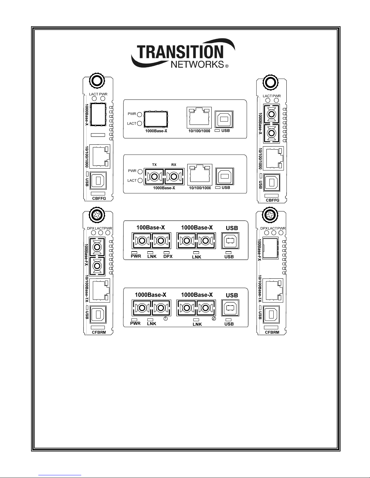
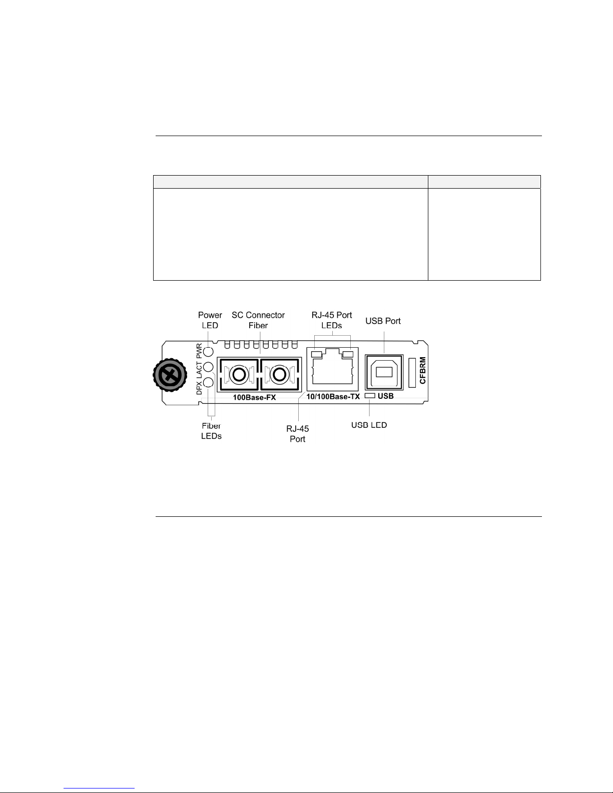
Hardware description
Front panel
CFBRM
The front panel of the CFBRM10xx-1xx devices has the following ports and LEDs:
Ports Front Panel LEDs
One RJ-45 auto-sensing of 10Base or 10/100Base-TX UTP
• Power (one)
• RJ-45 port (two)
connections
One 100Base-FX/LX/BX fiber either SC or ST connectors
• LACT (one)
• DPX (one)
One USB
See Figure 1.
• USB (one)
Figure 1: Chassis CFBRM10xx-1xx Converter Front Panel
Note: The LEDs are the same on the SFBRM10xx-1xx standalone models.
Continued on next page
24-Hour Technical Support: 1-800-260-1312 International: 00-1-952-941-7600 5
Section I: FBRM/BFFG Product Description Transition Networks
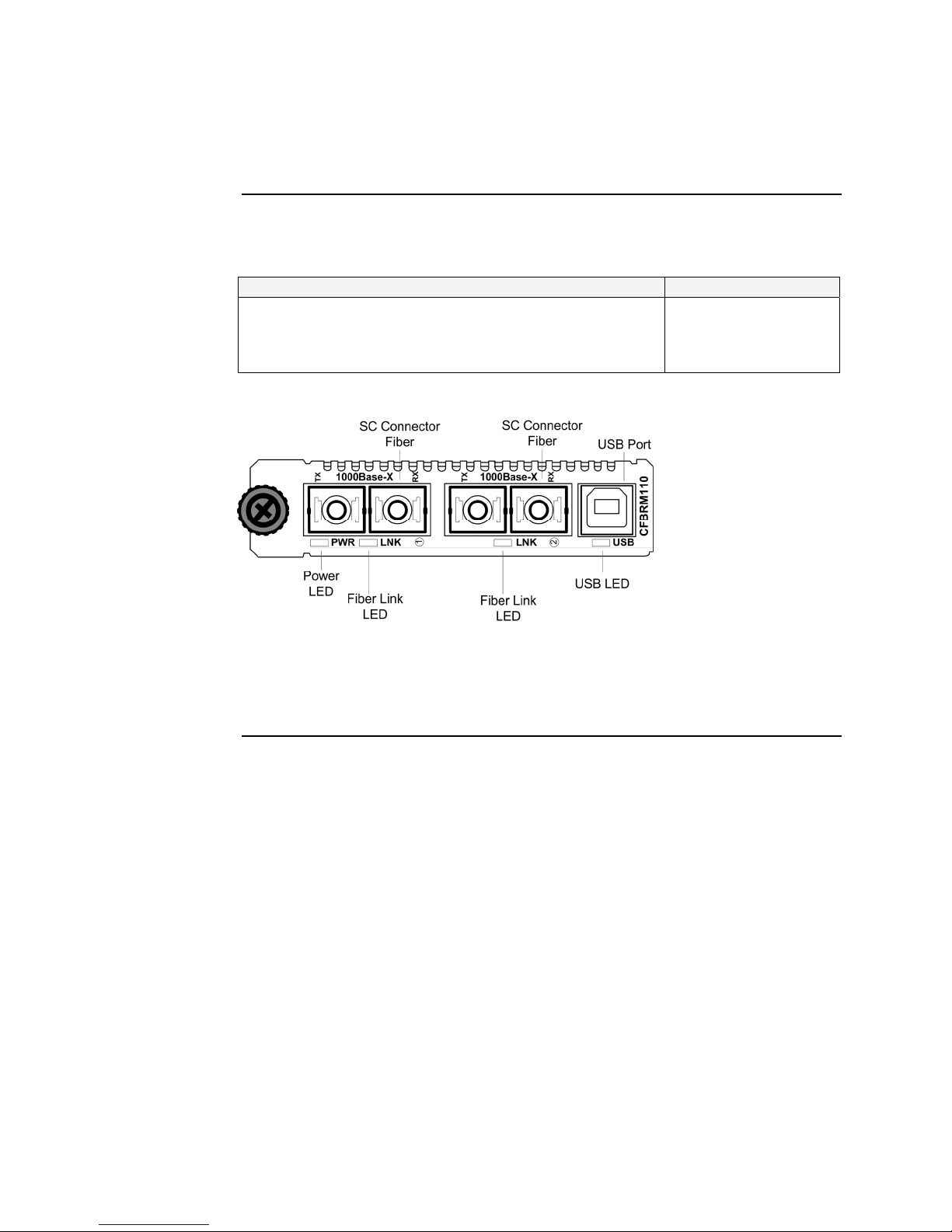
Hardware description, continued
Front panel
CFBRM Gbit
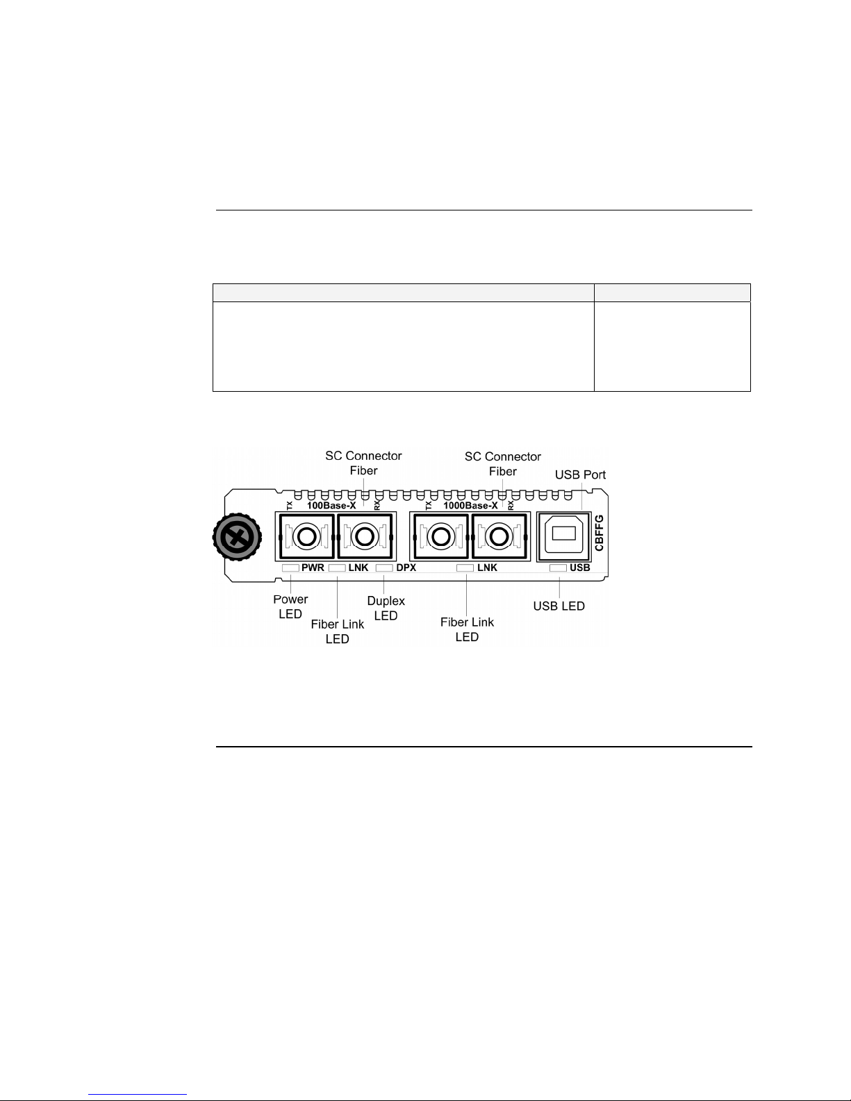
The front panel of the CFBRM13xx-1xx converters has the following ports and
LEDs:
Ports Front Panel LEDs
Two 1000Base-FX/LX/BX fiber either SC or ST connectors
One USB
See Figure 2.
• Power (one)
• Fiber-Port Link (two)
• USB (one)
Figure 2: Chassis CFBRM/CBFFG13xx-1xx Converter Front Panel
Note: The LEDs are the same on the SFBRM13xx-1xx standalone models.
Continued on next page
6

Transition Networks Section I: FBRM/BFFG Product Description
Hardware description, continued
Front panel
CBFFG Gbit
The front panel of the CBFFG10xx-1xx converters has the following ports and
LEDs:
Ports Front Panel LEDs
1000Base-SX/LX/BX fiber SC port
10/100/1000Base-T copper port
• Power (one)
• Link/Active
• Speed
• Duplex (one)
One USB
See Figure 3.
• USB (one)
Figure 3: CBFFG10xx-1xx Converter Front Panel
Note: The LEDs are the same on the SBFFG10xx-1xx standalone models
Continued on next page
24-Hour Technical Support: 1-800-260-1312 International: 00-1-952-941-7600 7
Section I: FBRM/BFFG Product Description Transition Networks
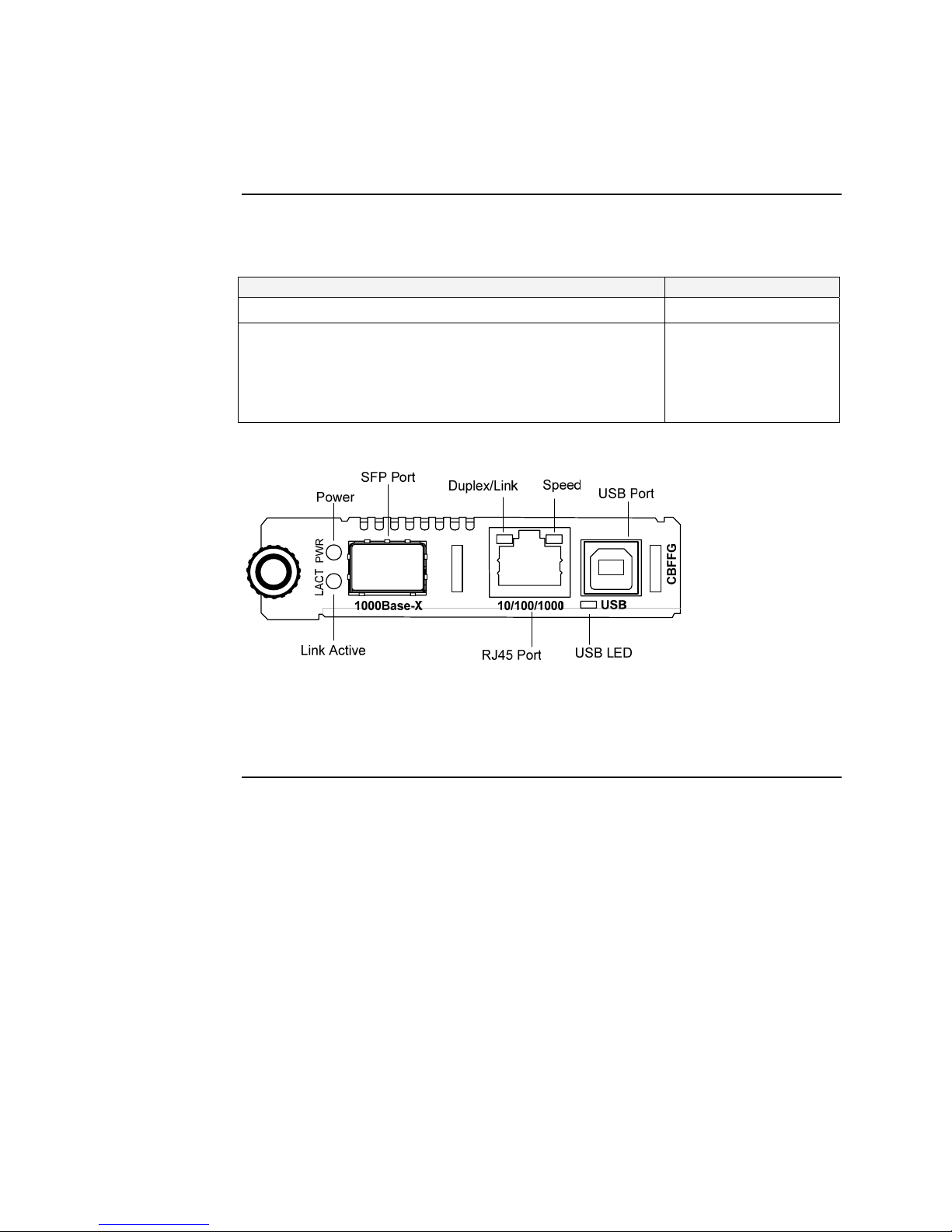
Hardware description, continued
Front panel
CBFFG Gbit
The front panel of the CBFFG1040-1xx converters has the following ports and
LEDs:
Ports Front Panel LEDs
1000Base SFP port
10/100/1000Base-T copper port
• Power (one)
• Link/Active
• Speed
• Duplex (one)
One USB
See Figure 4.
• USB (one)
Figure 4: CBFFB1040-1xx Converter Front Panel
Note: The LEDs are the same on the SBFFG1040-1xx standalone models
Continued on next page
8
Transition Networks Section I: FBRM/BFFG Product Description
Hardware description, continued
Front panel
CBFFG Gbit
The front panel of the CBFFG13xx-1xx converters has the following ports and
LEDs:
Ports Front Panel LEDs
Two 1000Base-FX/LX/BX fiber either SC or ST connectors
• Power (one)
• Fiber-Port Link (two)
• Duplex (one)
One USB
See Figure 5.
• USB (one)
Figure 5: Chassis CBFFG13xx-1xx Converter Front Panel
Note: The LEDs are the same on the SBFFG13xx-1xx standalone models.
Continued on next page
24-Hour Technical Support: 1-800-260-1312 International: 00-1-952-941-7600 9
Section I: FBRM/BFFG Product Description Transition Networks
Hardware description, continued
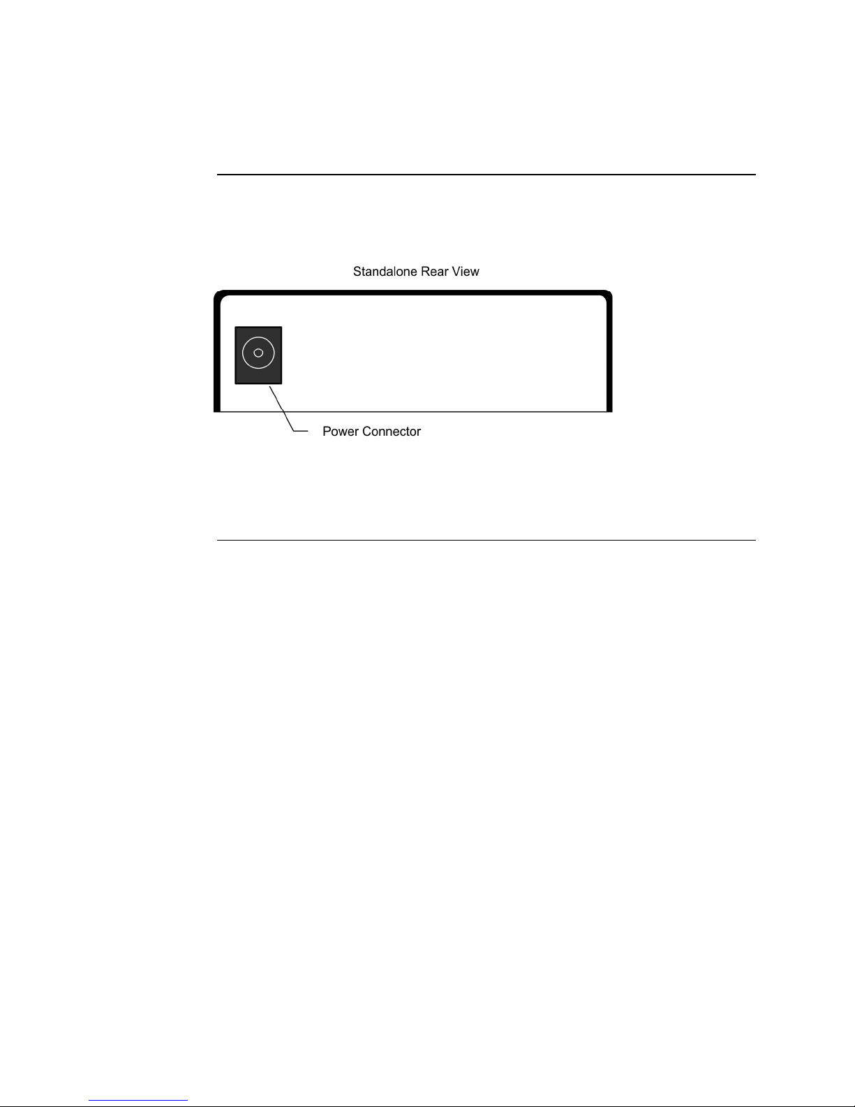
Rear panel
(standalone)
On the standalone SFBRM and SBFFG converters only, the rear panel consists of a
power-barrel connector for connecting power via a power adaptor. See Figure 6.
Figure 6: SFBRM/SBFFG 1xxx-1xx Converter Real Panel (Standalone Only)
Note: The Point System chassis powers the CFBRM and CBFFG chassis cards.
10

Transition Networks Section I: FBRM/BFFG Product Description
FBRM/BFFG13xx-1xx fiber-to-fiber gigabit models
Gigabit (Gbit)
models
The FBRM100Base-FX-to-1000Base-X and the BFFG 1000Base-X-to-1000Base-X
are the Gbit versions of the FBRM series IEEE 802.3ah managed converter. The
BFFG models link Gbit fiber connections; the FBRM models convert 100Base-Fx
100 Mbit/s to Gbit. These converters function generally in the same manner as
copper-to-fiber FBRMs—the difference is the way the ports are configured. See
Tables 1 and 2.
Table 1: FBRM13xx-1xx 100Base-FX-to-1000Base-X Converter
Port Configuration
Port 1: 100Base-FX
• Default setting: 100Mbs and full duplex.
• FEFI (Far-end fault indication) is configurable.
Port 2: 1000Base-X
Default:
• Auto-Negotiation enabled.
• OAM enabled and in Active mode if chassis card (passive if
standalone).
Table 2: BFFG13xx-1xx 1000Base-X-to-1000Base-X Converter
Port Configuration
Port 1: 1000Base-X
Port 2: 1000Base-X
Default: Auto-Negotiation enabled.
Default:
• Auto-Negotiation enabled.
• OAM is enabled and in Active mode if chassis card
(passive if standalone).
Continued on next page
24-Hour Technical Support: 1-800-260-1312 International: 00-1-952-941-7600 11
Section I: FBRM/BFFG Product Description Transition Networks
FBRM/BFFG13xx-1xx fiber-to-fiber gigabit models, continued
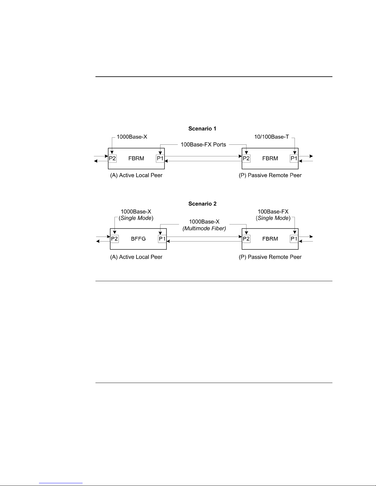
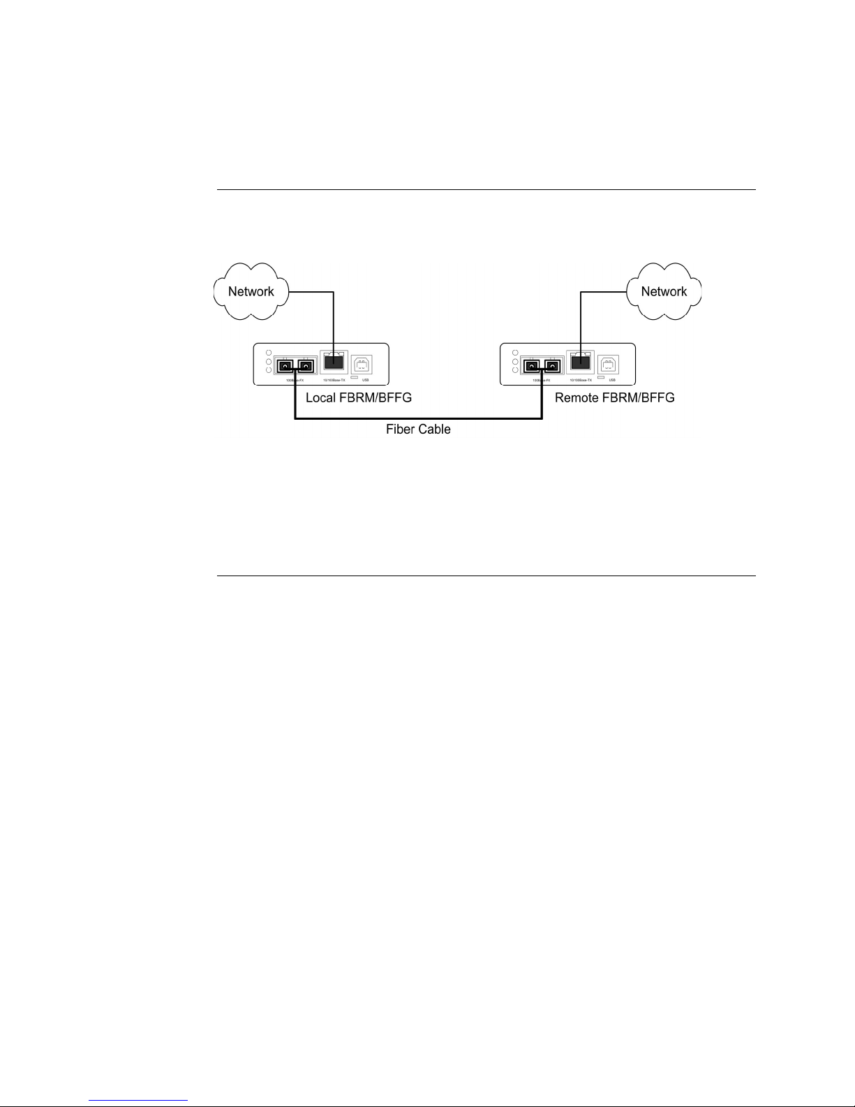
Connectivity
The different versions of the FBRM and BFFG can be connected and set up to
completely manage a remote peer. In a mixed setup with other FBRM or BFFG
converters, consider the connectivity scenarios in Figure 7, and the explanation that
follows:
Connection
scenario
explanation
Figure 7: Connectivity Scenarios
In Figure 7, P2 of the active local peer in both scenarios is “OAM enabled” and
“Active” by default. To manage the remote passive peer via OAM, configure P1 of
the active local peer as follows:
• Enable OAM
• Select Active mode
If the connection to the passive remote peer is made thru P2 of the active local peer,
OAM occurs without human intervention.
Note: Automatic firmware upgrades will not occur with different types of FBRM
or BFFG converter configurations.
12

Introduction
Caution
In this section
Transition Networks
Section II:
Hardware Installation
This section describes how to install the CFBRM and CBFFG converters into a Point
System chassis with a remotely managed SFBRM or GFBRM standalone converter.
Also, shows how to install two SFBRM converters or two SBFFG standalone
converters on a network, one as a local device and the other as a remotely managed
device.
When handling chassis cards observe electrostatic discharge precautions. This
requires proper grounding; i.e., wear a wrist strap.
These are the topics:
Topic See Page
Installing CFBRM/CBFFG cards into a point system chassis 14
Installing SFBRM/SBFFG standalone models 15
Installing copper and fiber cables 16
Connecting power (standalone models) 18
24-Hour Technical Support: 1-800-260-1312 International: 00-1-952-941-7600 13
Section ll: FBRM/BFFG Hardware Installation Transition Networks
Installing CFBRM/CBFFG cards into point system chassis
IMPORTANT
Caution
The CFBRM/CBFFG media-converter product family IS NOT compatible with the
CPSMM-200 and CPSMM-210 MGMT modules when used in a cascaded
application. The CFBRM/CBFFG can be installed in the “master” chassis with the
CPSMM-200 MGMT module, but they can not be installed in a cascaded chassis
using the CPSMM-210 MGMT module.
Alternatively, the CFBRM/CBFFG can be used with the CPSMM120 MGMT
module, which does not support chassis cascading.
Wear a grounding strap and observe electrostatic discharge precautions when
installing the CFBRM/CBFFG converter into the Point System chassis.
Failure to observe this caution could result in damage to the media converter.
Chassis card
installation
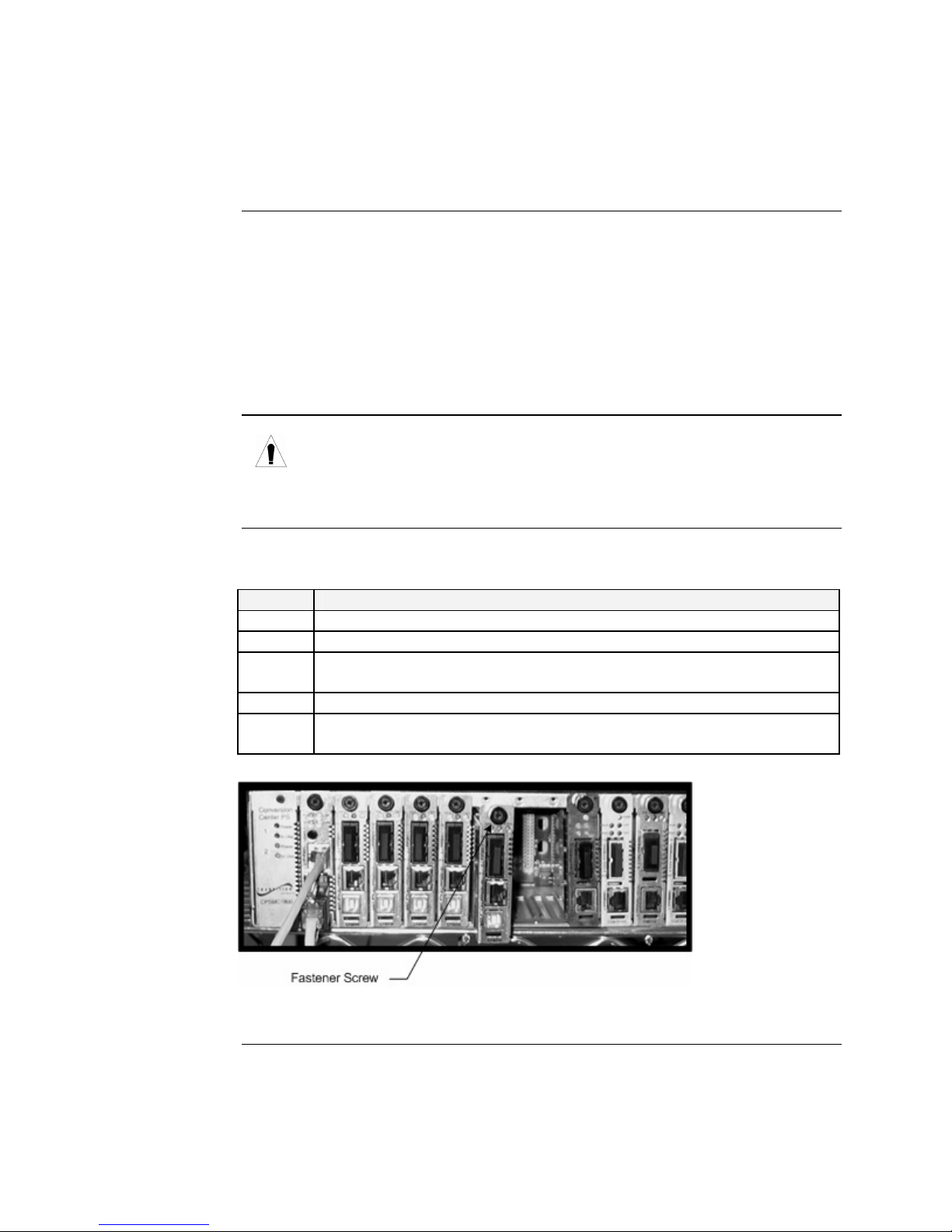
To install the chassis card into the Point System chassis, do the following:
Step Action
1. Locate an empty slot in the Point System chassis.
2. Grasp the edges of the card by its front panel.
3. Align the module with the slot guides and carefully insert the card into the
installation slot.
4. Firmly seat the card against the chassis back panel.
5. Push IN and ROTATE clockwise the panel-fastener screw to secure the
card. See Figure 8.
Figure 8: CFBRM/CBFFG Media Converter Chassis Installation
14
Transition Networks Section ll: FBRM/BFFG Hardware Installation
Installing SFBRM/SBFFG standalone models
Standalone
installation
Figure 9 shows a typical installation involving two (2) SFBRM/SBFFG standalone
media converters on a network.
Figure 9: Installation with Two SFBRM/SBFFG Standalone Media Converters
Note: With the local active standalone device connected to a remote standalone
passive device and with “Mode Control” set to “Auto,” the local (active)
device will manage the remote (passive) device. This relationship is
established automatically.
24-Hour Technical Support: 1-800-260-1312 International: 00-1-952-941-7600 15
Section ll: FBRM/BFFG Hardware Installation Transition Networks
Installing fiber and copper cables
Warning
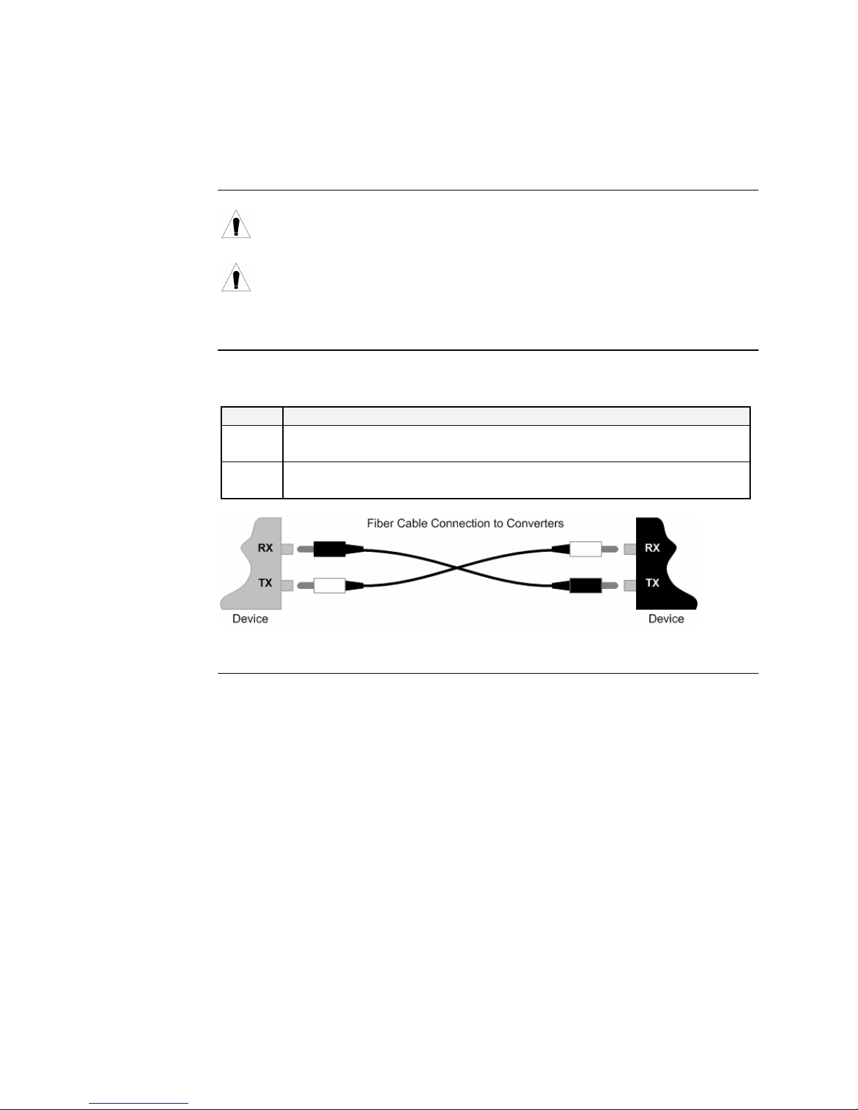
Fiber cable
Use of controls, adjustments or the performance of procedures other than
those specified herein may result in hazardous radiation exposure.
Visible and invisible laser radiation when open: DO NOT stare into the laser-
light beam or view the beam directly with optical instruments. Failure to
observe this warning could result in an eye injury or blindness.
To install the fiber cable, do the following:
Step Action
1. Locate a 100Base-FX/SXLX compliant fiber cable with male, two-
stranded connectors installed at both ends. See Figure 10.
2. Connect the fiber cables to the FBRM or BFFG media converters as
shown in Figure 10.
Figure 10: Fiber Cable Installation
Continued on next page
16
Transition Networks Section ll: FBRM/BFFG Hardware Installation
Installing fiber and copper cables, continued
Caution
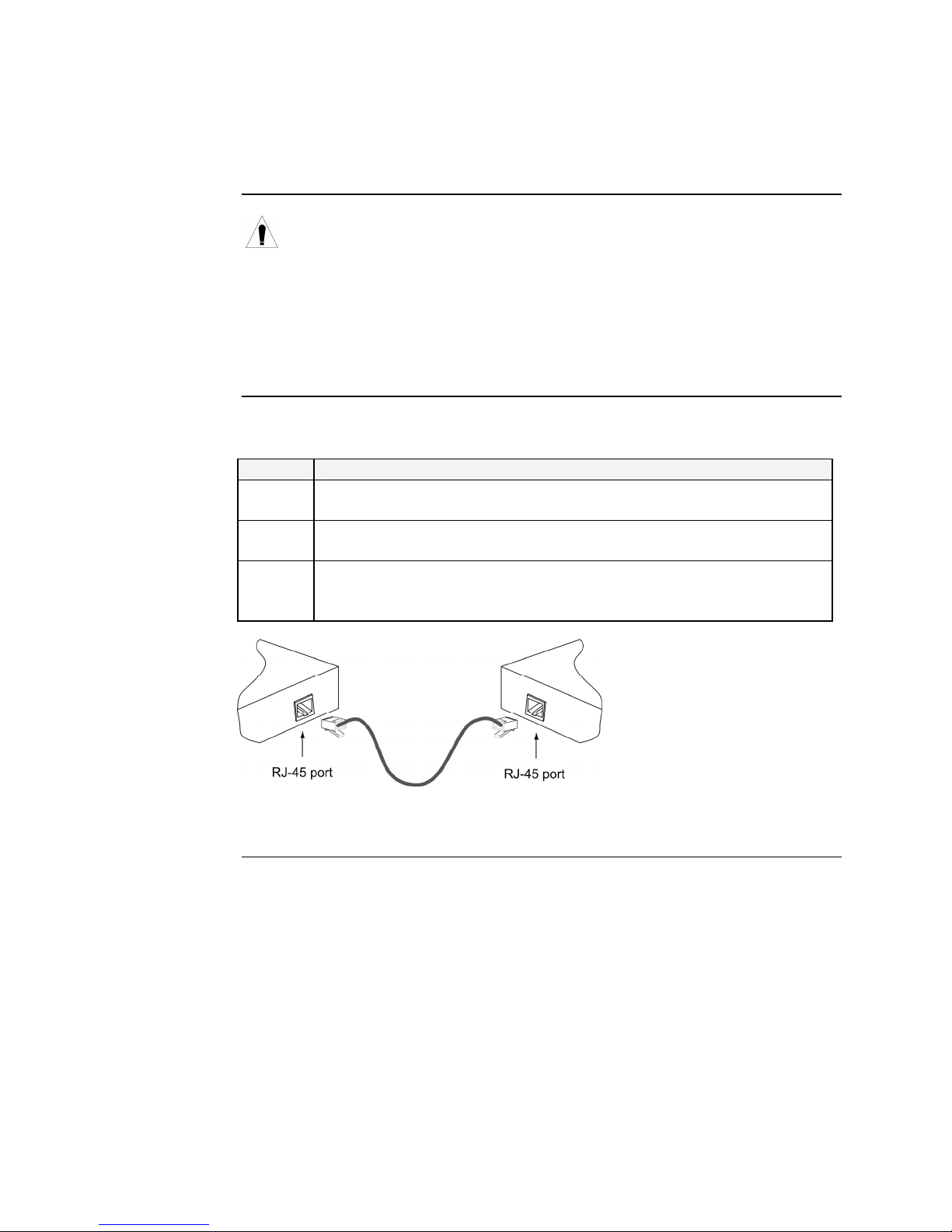
Copper cable
Copper based media ports, e.g., Twisted Pair (TP) Ethernet, USB, RS232,
RS422, RS485, DS1, DS3, Video Coax, etc., are intended to be connected to
intra-building (inside plant) link segments that are not subject to lightening
transients or power faults.
Copper based media ports, e.g., Twisted Pair (TP) Ethernet, USB, RS232,
RS422, RS485, DS1, DS3, Video Coax, etc., are NOT to be connected to
inter-building (outside plant) link segments that are subject to lightening.
To install the copper cable, do the following:
Step Action
1. Locate a 10/100Base-T compliant copper cable with male, RJ-45
connectors installed at both ends.
2. Connect the RJ-45 connector at one end of the cable to the media
converter’s 10/100Base-T RJ-45 port.
3. Connect the RJ-45 connector at the other end of the cable to the 10/100
Base-T RJ-45 port on the other device (switch, workstation, etc.). See
Figure 11.
Figure 11: Copper Cable Installation
24-Hour Technical Support: 1-800-260-1312 International: 00-1-952-941-7600 17
Section ll: FBRM/BFFG Hardware Installation Transition Networks
Connecting power (standalone models)
Chassis powers
slide-in module
Adapter powers
standalone
Transition Networks’ Point System chassis powers the CFBRM/CBFFG chassis
cards.
Use an AC power adaptor to power the SFBRM/SBFFG standalone converter. To
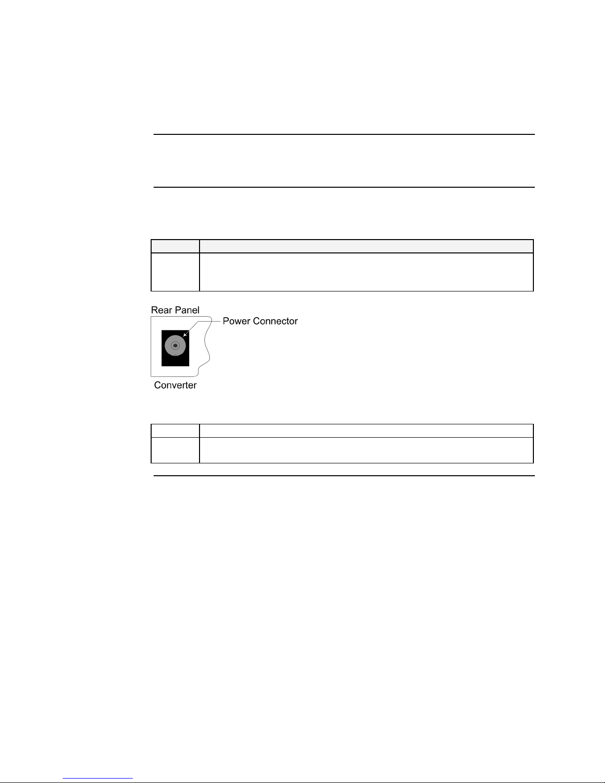
connect power to the converter, do the following:
Step Action
1. Connect the barrel connector on the power adapter cord to the power
connector on the media converter (located on the rear of the media
converter). See Figure 12.
Figure 12: Standalone Converter Power Connector
2. Connect the power adapter plug into AC power.
3. Verify that the media converter has powered UP—the power indicator
LED will be lit.
18

Transition Networks Section ll: FBRM/BFFG Hardware Installation
Intentionally Blank
24-Hour Technical Support: 1-800-260-1312 International: 00-1-952-941-7600 19

Transition Networks
Section III:
USB Driver Installation & COM Port Setup
Introduction
In this section
This section shows how to install the USB driver and configure COM ports.
These are the topics:
Topic See Page
Installing USB driver 21
Configuring COM ports 25
24-Hour Technical Support: 1-800-260-1312 International: 00-1-952-941-7600 20
Transition Networks Section lll: FBRM/BFFG1 Driver Installation & COM Port Setup
Installing USB driver
USB driver
Installing USB
driver
The driver installation instructions are for Windows XP only. Installing the USB
driver using Windows 2000 is similar, but not necessarily identical to the following
Windows XP procedure.
Note: The following USB drivers are provided with the product on a CD, also
available at www.ftdichip.com: WinXP64, Win Server 2003, Win 2002,
Win ME/98, Mac OS X, 9, 8, and Linux.
To install the USB driver on a computer with a Windows XP OS, do the following:
Step Action
1. Extract the driver (provided CD or from website) and place it in an
accessible folder on the local drive.
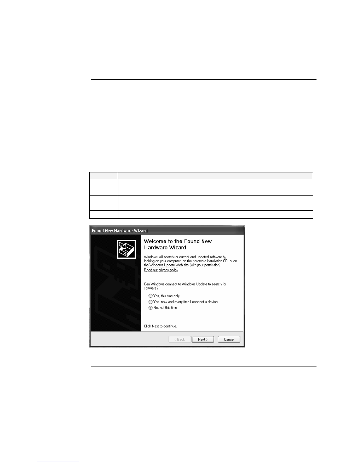
2. Plug the media converter into the USB port on the PC to bring up the
“found new hardware” wizard dialog box, shown in Figure 13.
3. Select RADIO button, “No, not this time” as shown in Figure 13.
Figure 13: Found New Hardware Wizard Dialog Box
24-Hour Technical Support: 1-800-260-1312 International: 00-1-952-941-7600 21
Continued on next page
Section lll: FBRM/BFFG USB Driver Installation & COM Port Setup Transition Networks
Installing USB driver, continued
Installing USB driver (continued)
Step Action
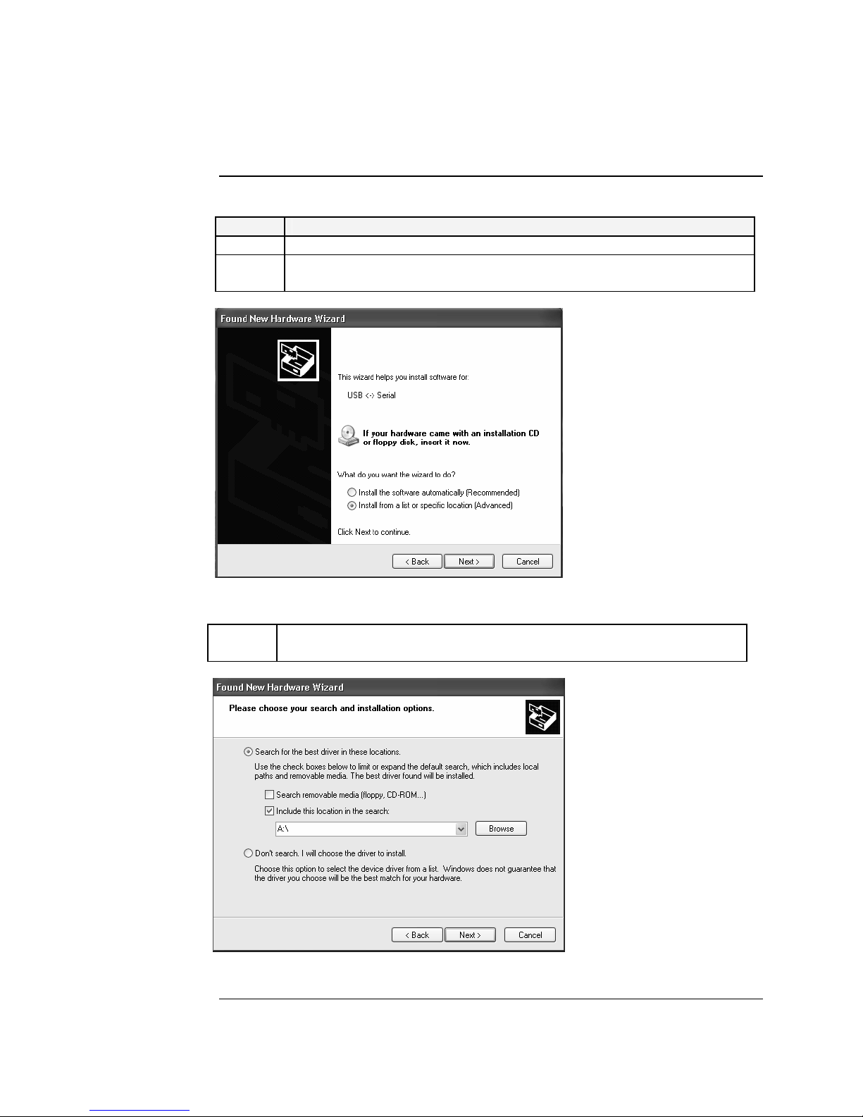
4. Click the NEXT button to launch the “installation options” dialog box.
5. Select RADIO button “Install from a list or specific location
(Advanced)” as shown in Figure 14.
Figure 14: Installation Options Dialog Box
6. Click the NEXT button to bring up the “driver search installation
options” dialog box, shown in Figure 5.
Figure 15: Driver Search Installation Options Dialog Box
Continued on next page
22
Transition Networks Section lll: FBRM/BFFG1 Driver Installation & COM Port Setup
Installing USB driver, continued
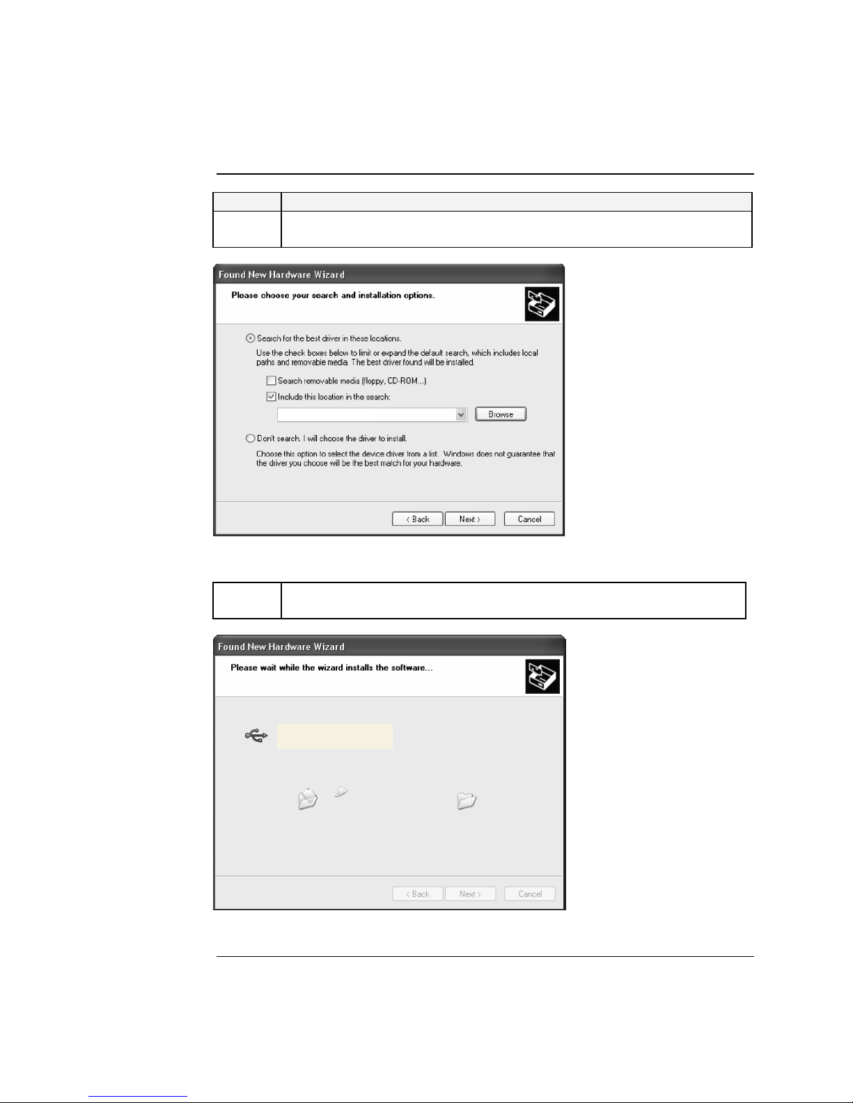
Step Action
7. Use the BROWSE button to locate the USB driver, as shown in
Figure 16.
C:\FBRM/BFFG1xx
Figure 16: Driver Location
8. Click the NEXT button to start installing the driver and the driver-install
screen will appear as XP copies the device driver. See Figure 17.
FBRM/BFFG1xx Driver
Figure 17: Windows XP Installing Driver Box
Continued on next page
24-Hour Technical Support: 1-800-260-1312 International: 00-1-952-941-7600 23
Section lll: FBRM/BFFG USB Driver Installation & COM Port Setup Transition Networks
Installing USB driver, continued
Step Action
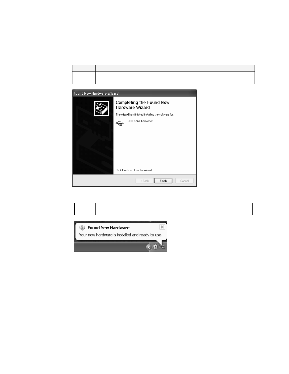
9. After the driver installation is successful, the “finished installing” dialog
box will appear, as shown in Figure 18.
Figure 18: Finish Installing Driver Dialog Box
10. Click the FINISH button and a “found new hardware” message will
appear on the lower right side of the screen, as shown in Figure 19.
Figure 19: New Hardware Installed and Ready to Use
24
 Loading...