

Transition Networks AS4TEF1015-100, AS4TEF1011-100, AS4TEF1016-100, AS4TEF1017-100, AS4TEF1018-100 User Manual
...Page 1
* Typical maximum cable distance. Actual distance is dependent upon the
physical characteristics of the network.
The chassis version of the media
converter is C4TEF10xx-10x. For more
information, see the user’s guide on-line
at: www.transition.com.
Installation . . . . . . . . . . . . . . . . . .2
Operation . . . . . . . . . . . . . . . . . .10
Cable Specifications . . . . . . . . . .12
Technical Specifications . . . . . . .14
Troubleshooting . . . . . . . . . . . . .15
Compliance Information . . . . . . .19
User’s Guide
AS4TEF10xx-10x
Stand-Alone Media Converter
• RS-232 to Fiber
• (4) T1/E1 to Fiber
The AS4TEF10xx-10x media converter can
extend signals from an RS-232 data port and
up to four (4) T1/E1 network ports over fiber.
The RS-232 and T1/E1 interfaces are independent of each other and the signals
from these ports can be sent over the fiber interface simultaneously.
The AS4TEF10xx-10x is designed to be installed in pairs. For example, install one
S4TEF1011-100 as the local media converter and another S4TEF1011-100 as the
remote media converter.
All S4TEF10xx-10x models have the following copper connectors:
The various fiber connectors are available on separate models. Both duplex and
single mode fiber optic converters are available:
Part Number Duplex Fiber-Optic - 100Base-FX
AS4TEF1011-100 ST, 1300 nm multimode, 2 km (1.2 miles)*
AS4TEF10173-100 SC, 1300 nm multimode, 2 km (1.2 miles)*
AS4TEF1014-100 SC, 1310 nm single mode, 20 km (12.4 miles)*
AS4TEF1015-100 SC, 1310 nm single mode, 40 km (24.8 miles)*
AS4TEF1016-100 SC, 1310 nm single mode, 60 km (37.2 miles)*
AS4TEF1017-100 SC, 1550 nm single mode, 80 km (49.7 miles)*
AS4TEF1018-100 MT-RJ, 1300 nm multimode, 2 km (1.2 miles)*
Connector Type Number Description
RS-232 one (1) 6-pin, DIN serial, 3.2 m (10 ft.)*
T1/E1 four (4) RJ-48
AS4TEF1029-10x (single mode, single fiber models are listed on page 2)
Page 2
NOTE: An RS-232 cable with a 6-pin DIN connector and a DB-9 connector is
included with the S4TEF10xx-10x media converter.
2
S4TEF10xx-10x
.
PWR
LKF
100Base-FX
TX
RX
4
3
2
1
LNKLNKLNKLNK AISAISAISAIS
fiber port
T1/E1 ports
RS-232
RS-232 port
Part Number Fiber-Optic - single fiber, single mode, 100Base-FX
AS4TEF1029-100 SC, 1310 mn (TX)/1550 nm (RX), 20 km (12.4 miles)*
AS4TEF1029-101 SC, 1550 mn (TX)/1310 nm (RX), 20 km (12.4 miles)*
S4TEF1029-100 and S4TEF1029-101 are intended to be
installed in the same link where one is the local converter
and the other is the remote converter.
AS4TEF1029-102 SC, 1310 mn (TX)/1550 nm (RX), 40 km (24.8 miles)*
AS4TEF1029-103 SC, 1550 mn (TX)/1310 nm (RX), 40 km (24.8 miles)*
S4TEF1029-102 and S4TEF1029-103 are intended to be
installed in the same link where one is the local converter
and the other is the remote converter.
Installation
Due to proprietary communication over fiber, the S4TEF media converter must
be installed in pairs.
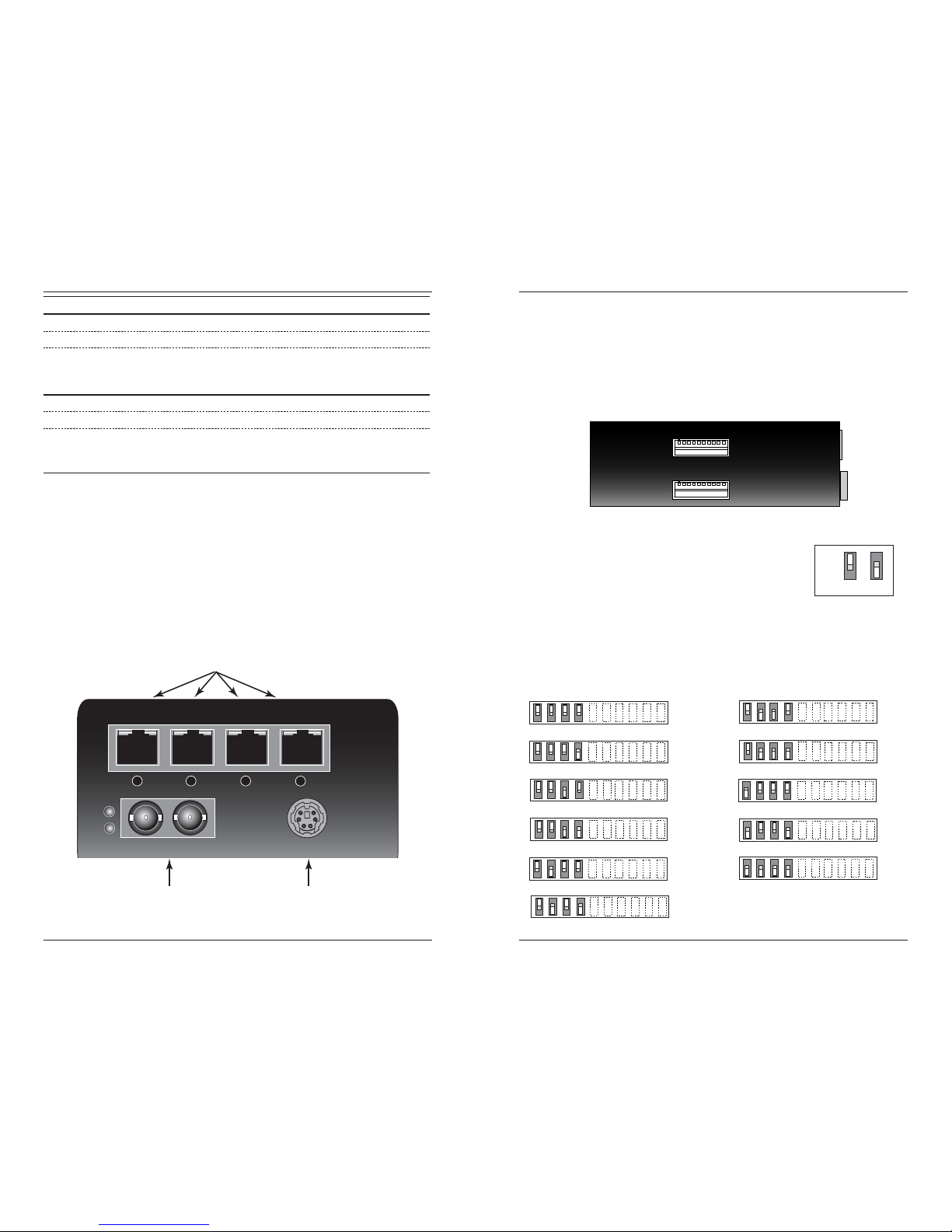
Copper and Fiber Ports
The figure below illustrates the locations of the fiber port, the RS-232 data port,
and the four (4) T1/E1 ports.
* Typical maximum cable distance. Actual distance is dependent upon the
physical characteristics of the network. (TX) = transmit, (RX) = receive
3
.
Installation -- Continued
Configuration Switches
The AS4TEF10xx-10x media converter has two (2) sets of configuration switches.
• Set #1 sets the T1/E1 options.
• Set #2 sets the serial options.
Use a flat blade screwdriver to set the switches as shown:
Switch Set #1 - T1/E1 Options
1, 2, 3, 4 - Line Settings
Switches 1, 2, 3, and 4 are used to setup the line settings for the T1/E1 ports. The
selected setting applies to all four (4) T1/E1 channels.
Switch Set #1 (upper): T1/E1 Options
Switch Set #2 (lower): Serial O
p
tions
Key:
up
down
DSX-1, 100 ohm, 266-399 ft. (81-122 m)
DSX-1, 100 ohm, 399-533 ft. (122-162 m)
DSX-1, 100 ohm, 0-133 ft. (0-40.5 m)
DSX-1, 100 ohm, 133-266 ft. (40.5-81 m)
1 2
DS1, 100 ohm, 0 dB LBO
DS1, 100 ohm, -7.5 dB LBO
DSX-1, 100 ohm, 533-655 ft. (162-200 m)
J1, 110 ohm, 0-655 ft. (0-200 m)
3
E1, 120 ohm
DS1, 100 ohm, -15 dB LBO
DS1, 100 ohm, -22.5 dB LBO
41234
Page 3
4
S4TEF10xx-10x
.
Installation -- Continued
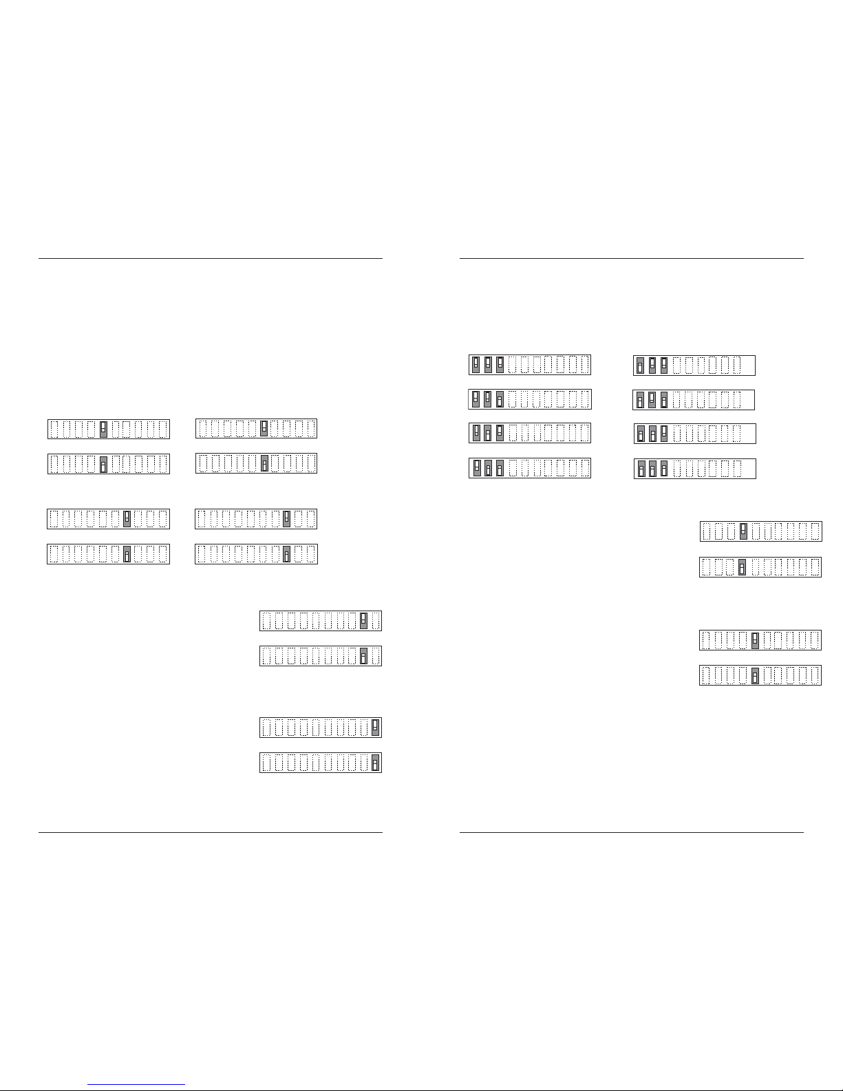
Switch Set #1 - T1/E1 Options
5, 6, 7, 8 - Loop-Back Settings
The loop-back setting is used for installation and network debugging procedures.
Each of the T1/E1 ports can be individually set for loop-back mode:
• Switch 5 controls T1/E1 port 1 • Switch 6 controls T1/E1 port 2
• Switch 7 controls T1/E1 port 3 • Switch 8 controls T1/E1 port 4
When the loop-back switch for a particular T1/E1 port is enabled, the port loops
the signal from the receive port back to the transmit port. The loop-back test
scenarios are described in detail on page 16.
Disable Loop-Back on T1/E1 port 1
Enable Loop-Back on T1/E1 port 1
up
5
down
Disable Loop-Back on T1/E1 port 2
Enable Loop Back on T1/E1 port 2
6
up
down
up
down
Disable Loop-Back on T1/E1 port 3
Enable Loop-Back on T1/E1 port 3
7
up
down
Disable Loop-Back on T1/E1 port 4
Enable Loop-Back on T1/E1 port 4
8
9 - Transmit AIS
up - Enables the transmit AIS (Alarm Indication
Signal) on loss of the carrier signal. This function
is un-framed and applies to ALL channels, both
copper and fiber.
down - Disables the transmit AIS function.
10 - RS-232 Port Mode
up - Data port mode (normal operation).
Transmits data to a desk top computer or other
data collection device
down - Local (auxiliary) management mode. See
the SNMP section (page 11) for the commands
that are supported via the RS-232 connector.
up
down
Enable
Disable
9
up
down
Data port mode
Local management mode
10
5
.
Installation -- Continued
Switch Set #2 - Serial Options
1, 2, 3 - Serial Connection Speed Line Settings
Switches 1, 2, and 3 on switch set #2 are used to set the serial connection speed.
4800 baud
9600 baud
1200 baud
2400 baud
1 2 3
57600 baud
115200 baud
19200 baud
38400 baud
1 2 3
4. Enable / Disable Parity
When parity is enabled, an additional bit is added to
the 8-bit signal to identify whether the signal is sent
successfully. Use switch 5 to send odd or even
signal parity.
up - Enable parity.
down - Disable parity.
5. Parity Select
up - Select odd serial parity.
down - Select even serial parity.
This switch is inactive if switch 4 is disabled (down).
Enable Parity
Disable Parity
down
up
4
Odd Serial Parity
Even Serial Parity
up
5
down
Page 4

6
S4TEF10xx-10x
Installation -- Continued
Switch Set #2 - Serial Options
6 - not in use
7 - not in use
8 - not in use
9 - not in use
switches 6, 7, 8, & 9 are not in use
9876
10 - Fiber Loop-Back
up - Enables fiber loop-back.
down - disables fiber loop-back.
The loop-back setting is used for installation
and network debugging procedures. When
the fiber loop-back function is enabled, the
fiber port loops all T1/E1 signals from the
receive ports back to the transmit ports. The
loop-back test scenarios are described in
detail on page 17.
up
down
Disables Loop-Back
Enables Loop-Back
10
7
.
Installation -- Continued
Hardware/Software Jumper
The hardware/software jumper is inside the media converter housing and is
located near the back end of the upper circuit board.
Hardware The media converter mode is determined by
the switch settings (see pages 3 - 6).
Software The media converter mode is determined by
the most-recently saved, on-board
microprocessor settings.
Hardware Mode
Software Mode
S
H
S
H
To set the jumper:
1. Using a small screwdriver, remove the four (4)
screws that secure the cover and carefully
remove the cover from the media converter.
2. Locate the hardware/software jumper.
3. Using small needle-nosed pliers or similar
device, move the jumper to the desired position
(see above).
4. Carefully replace the cover on the media
converter and replace the four (4) screws that
secure the cover to the media converter.
Power the Media Converter
1. Connect the barrel connector on the power adapter to the media
converter’s power port (located on the back of the media converter).
2. Connect the power adapter plug to AC power.
3. Verify that the media converter is powered by observing the illuminated
LED power indicator light.
NOTE: For DC power, consult the user’s guide for the Transition Networks
SPS1872-xx DC external power supply.
hardware/software
jumpe
r
Page 5

8
S4TEF10xx-10x
.
Installation -- Continued
Install the T1/E1 Cable
1. Locate or build ITU-compliant copper cable with straight-through RJ-48
connectors installed at both ends. (See page 13 for the proper cable
specifications for your network application.)
2. Connect the RJ-48 connector at one end of the cable to one of the T1/E1
ports on the S4TEF10xx-10x media converter.
3. Connect the RJ-48 connector at the other end of the cable to the T1/E1
port on the other device.
Install the RS-232 Data Cable (included)
1. Use the enclosed RS-232 data cable with a male, DIN 6-pin connector
on one end and a DB-9 connector installed on the other end.
2. Connect the DIN 6-pin connector to the RS-232 port on the S4TEF10xx10x media converter.
3. Connect the DB-9 connector at the other end of the cable to the RS-232
port on a computer or other device that is used to collect and display
data.
Dry-Contact Relay
All four T1/E1 ports are equipped with an
RJ-48 dry-contact relay. The relay closes if
the power is lost or if any of the individual
T1/E1/E1 links are lost. The operational
rating on pins 3 and 6 are 0-30 VDC, 100
mA (maximum).
relay
3
6
RJ-48C connector
T1/E1 port
Connect the 6-pin DIN
connector to the media
converter as shown.
Connect the DB-9
connector to the
computer
RS-232 data cable (enclosed)
9
.
Installation -- Continued
Install the Fiber Cable
1. Locate or build ITU- compliant 100Base-FX fiber cable with male, twostranded TX to RX connectors installed at both ends.
2. Connect the fiber cables to the local S4TEF10xx-10x media converter as
described:
• Connect the male TX cable connector to the female TX port.
• Connect the male RX cable connector to the female RX port.
3. Connect the fiber cables to the remote S4TEF10xx-10x media converter
as described:
• Connect the male TX cable connector to the female RX port.
• Connect the male RX cable connector to the female TX port.
Connect the fiber cable
to the local media
converter as shown.
Connect the fiber cable
to the remote media
converter as shown
RX
TX
RX
TX
Page 6

10
S4TEF10xx-10x
.
Operation
T1/E1 LEDs
Each T1/E1 link has a pair of LEDs embedded in the RJ-48 connector that
monitor the status of the link.
LNK LED (green)
On = T1/E1 link detected.
AIS LED (amber)
On = AIS (Alarm Indication Signal) detected. Failure of the device
connected to the T1/E1 port.
Fiber Network LEDs
Use the status LEDs next to the fiber port to monitor the media converter and
the fiber network connections.
LKF (fiber link)
On = Fiber link connection.
Flashing = Fiber network activity.
PWR (power)
On = Connection to external AC or DC power.
PWR
LKF
100Base-FX
TX
RX
4
3
2
1
LNKLNKLNKLNK AISAISAISAIS
fiber LEDs
T1/E1 LEDs
RS-232
11
Operation -- Continued
Remote Management Function
The S4TEF10xx-10x, can be remotely managed when connected via fiber cable
to a local C4TEF10xx-10x slide-in-module media converter that is installed in a
managed Transition Networks PointSystem™ chassis. The SNMP section
(below) lists the commands that can be used to monitor and manage a
networked S4TEF10xx-10x media converter at a remote location. For more
details, see the C4TEF10xx-10x user’s guide on-line at: www.transition.com.
SNMP
See the on-line documentation that comes with Transition Networks
FocalPoint™ software for applicable commands and usage.
Use SNMP at an attached terminal or at a remote location to monitor the media
converter by monitoring:
• Media converter power
• Fiber link status
• Copper link status for each T1/E1 (AIS, link)
• RS-232 status (speed, bits, parity, stop)
• AIS detected on fiber link
• All hardware switch settings
• Model #, serial #, PIC revision, HW revision, group string, connectors
Also, use SNMP to enter network commands that:
• Local and remote fiber loop-back
• Local and remote T1/E1 loop-back for each channel
• T1/E1 line options (DS1, DSX-1, J1, D1, AIS)
• RS-232 settings (speed, bits, parity, stop)
• T1/E1 monitor modes and loop-back modes
• Boot-load firmware (local unit only)
The local (auxiliary) factory maintenance interface via the RS-232 connector
supports:
• Switch selection for the RS-232 interface
• Access to all local and remote status information
• Perform all local and remote commands
• Operate at selected baud rates
Page 7

13
.
Cable Specifications -- Continued
T1/E1 Cable
Category 3: (minimum requirement)
Connector: RJ-48C
Electrical network connection: Single 4-wire (Tip/Ring - Tip1/Ring1)
Mechanical arrangement: 8-position miniature modular jack
Usage: 1.544 Mb/s access lines
Interface codes: 04DU9 (any applicable)
Cable type:
Long Haul T1/E1: 0db, -7.5dp, -15db, -22db
E1: E1 3.0V, 120 ohm
J1: 0-655’, 110 ohm
DSX-1: 0-133’, 133-266’, 266-399’,
399-533’, 533-655’, 100 ohm
4
5
Receive
Transmit
4
5
(ring) R1
(tip) T1
1
(ring) R
1
R
2
(tip) T
2
T
R1
T1
from the
media converter
to the
network
3
3
6
6
7
7
8
8
dry contact A
dry contact B
(not used)
RS-232 Cable
(included)
Connectors: 6-pin DIN and DB-9
Gauge: 24 to 22 AWG
Attenuation: 20 dB/1000 ft. @ 10 MHz
Differential characteristic impedance: 100 ohm +/- 10% @ 10 MHz
Maximum cable distance: <10 ft (3.2 m) @ 56 kb/s or higher
DB-9DIN 6-pin
9
8
7
6
1
5
4
3
2
2
1
4 6
3 5
Clear to Send Signal Ground
59
Receive Signal Transmit Data
32
Transmit Signal Request to Sen
d
7
1
Signal Ground Receive Data
23,5
12
S4TEF10xx-10x
.
Cable Specifications
The physical characteristics must meet or exceed ITU specifications.
Fiber Cable
Bit Error Rate: <10-9
Single mode fiber (recommended): 9 µm
Multimode fiber (recommended): 62.5/125 µm
Multimode fiber (optional): 100/140, 85/140, 50/125 µm
AS4TEF1011-100 1300 nm multimode
Fiber Optic Transmitter Power: min: -19.0 dBm max: -14.0 dBm
Fiber Optic Receiver Sensitivity: min: -30.0 dBm max: -14.0 dBm
Link Budget: 11.0 dB
AS4TEF1013-100 1300 nm multimode
Fiber Optic Transmitter Power: min: -19.0 dBm max: -14.0 dBm
Fiber Optic Receiver Sensitivity: min: -30.0 dBm max: -14.0 dBm
Link Budget: 11.0 dB
AS4TEF1014-100 1310 nm single mode
Fiber-optic Transmitter Power: min: -15.0 dBm max: -8.0 dBm
Fiber-optic Receiver Sensitivity: min: -31.0 dBm max: -8.0 dBm
Link Budget: 16.0 dB
AS4TEF1015-100
(long haul)
1310 nm single mode
Fiber-optic Transmitter Power: min: -8.0 dBm max: -2.0 dBm
Fiber-optic Receiver Sensitivity: min: -34.0 dBm max: -7.0 dBm
Link Budget: 26.0 dB
AS4TEF1016-100
(extra long haul)
1310 nm single mode
AS4TEF1017-100
(long wave length)
1550 nm single mode
Fiber-optic Transmitter Power: min: -5.0 dBm max: 0.0 dBm
Fiber-optic Receiver Sensitivity: min: -34.0 dBm max: -7.0 dBm
Link Budget: 29.0 dB
S4TEF1018-100 1300 nm multimode
Fiber-optic Transmitter Power: min: -19.0 dBm max: -14.0 dBm
Fiber-optic Receiver Sensitivity: min: -30.0 dBm max: -14.0 dBm
Link Budget: 11.0 dB
AS4TEF1029-100 13170 nm (TX)/1550 nm (RX) simplex
AS4TEF1029-101 1550 nm (TX)/1310 nm (RX) simplex
Fiber-optic Transmitter Power: min: -13.0 dBm max: -6.0 dBm
Fiber-optic Receiver Sensitivity: min: -32.0 dBm max: -3.0 dBm
Link Budget: 19.0 dB
AS4TEF1029-102 1310 nm (TX)/1550 nm (RX) simplex
AS4TEF1029-103 1550 nm (TX)/1310 nm (RX) simplex
Fiber-optic Transmitter Power: min: -8.0 dBm max: -3.0 dBm
Fiber-optic Receiver Sensitivity: min: -33.0 dBm max: -3.0 dBm
Link Budget: 25.0 dB
The fiber optic transmitters on this device meets Class I Laser safety
requirements per IEC-825/CDRH standards and complies with 21
CFR1040.10 and 21CFR1040.11.
Page 8

14
S4TEF10xx-10x
.
Technical Specifications
For use with Transition Networks Model S4TEF10xx-10x or equivalent.
Standards G.703, AMI/B8Zs/HDB3
Data Rate Fiber: 100 Mb/s
Dimensions 3.7" x 4.7" x 1.8" (93 mm x 120 mm x 47 mm)
Weight 1 lb. (0.45 kg) (approximate)
Power Consumption 6.0 watts
Power Supply 12 VDC, 0.8 Amp (North. Am., EU, Latin Am., Japan)
12 VDC, 1.25 Amp (UK, Australia, N.Z., South Africa)
(The external power supply provided with this product
is UL listed by the power supplier’s manufacturer.)
Environment Tmra*: 0 to 50°C (32 to 122°F )
Storage Temperature: -40 to 85°C (-40 to 185°F)
Humidity: 5 to 95%, non condensing
Altitude: to 10,000 feet
Warranty Lifetime
*Manufacturer’s rated ambient temperature.
The information contained in this user’s guide is subject to change. For the most
up-to-date information on the S4TEF10xx-10x media converter, see the user’s
guide on-line at: www.transition.com.
Product is certified by the manufacturer to comply with DHHS Rule 21/CFR,
Subchapter J applicable at the date of manufacture.
CAUTION: Visible and invisible laser radiation when open. Do not stare into
beam or view directly with optical instruments.
CAUTION: Use of controls, adjustments or the performance of procedures other
than those specified herein may result in hazardous radiation exposure.
Optional Accessories
The following items are available from Transition Networks
Part Number Description
SPS-1872-SA Optional External Power Supply; 18-72VDC Stand-Alone
Output: 12.6VDC, 1.0 A
WMBL Optional Wall Mount Bracket; 4.0 in. (102 mm)
WMBV Optional Vertical Mount Bracket; 5.0 in. (127 mm)
WMBD Optional DIN Rail Mount Bracket; 5.0 in. (127 mm)
15
.
Troubleshooting
If the media converter fails, isolate and correct the failure by determining the
answers to the following questions and then taking the indicated action:
1. Is the “PWR” LED illuminated?
NO
• Ensure that the power adapter is the proper type of voltage and cycle
frequency for the outlet (See “Power Supply” on page 14.)
• Ensure the power adapter is properly installed in the media converter
and in the grounded outlet.
.
YES
• Proceed to step 2.
2. Is the “LKF” LED illuminated?
NO
• Check the fiber cables for proper connection.
• Verify that the TX and RX cables on the local media converter are
connected to the RX and TX ports, respectively, on the remote media
converter.
YES
• Proceed to step 3.
3. Is the “LNK” LED on a T1/E1port (with a copper cable installed)
illuminated?
NO
• Check the copper cable connected to that T1/E1 port for proper
connection.
• .
YES
• Proceed to step 4.
4. Is the “AIS” LED on a T1/E1 port (with a copper cable installed)
illuminated?
YES
• The device connected to the T1/E1 port has failed. Correct the device
failure.
• .
NO
• Proceed to step 5.
Page 9

16
S4TEF10xx-10x
.
Troubleshooting -- Continued
5. Is data transfer failing on one of the T1/E1 ports?
YES
• Verify the local T1/E1 connection at the local converter by starting a
local loop-back at the local converter:
- HW mode: set the local converter to T1/E1 loop-back (see page 4).
- SW mode: enter the local T1/E1 loop-back command at the local
converter.
• Use a bit error test unit to run a bit error test.
• Verify the remote T1/E1 connection at the local converter by starting a
remote loop-back at the local converter:
- SW mode: enter the remote T1/E1 loop-back command at the local
converter. (HW mode is not available.)
• Use a bit error test unit to run a bit error test.
• Verify the remote T1/E1 connection at the remote converter by starting a
remote loop-back at the remote converter:
- SW mode: enter the remote T1/E1 loop-back command at the remote
converter. (HW mode is not available.)
• Use a bit error test unit to run a bit error test.
• Verify the local T1/E1 connection at the remote converter by starting a
local loop-back at the remote converter:
- HW mode: set the remote converter to T1/E1 loop-back (see page 4).
- SW mode: enter the local T1/E1 loop-back command at the remote
converter.
• Use a bit error test unit to run a bit error test.
FiberT1 T1
Local
Converter
Remote
Converter
Bit Error Test
Equipment
Remote
Device
FiberT1 T1
Local
Converter
Remote
Converter
Remote
Device
Bit Error Test
Equipment
FiberT1 T1
Local
Converter
Remote
Converter
Bit Error Test
Equipment
Remote
Device
FiberT1 T1
Local
Converter
Remote
Converter
Remote
Device
Bit Error Test
Equipment
17
.
Troubleshooting -- Continued
6. Is data transfer failing on the fiber port?
YES
• Verify the local fiber connection by starting a remote fiber loop-back:
- HW mode: set the remote converter to fiber loop-back (see page 7).
- SW mode: enter the remote fiber loop-back command.
• Use a bit error test unit to run a bit error test.
• Verify the remote fiber connection by starting a local fiber loop-back:
- HW mode: set the local converter to fiber loop-back (see page 7).
- SW mode: enter the remote fiber loop-back command.
• Use a bit error test unit to run a bit error test.
• .
.
.
FiberT1 T1
Local
Converter
Remote
Converter
Bit Error Test
Equipment
Remote
Device
FiberT1 T1
Local
Converter
Remote
Converter
Remote
Device
Bit Error Test
Equipment
 Loading...