

Page 1

CAUTION: RJ connectors are NOT INTENDED FOR CONNECTION TO THE
PUBLIC TELEPHONE NETWORK. Failure to observe this caution could result in
damage to the public telephone network.
Compliance Information
UL Listed
C-UL Listed (Canada)
CISPR/EN55022 Class A
FCC Regulations
This equipment has been tested and found to comply with the limits for a class A digital device, pursuant
to part 15 of the FCC rules. These limits are designed to provide reasonable protection against harmful
interference when the equipment is operated in a commercial environment. This equipment generates,
uses, and can radiate radio frequency energy and, if not installed and used in accordance with the
instruction manual, may cause harmful interference to radio communications. Operation of this
equipment in a residential area is likely to cause harmful interference, in which case the user will be
required to correct the interference at the user’s own expense.
Canadian Regulations
This digital apparatus does not exceed the Class A limits for radio noise for digital apparatus set out on
the radio interference regulations of the Canadian Department of Communications.
European Regulations
Warning
This is a Class A product. In a domestic environment this product may cause radio interference in which
case the user may be required to take adequate measures.
Copyright Restrictions
© 1998, 1999 TRANSITION Networks.
All rights reserved. No part of this work may be reproduced or used in any form or by any means –
graphic, electronic, or mechanical – without written permission from TRANSITION Networks.
Trademark Notice
All registered trademarks and trademarks are the property of their respective owners. 33050.B
Der Anschluss dieses Gerätes an ein öffentlickes Telekommunikationsnetz in den EG-Mitgliedstaaten
verstösst gegen die jeweligen einzelstaatlichen Gesetze zur Anwendung der Richtlinie 91/263/EWG zur
Angleichung der Rechtsvorschriften der Mitgliedstaaten über Telekommunikationsendeinrichtungen
einschliesslich der gegenseitigen Anerkennung ihrer Konformität.
MEDIA CONVERTER TECHNICAL SPECIFICATIONS
Standards IEEE 802.3
Environment Temperature: 0-40°C (32° to 104° F )
Humidity 10-90%, non condensing
Altitude 0-10,000 feet
Warranty Five years
The TRANSITION Networks slide-in-module media converter, C/E-CX-TBT-04, designed
to be installed in the TRANSITION Networks Media Conversion Center, E-MCC-1600,
connects 10BASE-2 coaxial cable to 10BASE-T unshielded twisted pair cable. The media
converters function in half-duplex mode.
Minneapolis, MN 55344 USA
10BASE-2/10BASE-T
Slide-In-Module Media Converters
C/E-CX-TBT-04
USER’S GUIDE
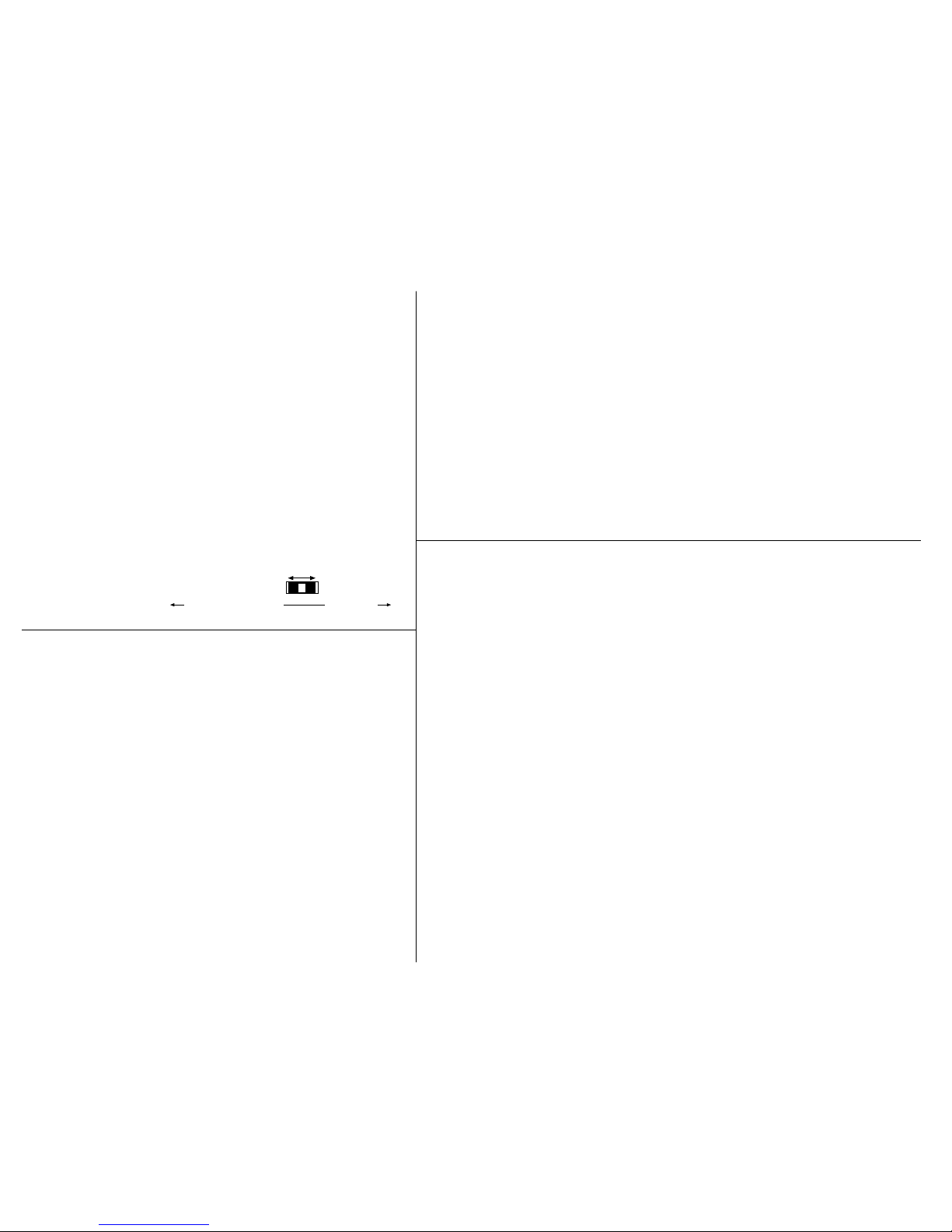
A Coax configuration switch sets an internal 10BASE-2
terminator to EITHER 50 ohms OR 0 ohms.
• 0 ohm switch position is used when connecting to the
middle or in line of a thin coax segment.
• 50 ohm switch position is used when connecting end of
coax segment DIRECTLY to the media converter's BNC
port.
C/E-CX-TBT-04
100BASE-TX
Copper
Ethernet
TM
C/E-CX-TBT-04
10BASE2
10BASE-T
10BASE-2
Coaxial Cable
C/E-CX-TBT-04
Provides an RJ-45 connector to
unshielded twisted pair 10BASE-T cable
and a coax connector to 10BASE-2
coaxial “thin-net” Ethernet™ cable.
Ethernet
TM
C/E-CX-TBT-04
10BASE2
10BASE-T
Straight-through Cable Configuration
Straight-through/crossover 10BASE-T requirements are satisfied using the
MDI/MDI-X switch with straight-through cable.
The two active pairs in a 10BASE-T
network are pins 1 & 2 and pins 3 & 6.
Use only dedicated wire pairs (such as
blue/white & white/blue, orange/white &
white/orange) for the active pins.
1
2
3
6
Twisted
Pair #1
Twisted
Pair #2
Straight Through Cable
1
2
3
6
Status LEDs
Coax Switch
L(in)K Steady green LED indicates port is receiving link
signal.
RX (Receive) Flashing green LED indicates port is
receiving data.
P(o)w(e)r Steady green LED indicates connection to external
AC power.
Jab(ber) Steady green LED indicates a jabber condition.
Coll(ision) Flashing green LED indicates port is in a collision
state. NOTE: Steady illumination indicates an
excessive number of collisions are occurring on
the port.
Page 2
1. Is the power LED on the media converter illuminated?
NO
• Is the Slide-In-Module properly connected to the Media Conversion Center chasis
backplane?
• Is the Power Supply Module properly connected both to the Media Conversion Center
chasis backplane and to the AC outlet?
• Contact Technical Support at (800) 260-1312/ (800) LAN-WANS.
YES
• Proceed to step 2.
2. Is the 10BASE-2 link able to receive signals?
NO
• Check coax cables for proper connection.
• Check coax cable for opens or shorts. Check and/or replace each BNC “T” connector
on the segment, making sure each “T” is attached firmly.
• Verify that coax cables on media converter are terminated properly at both ends.
NOTE: In a coax thinnet installation, the first and last device in a daisy-chain are
terminated.
• Verify that each 10BASE-2 segment is grounded to earth ground.
• Contact Technical Support at (800) 260-1312/ (800) LAN-WANS.
YES
• Proceed to step 3.
3. Is the 10BASE-T Link LED illuminated?
NO
• Check copper cables for proper connection.
• Be certain that the 10BASE-T cable is configured correctly for site installation (straight
through or crossover)
• Contact Technical Support at (800) 260-1312/ (800) LAN-WANS.
YES
• Contact Technical Support at (800) 260-1312/ (800) LAN-WANS.
Troubleshooting
The physical characteristics of the media cable must meet or exceed IEEE
802.3 10BASE-T and 10BASE-CX specifications.
ETHERNET CABLE SPECIFICATIONS
10BASE-T CABLE SPECIFICATIONS
Category 3 wire or better is required; category 5 wire is recommended. Shielded twisted pair
(STP) or unshielded twisted pair (UTP) can be used. DO NOT USE FLAT OR SILVER SATIN
WIRE.
Category 3:
Gauge 24 to 22 AWG
Attenuation 28 dB/1000’ @ 10 MHz
Differential Characteristic Impedance 100 Ω ±10% @ 10 MHz
Category 5:
Gauge 24 to 22 AWG
Attenuation 20 dB/1000’ @ 10 MHz
Differential Characteristic Impedance 100 Ω ±10% @ 10 MHz
Maximum Cable Distance: 100 meters (330 feet)
10BASE-2 CABLE SPECIFICATIONS
Cable type: Stranded Coaxial RG58
Impedance: 50 Ω @ 10 MHz
Mutual Capacitance: 24 pF/ft ±20% @ 10 MHz
Maximum Cable Distance: 185 meters (610 feet)
Maximum number connections:30
Minimum distance/connection: 0.5 meters (1.6 feet)
Installing Slide-In-Module(s)
CAUTION: Wear a grounding device and observe electrostatic discharge precautions when
installing Media Converter Slide-in-Module(s) in the 16-Slot Media Conversion Center. Failure to
observe this caution could result in damage to, and subsequent failure of, the Media Converter
Slide-in-Module(s).
NOTE: Media Converter Slide-in-Modules can be installed in any installation slot, in any order.
To install the Media Converter Slide-in-Module in the E-MCC-1600 chassis:
1. Remove Media Converter Slide-in-Module protective plate from selected installation slot by
removing two screws that secure plate to front of E-MCC-1600. Retain one installation screw.
2. Carefully slide Media Converter Slide-in-Module into installation slot, aligning Media Converter
Slide-in-Module with installation guides.
NOTE: Ensure that the Media Converter Slide-in-Module is firmly seated against the backplane.
3. Secure Slide-in-Module by installing retained installation screw.
10BASE-2 CABLE CONNECTIONS
• Ground EACH coax segment to earth ground at one end.
• Set coax configuration switch:
Use 50 ohm switch position when connecting the end of a coax
segment DIRECTLY to the media converter's BNC port.
Use 0 ohm switch position when connecting to the middle or in line of
a thin coax segment. (For this position a BNC "T" must be connected
to the media converter's BNC port).
10BASE-T CABLE CONNECTIONS
• Be certain that the MDI/MDI-X switch located ON the Slide-In-Module
circuit board is set correctly BEFORE INSTALLING SLIDE-IN-MODULE
IN MEDIA CONVERSION CENTER. Cable connections between a hub
and the media converter require the MDI/MDI-X switch to be set to
MDI. Cable connections between the media converter and a terminal,
transceiver or NIC require the switch to be set to MDI-X.
• Using small flatblade screwdriver or
similar tool, set MDI/MDI-X switch
position for site installation.
MDI
position
MDI-X
position
toward network connectors toward chassis
C/E-CX-TBT-04
 Loading...