

Page 1

TS-ABX31
Intel Socket 370 Celeron Series
USER/S MANUAL
Transcend
Your Supplier, Your Partner,
Your Friend.
Page 2

User/s Notice
This User/s Manual is designed to assist system manufacturers or end users
to set up and install the motherboard. All information within this document has
been carefully checked. However, Transcend Information, Inc. (hereinafter referred to as “Transcend”) carries no responsibility on liability to any error or
inaccuracy which might occur in this manual, including the products and software mentioned in it. In addition, the information and specifications are subject
to change without notice in advance.
Transcend Information, Inc. provides this manual “as is” without warranty of
any kind, either expressed or implied, including but not limited to the implied
warranties, conditions of merchantability or fitness for a particular purpose. In
no event shall Transcend Information, Inc., its employers, employees, distributors, or agents be liable for any indirect, special, incidental, or consequential
damages, including loss of profits, loss of business, loss of use or data, interruption of business and the like, even if Transcend Information, Inc. has been
advised of the possibility of such damages arising from any defect or error in
this manual or product.
All brands, product names, and trademarks mentioned in this document are
the property of their respective owners or companies and are used only for
identification or explanation.
Product Model: TS-ABX31
Manual Version: 1.1
Release Date: November,1999
Page 3

Table of Contents
CHAPTER 1 INTRODUCTION 1
1.1 Package Contents ............................................................................................................ 1
1.2 Specifications and Features ........................................................................................... 1
CHAPTER 2 HARDWARE INSTALLATION 3
2.1 Transcend TS-ABX31 Motherboard .................................................................... 3
2.2 Layout of Transcend TS-ABX31 Motherboard................................................. 4
2.3 CPU Installation ............................................................................................ 5
2.4 66/100MHz System Configuration........................................................ 6
2.5 CPU Internal Frequency Ratio Setting............................................................ 6
2.6 Memory Configuration ................................................................................... 8
2.7 Keyboard Wake Up ....................................................................................... 9
2.8 Primary / Secondary IDE Connectors ............................................................. 9
2.9 Floppy Disk Drive Connector .......................................................................... 10
2.10 Fan Power Connectors .................................................................................. 10
2.11 Wake-on-LAN Connector ............................................................................ 11
2.12 IrDA-Compliant Infrared Module Connector .................................................. 11
2.13 Panel Connectors....................................................................................... 12
2.14 Power Connector....................................................................................... 13
2.15 External Connectors....................................................................................14
2.16 Clear CMOS Jumper................................................................................... 15
Page 4

CHAPTER 3 BIOS SETUP 16
3.1 BIOS Setup ....................................................................................................................... 16
3.2 The Main Menu ................................................................................................................ 16
3.3 Standard CMOS Setup ................................................................................................... 18
3.4 BIOS Features Setup ...................................................................................................... 21
3.5 Chipset Features Setup .................................................................................................. 24
3.6 Power Management Setup ............................................................................................ 27
3.7 PnP/PCI Configuration Setup.......................................................................................... 30
3.8 Integrated Peripherals ................................................................................................... 32
3.9 Supervisor Password ..................................................................................................... 35
3.10 User Password ............................................................................................................. 36
3.1 1 IDE HDD Auto Detection ............................................................................................. 36
3.12 Save & Exit Setup ......................................................................................................... 37
3.13 Exit Without Saving ...................................................................................................... 37
3.14 Load BIOS Defaults ...................................................................................................... 38
3.15 Load Setup Defaults ..................................................................................................... 38
CHAPTER 4 BIOS UPGRADE 39
4.1 How to Check Y our BIOS File Name and V ersion ....................................................... 39
4.2 Download Correct BIOS File from Web....................................................................... 39
4.3 How to Update Y our Motherboard BIOS ...................................................................... 39
Page 5

1
INTRODUCTION
CHAPTER 1 INTRODUCTION
1.1 Package Contents
This motherboard package contains the following items. If you discover any damaged or missing
items, please contact your retailer.
1 - TS-ABX31 motherboard
2 - CD-ROM
3 - One FDD cable, one IDE cable
4 - User’s Manual
1.2 Specifications and Features
• •
• CPU
• •
- Support Intel Socket 370 Celeron Series
• •
• Chipset
• •
- Intel 440BX AGP
• •
• DRAM Memory
• •
- Support Synchronous DRAM
- 3pcs of 168-pin DIMM module sockets on board
- 8~768 MB memory size
- 8/16/32/64/128/256MB SDRAM DIMM
- 64 data bits and ECC structure.
• •
• I/O BUS Slot
• •
- 1 AGP slot
- 4 Master / Slave PCI-BUS slots (PCI 2.1 compliant)
- 2 ISA BUS slots (one PCI/ISA shared)
• •
• I/O Functions
• •
- Support PIO Mode 3,4 A T API devices and Ultra DMA/33
- Support 2 high speed UART 16550 COM Ports
- Support EPP/ECP LPT Port
- Support 1.44/2.88 MB floppy drive
Page 6

INTRODUCTION
- Support PS/2 mouse and PS/2 keyboard
- Support IrDA port
- Support 2 Universal Serial Bus Ports
•
Award BIOS
- Support Plug-and-Play
- Support ACPI, DMI, Green Feature
•
Wake Up Features
- PS/2 mouse and keyboard Wake Up
- Support Wake-on-LAN function
- Remote Ring Wake Up
•
PCB Dimensions
- A TX form factor , 4-layer PCB, 17.3cm x 30.5cm (6.8inch x 12inch)
2
Page 7
3
Intel 440BX
HARDW ARE INST ALLA TION
CHAPTER 2 HARDWARE INSTALLATION
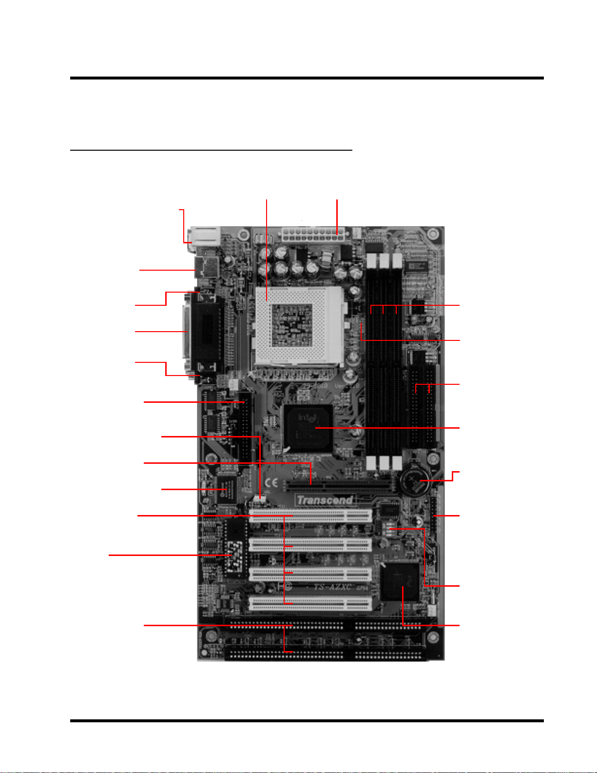
2.1 Transcend TS-ABX31 Motherboard
* T:PS/2 Mouse
**B:PS/2 Keyboard
* T:USB1
**B:USB2
**B:COMB
*T:Parallel
(Printer)
**B:COMA
Floppy Driver
Connector
Walk On LAN
Socket 370
CPU
ATX Power
Connector
3 DIMM
Sockets
66/100MHz
2 IDE
Connectors
ChipSet
AGP Port
Multi I/O Chip
4 PCI Slots
BIOS
2 ISA Slots
*T:Top
**B:Bottom
LI Battery
Panel
Connector
CPU
Freq-Ratio
DIP Switch
Intel PIIX4
ChipSet
Page 8
HARDW ARE INST ALLA TION
n
(
(
(
(
o
o
AGP Se
y
l
X
C
C
y
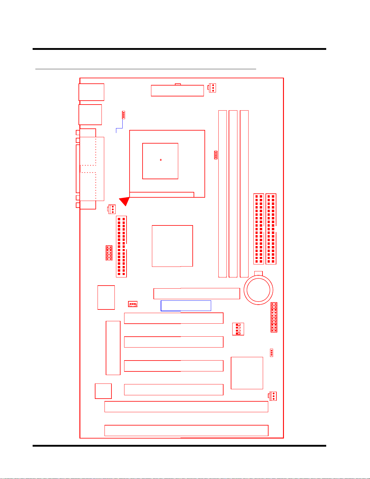
2.2 Layout of Transcend TS-ABX31 Motherboard
4
KB MOUSE
PS/2
T:Mouse
board
B:Ke
USB
USB
T:Port 1
B:Port 2
COMB
COMB
Printer
Parallel Port
COMA
COMA
Keyboard
Controller
CPU-FAN
IrDA
ared Port
Infr
Multi-I/O
&
JP1
KB-AWK
Pin1
FDC
Drive Connector
Floppy
Wake-on-LAN
WOL
PCI1
PCI Slot1
ONN
PWR-
ATX Power
Socket 37
Thermal
Sensor
onnector
0
Inte
440B
AGP Slot
Tra
scend
PCI1)
AGP
POWER-FAN
66/100MHz
PGA 370
JP2
DIMM2 (64bit or ECC168pin SDRAM Module)
DIMM1 (64bit or ECC 168pin SDRAM Module)
DIMM2 (64bit or ECC 168pin SDRAM Module)
Secondary IDE Connector
IDE2
Li
Batter
SW1
Primary IDE Connector
IDE
1
BAT1
PCI2
PCI Slot2
PCI3
PCI Slot3
2Mbit Flash (BIOS)
Hardware
Monitor
PCI4
PCI Slot4
ISA1
ISA Sl
ISA2
ISA Sl
PCI2)
PCI3)
PCI4)
t1 (ISA1)
t2 (ISA2)
Intel
PIIX4
ChipSet
DIP Switch
CPU Freg.-Ratio
Panel Connector
JP4
CMOS_CLR
CASE-FAN
Page 9
5
HARDW ARE INST ALLA TION
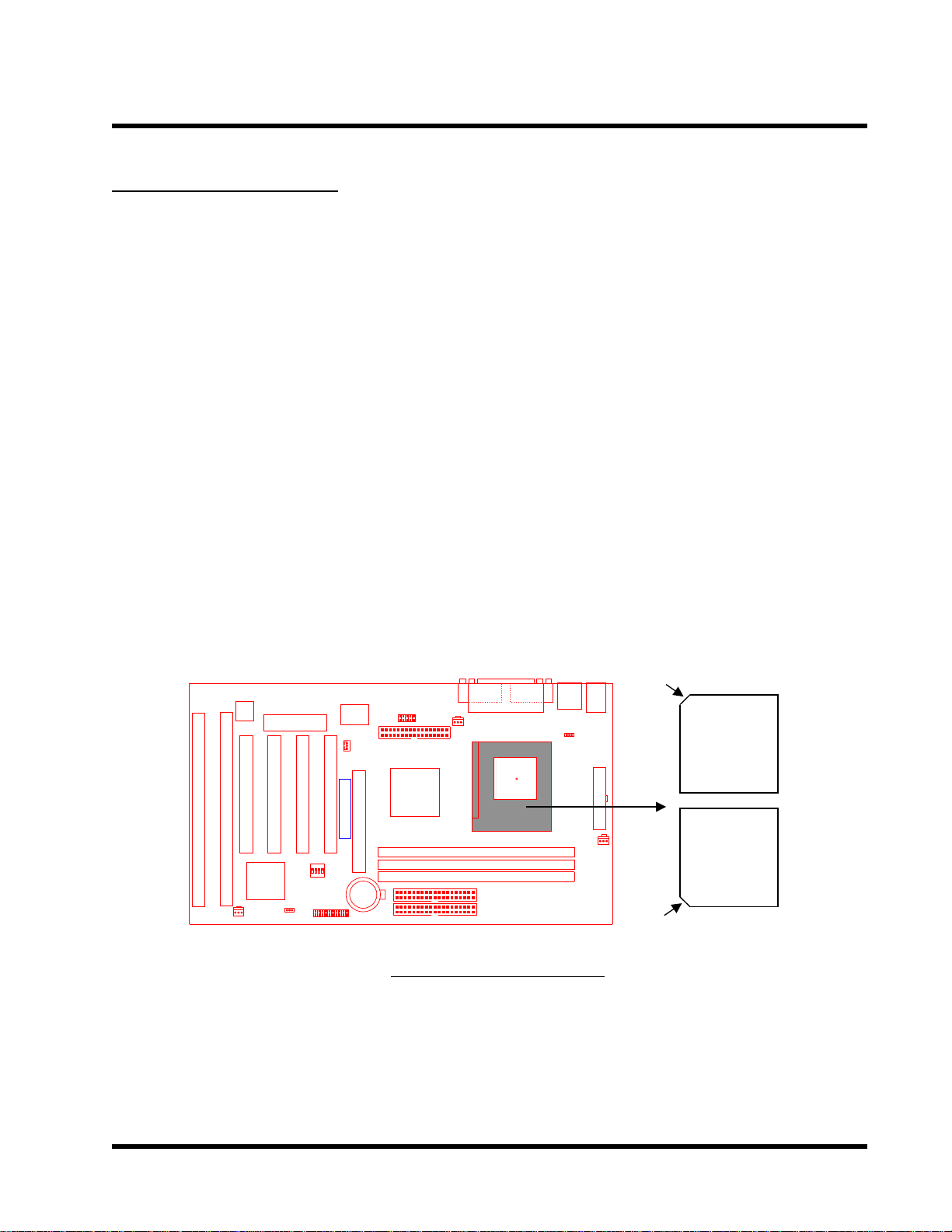
2.3 CPU Installation
The motherboard provides a ZIF Socket 370. The CPU that you bought must have a fan attached
to it to prevent overheating. If there is no fan on it, please purchase a fan before you turn on your
system.
W ARNING! Be sure that sufficient air circulation is available across the processor’s passive heatsink. Without sufficient circulation, the processor could overheat and damage
both the processor and the motherboard. Y ou may install an auxiliary fan, if necessary .
T o install a CPU, first turn off your system and remove its cover . Locate the ZIF socket and open
it by first pulling the lever sideways away from the socket then upwards to a 90-degree right
angle. Insert the CPU with the correct orientation as shown below. The picture below is for reference only . Y ou should have a CPU fan to cover the face of the CPU. With the added weight of the
CPU fan, no force is required to insert the CPU. Once completely inserted, close the socket/s
lever while holding down the CPU.
HardwareMonitor
ISA1
ISA2
PCI Slot4 (PCI4)
ISA Slot1 (ISA1)
ISA Slot2 (ISA2)
CASE-FAN
2Mbit Flash (BIOS)
PCI3
PCI4
PCI Slot2 (PCI2)
PCI Slot3 (PCI3)
IntelPIIX4ChipSet
CMOS_CLR
PANEL
PCI2
PCI Slot1 (PCI1)
FrequencyDIP Switch
Panel Switch
Multi-I/O&KeyboardController
Wake On LAN
WOL
PCI1
Transcend
AGP
Infrared Port
AGP
CR2032 3VLithium Cell
IDE1IDE2
COMA
IrDA
CPU-FAN
FDC
Floppy Connector
Intel443ZXAGP Set
Second IDE Connector
Primary IDE Connector
TS-ABX31
Printer
KB-AWK
Thermal Sensor
DIMM1 (64/72bit 168pin SDRAM Module)
DIMM2 (64/72bit 168pin SDRAM Module)
DIMM2 (64/72bit 168pin SDRAM Module)
Socket 370
Parallel Port
COM1
T:Mouse B:Keyboard
T:Port 1 B:Port 2
COM2
COMB
USB
Notch
PS/2
USB
KB MOUSE
Socket
370 CPU
(Top)
ATX Power Connector
POWER-FANPWR-CONN
Socket
370 CPU
(Bottom)
Notch
Page 10
HARDWARE INSTALLATION 6
ThermalSensor
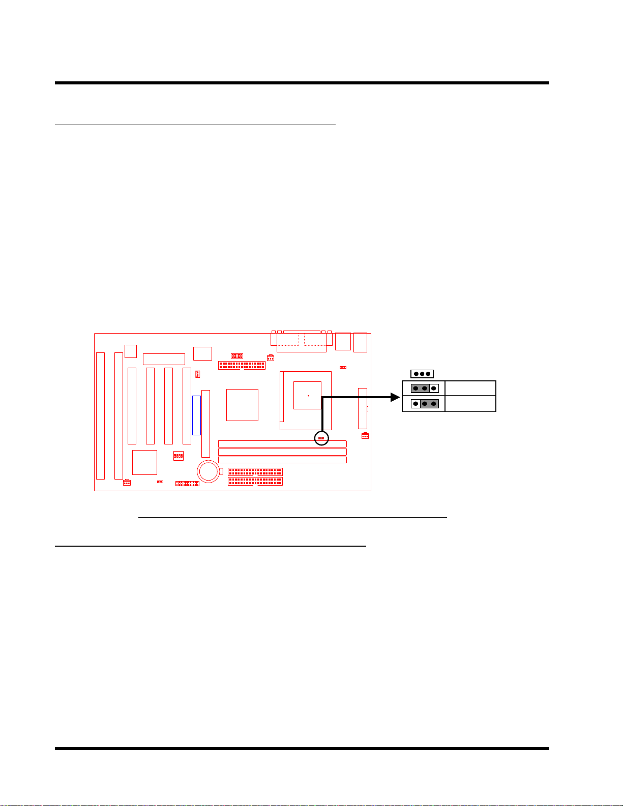
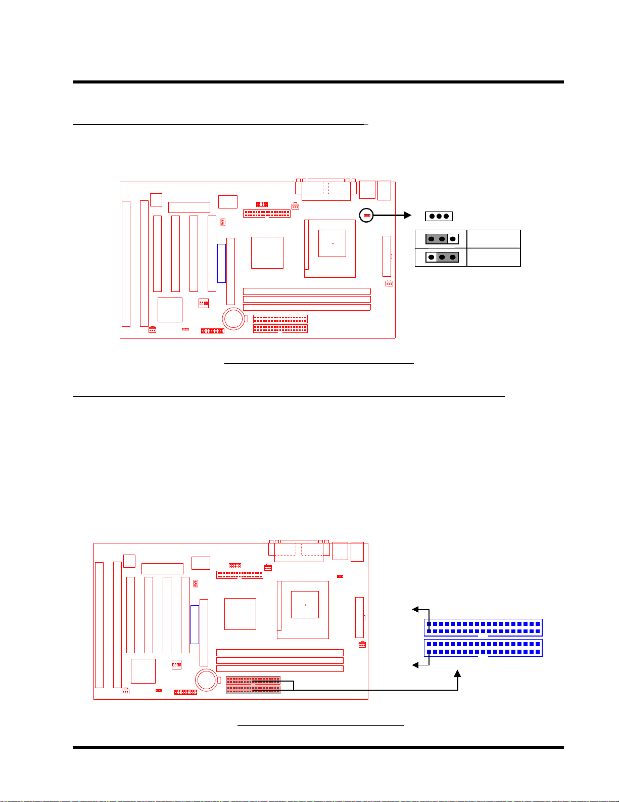
2.4 66/100MHz System Configuration
The jumper 2 (JP2) allows you to set FSB (Front Side Bus) to be 66 or 100MHz configuration.
When you set FSB to 66MHz, you can select the system bus frequency from 66MHz to 83.3MHz
through “CPU Host Clock (CPU/PCI)” of “Chipset Features Setup” in BIOS (Please refer to page
26). When you set FSB to 100MHz, you can select the system bus frequency from 100MHz to
150MHz through “CPU Host Clock (CPU/PCI)” of “Chipset Features Setup” in BIOS (Please
refer to page 26).
NOTE: Because Celeron socket 370 CPU now can support 66MHz FSB only , we strongly
recommend that you set JP2 as 66MHz. Otherwise it may cause system damaged. If
Intel releases new version Celeron CPU to support 100MHz FSB, then you can set JP2
as 100MHz to increase system performance.
HardwareMonitor
ISA1
ISA2
PCI Slot4 (PCI4)
ISA Slot1 (ISA1)
ISA Slot2 (ISA2)
CASE-FAN
2Mbit Flash (BIOS)
PCI3
PCI4
PCI Slot2 (PCI2)
PCI Slot3 (PCI3)
IntelPIIX4ChipSet
CMOS_CLR
PANEL
PCI2
PCI Slot1 (PCI1)
FrequencyDIP Switch
Panel Switch
Multi-I/O&KeyboardController
Wake On LAN
WOL
PCI1
Transcend
AGP
Infrared Port
AGP
CR2032 3VLithium Cell
IDE1IDE2
COMA
IrDA
FDC
Floppy Connector
Intel443ZXAGP Set
Second IDE Connector
Primary IDE Connector
TS-ABX31 66/100MHz FSB
Parallel Port
COM1
Printer
CPU-FAN
DIMM1 (64/72bit 168pin SDRAM Module)
DIMM2 (64/72bit 168pin SDRAM Module)
DIMM2 (64/72bit 168pin SDRAM Module)
KB-AWK
Thermal Sensor
T:Mouse B:Keyboard
T:Port 1 B:Port 2
COM2
COMB
USB
PS/2
USB
KB MOUSE
66/100MHz
66MHz
100MHz
ATX Power Connector
JP2
POWER-FANPWR-CONN
1
1
1
Configuration Jumper
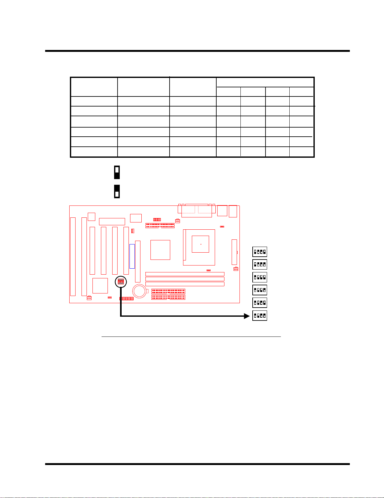
2.5 CPU Internal Frequency Ratio Setting
The switch 1 (SW1) is designated for adjusting the CPU internal frequency ratio. The frequency
ratio is defined as the table shown below. The internal frequency can be calculated by the following formula:
CPU internal frequency = frequency ratio x system bus frequency *
* System bus frequency is set in “CPU Host Clock (CPU/PCI)” of “Chipset Features Setup” in
BIOS (Please refer to page 26).
NOTE: Because Intel has locked the Socket 370 Celeron CPU’s frequency ratio, setting
SW1 to adjust the frequency ratio is useless. Howerer, it may be effective if Intel unlocks
the frequency ratio in the future.
Page 11
7
D
g
r
HARDW ARE INST ALLA TION
CPU Internal
Frequency
333/500MHz
366/550MHz
400/600MHz
433/650MHz
466/700MHz
500/750MHz
O: ON
X: OFF
HardwareMonitor
PCI4
ISA1
ISA2
PCI Slot4 (PCI4)
ISA Slot1 (ISA1)
ISA Slot2 (ISA2)
CASE-FAN
SW1
1
ON
ON
OFF
OFF
OFF
OFF
T:Mouse B:Keyboard
T:Port 1 B:Port 2
COM2
COMB
USB
USB
KB-AWK
IrDA
Floppy Connector
Intel443ZXAGP Set
Second IDE Connector
Primary IDE Connector
Freq.-Ratio
x 5.0
x 5.5
x 6.0
x 6.5
x 7.0
x 7.5
COMA
CPU-FAN
FDC
DIMM1 (64/72bit 168pin SDRAM Module)
DIMM2 (64/72bit 168pin SDRAM Module)
DIMM2 (64/72bit 168pin SDRAM Module)
Printer
Printer
Parallel
allel Port
COM1
IP Switch
Thermal Sensor
JP2
66/100MHz
66/100MHz
66/100MHz
66/100MHz
66/100MHz
66/100MHz
Infrared Port
AGP
CR2032 3VLithium Cell
IDE1IDE2
PCI2
PCI Slot1 (PCI1)
FrequencyDIP Switch
Panel Switch
Multi-I/O&KeyboardController
Wake On LAN
WOL
PCI1
Transcend
AGP
2Mbit Flash (BIOS)
PCI3
PCI Slot2 (PCI2)
PCI Slot3 (PCI3)
IntelPIIX4ChipSet
CMOS_CLR
PANEL
CPU Freq.-Ratio
2
OFF
OFF
ON
ON
ON
ON
PS/2
KB MOUSE
3
OFF
OFF
ON
ON
OFF
OFF
4
ON
OFF
ON
OFF
ON
OFF
SW1
ATX Power Connector
ON DIP
: 333/500MHz
1 2 3 4
ON DIP
POWER-FANPWR-CONN
: 366/550MHz
1 2 3 4
ON DIP
: 400/600MHz
1 2 3 4
ON DIP
: 433/650MHz
1 2 3 4
ON DIP
: 466/700MHz
1 2 3 4
ON DIP
: 500/750MHz
1 2 3 4
TS-ABX31 CPU Freq.-Ra
tio DIP Switch Settin
Page 12
HARDWARE INSTALLATION 8
n
P
M
M
M
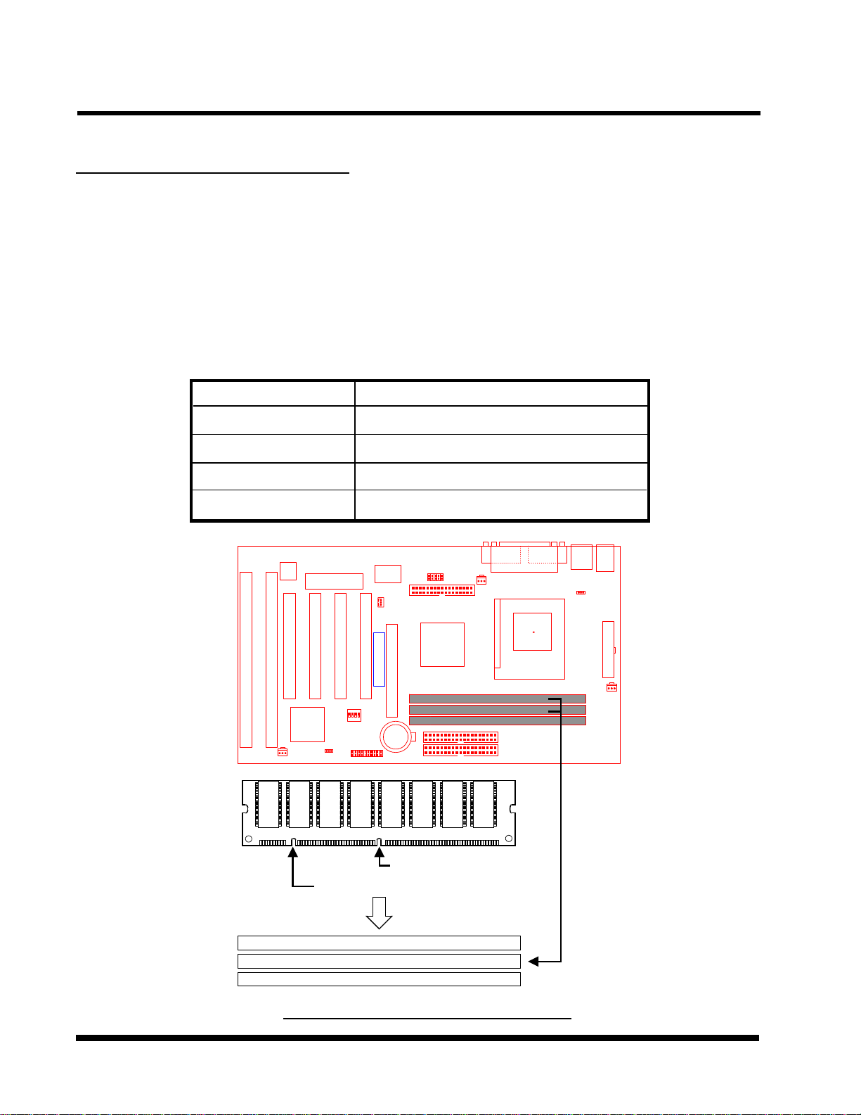
2.6 Memory Configuration
This motherboard must be installed with DIMM (Dual Inline Memory Module). The DIMMs must
be 3.3 V olt synchronous DRAM modules. It also supports ECC (Error Checking and Correcting).
IMPORTANT: Memory speed setup is required through “Auto Configuration“ in BIOS
Chipset Features Setup.
Install memory in any combination as follows:
DIMM Location
DIMM1
DIMM2
DIMM3
T otal Memory
HardwareMonitor
PCI3
PCI4
ISA1
ISA2
PCI Slot4 (PCI4)
ISA Slot1 (ISA1)
ISA Slot2 (ISA2)
PCI Slot3 (PCI3)
IntelPIIX4ChipSet
CASE-FAN
168-pin DIMM
SDRAM 8,16, 32, 64,128 ,256MBytes
SDRAM 8,16, 32, 64,128, 256MBytes
SDRAM 8,16, 32, 64,128, 256MBytes
768MBytes (MAX.)
Infrared Port
AGP
CR2032 3VLithium Cell
IDE1IDE2
PCI2
PCI Slot1 (PCI1)
FrequencyDIP Switch
Panel Switch
Multi-I/O&KeyboardController
Wake On LAN
WOL
PCI1
Transcend
AGP
2Mbit Flash (BIOS)
PCI Slot2 (PCI2)
CMOS_CLR
PANEL
COMA
IrDA
FDC
Floppy Connector
Intel443ZXAGP Set
Second IDE Connector
Primary IDE Connector
Printer
CPU-FAN
Parallel Port
COM1
T:Port 1 B:Port 2
COM2
COMB
USB
KB-AWK
Thermal Sensor
T:Mouse B:Keyboard
PS/2
USB
KB MOUSE
PWR-CONN
ATX Power Connector
POWER-FAN
osition
3.3V
Unbuffered Positio
168Pin SDRAM Module (DI
168Pin SDRAM Module (DI
168Pin SDRAM Module (DI
TS-ABX31 168Pi
n
MM1)
MM2)
MM3)
n DIMM Sockets
Page 13
9 HARDWARE INSTALLATION
E
yb
W
y
2.7 Keyboard Wake Up (3-pin KB-AWK)
This function disables or enables you to use the keyboard to power up the system. Set this
jumper to “Enable” if you wish to use your keyboard to power up your computer .
HardwareMonitor
ISA1
ISA2
PCI Slot4 (PCI4)
ISA Slot1 (ISA1)
ISA Slot2 (ISA2)
CASE-FAN
2Mbit Flash (BIOS)
PCI3
PCI4
PCI Slot2 (PCI2)
PCI Slot3 (PCI3)
IntelPIIX4ChipSet
CMOS_CLR
PANEL
PCI2
PCI Slot1 (PCI1)
FrequencyDIP Switch
Panel Switch
Multi-I/O&KeyboardController
Wake On LAN
WOL
PCI1
Transcend
AGP
Infrared Port
AGP
CR2032 3VLithium Cell
IDE1IDE2
COMA
IrDA
FDC
Floppy Connector
Intel443ZXAGP Set
Second IDE Connector
Primary IDE Connector
Printer
CPU-FAN
DIMM1 (64/72bit 168pin SDRAM Module)
DIMM2 (64/72bit 168pin SDRAM Module)
DIMM2 (64/72bit 168pin SDRAM Module)
Parallel Port
COM1
T:Port 1 B:Port 2
T:Mouse B:Keyboard
COM2
COMB
USB
PS/2
USB
KB MOUSE
KB-AWK
Thermal Sensor
ATX Power Connector
POWER-FANPWR-CONN
1
1
1
JP1
KB-AWK
Disable
Enable
TS-ABX31 Ke
oard Wake Up
2.8 Primary / Secondary IDE Connectors (T wo 40-pin IDE)
This motherboard supports two 40-pin IDE connectors marked as IDE1(primary channel) and
IDE2 (secondary channel). Each channel supports two IDE devices that make total of four devices. In order to work together , two devices on each channel must be set differently to master
and slave mode, either one can be hard disk or CDROM. The setting as master or slave mode
depends on the jumper on your IDE devices. Please refer to their manual accordingly . Connect
your first IDE hard disk to master mode of the primary channel.
HardwareMonitor
ISA1
ISA2
PCI Slot4 (PCI4)
ISA Slot1 (ISA1)
ISA Slot2 (ISA2)
CASE-FAN
2Mbit Flash (BIOS)
PCI3
PCI4
PCI Slot2 (PCI2)
PCI Slot3 (PCI3)
IntelPIIX4ChipSet
CMOS_CLR
PANEL
PCI2
PCI Slot1 (PCI1)
FrequencyDIP Switch
Panel Switch
Multi-I/O&KeyboardController
Wake On LAN
WOL
PCI1
Transcend
AGP
Infrared Port
AGP
CR2032 3VLithium Cell
IDE1IDE2
COMA
IrDA
FDC
Floppy Connector
Intel443ZXAGP Set
Second IDE Connector
Primary IDE Connector
Printer
KB-AWK
CPU-FAN
DIMM1 (64/72bit 168pin SDRAM Module)
DIMM2 (64/72bit 168pin SDRAM Module)
DIMM2 (64/72bit 168pin SDRAM Module)
K
Thermal Sensor
Parallel Port
COM1
T:Mouse B:Keyboard
T:Port 1 B:Port 2
COM2
COMB
USB
PS/2
USB
KB MOUSE
IDE
ATX Power Connector
PIN1
POWER-FANPWR-CONN
PIN1
Secondar
IDE1IDE2
Primary IDE Connector
IDE Connector
TS-ABX31 ID
Connectors
Page 14
HARDWARE INSTALLATION 10
P
O
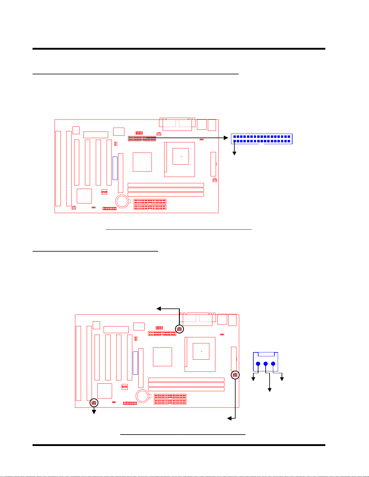
2.9 Floppy Disk Drive Connector (34-pin FDC)
This connector supports the provided floppy disk drive ribbon cable. After connecting the single
end to the board, connect the two plugs on the other end to the floppy drives.
HardwareMonitor
ISA1
ISA2
PCI Slot4 (PCI4)
ISA Slot1 (ISA1)
ISA Slot2 (ISA2)
CASE-FAN
2Mbit Flash (BIOS)
PCI3
PCI4
PCI Slot2 (PCI2)
PCI Slot3 (PCI3)
IntelPIIX4ChipSet
CMOS_CLR
PANEL
PCI2
PCI Slot1 (PCI1)
FrequencyDIP Switch
Panel Switch
Multi-I/O&KeyboardController
Wake On LAN
WOL
PCI1
Transcend
AGP
Infrared Port
AGP
CR2032 3VLithium Cell
IDE1IDE2
COMA
IrDA
CPU-FAN
FDC
Floppy Connector
Intel443ZXAGP Set
Second IDE Connector
Primary IDE Connector
TS-ABX31 Floppy Di
Printer
KB-AWK
Thermal Sensor
DIMM1 (64/72bit 168pin SDRAM Module)
DIMM2 (64/72bit 168pin SDRAM Module)
DIMM2 (64/72bit 168pin SDRAM Module)
sk Drive Connector
Parallel Port
COM1
T:Mouse B:Keyboard
T:Port 1 B:Port 2
COM2
COMB
USB
PS/2
USB
KB MOUSE
Floppy Drive Connector
PIN1
ATX Power Connector
POWER-FANPWR-CONN
FDC
2.10 Fan Power Connectors
There are three fan power connectors on the motherboard: CPU _FAN, POWER_FAN, and
CASE_F AN. Each connector provides +12V power. Make sure it is in the right orientation, or it
may cause damages. These connectors support cooling fans of 500 mA (6W) or less.
HardwareMonitor
PCI4
ISA1
ISA2
PCI Slot4 (PCI4)
ISA Slot1 (ISA1)
ISA Slot2 (ISA2)
PCI Slot3 (PCI3)
IntelPIIX4ChipSet
CASE_FAN
CPU_FAN
Infrared Port
Floppy Connector
Intel443ZXAGP Set
AGP
CR2032 3VLithium Cell
IDE1IDE2
PCI2
PCI Slot1 (PCI1)
FrequencyDIP Switch
Panel Switch
Multi-I/O&KeyboardController
Wake On LAN
WOL
PCI1
Transcend
AGP
2Mbit Flash (BIOS)
PCI3
PCI Slot2 (PCI2)
CMOS_CLR
PANEL
TS-ABX31 Fan
COM1
COMA
IrDA
CP
U-FAN
FDC
DIMM1 (64/72bit 168pin SDRAM Module)
DIMM2 (64/72bit 168pin SDRAM Module)
DIMM2 (64/72bit 168pin SDRAM Module)
Second IDE Connector
Primary IDE Connector
P
WER_FAN
ower Connectors
Parallel Port
Printer
KB-AWK
Thermal Sensor
T:Mouse B:Keyboard
T:Port 1 B:Port 2
COM2
COMB
USB
PS/2
USB
KB MOUSE
FAN
PWR-CONN
ATX Power Connector
POWER-FAN
Rotation
GND
+12V
Page 15

11 HARDWARE INSTALLATION
o
A
2.11 Wake-on-LAN Connector (3-pin WOL)
This connector connects to LAN cards with a Wake-on-LAN output. The system can be powered
up when a wakeup packet or signal is received from the LAN card.
NOTE:This function requires that the Wake-on-LAN Power Up Control is set to “En-
abled” and that your system has an A TX power supply with at least 720mA +5V standby
power.
HardwareMonitor
ISA1
ISA2
PCI Slot4 (PCI4)
ISA Slot1 (ISA1)
ISA Slot2 (ISA2)
CASE-FAN
2Mbit Flash (BIOS)
PCI3
PCI4
PCI Slot2 (PCI2)
PCI Slot3 (PCI3)
IntelPIIX4ChipSet
CMOS_CLR
PANEL
PCI2
PCI Slot1 (PCI1)
FrequencyDIP Switch
Panel Switch
Multi-I/O&KeyboardController
Wake On LAN
WOL
PCI1
Transcend
AGP
Infrared Port
AGP
CR2032 3VLithium Cell
IDE1IDE2
COMA
IrDA
FDC
Floppy Connector
Intel443ZXAGP Set
Second IDE Connector
Primary IDE Connector
Printer
CPU-FAN
DIMM1 (64/72bit 168pin SDRAM Module)
DIMM2 (64/72bit 168pin SDRAM Module)
DIMM2 (64/72bit 168pin SDRAM Module)
KB-AWK
Thermal Sensor
Parallel Port
COM1
T:Mouse B:Keyboard
T:Port 1 B:Port 2
COM2
COMB
USB
PS/2
USB
KB MOUSE
WOL
+5 Volt Standby
Ground
PME
ATX Power Connector
POWER-FANPWR-CONN
TS-ABX31 Wake-
n-LAN Connector
2.12 IrDA-Compliant Infrared Module Connector (5-pin IrDA)
The IrDA connector can be configured to support wireless infrared module. With this module and
application software such as Laplink or Win95 Direct Cable Connection, user can transfer files
to or from laptops, notebooks, PDA and printers.
HardwareMonitor
ISA1
ISA2
PCI Slot4 (PCI4)
ISA Slot1 (ISA1)
ISA Slot2 (ISA2)
CASE-FAN
2Mbit Flash (BIOS)
PCI3
PCI4
PCI Slot2 (PCI2)
PCI Slot3 (PCI3)
IntelPIIX4ChipSet
CMOS_CLR
PANEL
PCI2
PCI Slot1 (PCI1)
FrequencyDIP Switch
Panel Switch
Multi-I/O&KeyboardController
Wake On LAN
WOL
PCI1
Transcend
AGP
Infrared Port
AGP
CR2032 3VLithium Cell
IDE1IDE2
COMA
IrDA
FDC
Floppy Connector
Intel443ZXAGP Set
Second IDE Connector
Primary IDE Connector
TS-ABX31 IrD
Printer
CPU-FAN
Thermal Sensor
PGA 370
DIMM1 (64/72bit 168pin SDRAM Module)
DIMM2 (64/72bit 168pin SDRAM Module)
DIMM2 (64/72bit 168pin SDRAM Module)
Connector
KB-AWK
Socket 370
Parallel Port
COM1
T:Mouse B:Keyboard
T:Port 1 B:Port 2
COM2
COMB
USB
PS/2
USB
KB MOUSE
IrDA
ATX Power Connector
15
POWER-FANPWR-CONN
+5V
NC
IRRX
IRTX
GND
Page 16

HARDWARE INSTALLATION 12
2.13 Panel Connectors
Power LED Lead (3-pin KEYLOCK)
This 3-pin connector attaches to the power LED.
Pin1 : +5V
Pin2 : NC
Pin3 : GND
Keylock Lead (2-pin KEYLOCK)
Use the keylock to enable or disable the keyboard.
Pin4 : KEYLOCK
Pin5 : GND
Speaker Lead (4-pin SPEAKER)
This 4-pin connector connects to the case-mounted speaker.
Pin7 : +5V
Pin8 : GND
Pin9 : NC
Pin10 : SPK
Suspend Mode LED Lead (2-pin S_LED)
The S_LED will light when the suspend mode works.
Pin1 1 : +5V
Pin12 : GND
Harddisk LED Lead (2-pin HDD_LED)
This 2-pin connector connects to LED of harddisk. The LED lights when a HDD is active.
Pin13 : +5V
Pin14 : GND
Suspend Switch Lead (2-pin SUS)
This allows the user to manually place the system into the suspend mode or “Green” mode where
system activities will be instantly decreased to save electricity and expand the life of certain
components when the system is not in use.
Pin15 & Pin16
Reset Switch Lead (2-pin RESET)
This 2-pin connector connects to the case-mounted reset switch for rebooting your computer
without having to turn off your power switch.
Pin17 & Pin18
Page 17

13 HARDWARE INSTALLATION
n
y
Software Power-Off Lead (2-pin SOFT_OFF)
Attach the SOFT_OFF Switch of the panel to this connector.
Pin19 & Pin20
HardwareMonitor
ISA1
ISA2
PCI Slot4 (PCI4)
ISA Slot1 (ISA1)
ISA Slot2 (ISA2)
CASE-FAN
2Mbit Flash (BIOS)
PCI3
PCI4
PCI Slot2 (PCI2)
PCI Slot3 (PCI3)
IntelPIIX4ChipSet
CMOS_CLR
PANEL
PCI2
PCI Slot1 (PCI1)
FrequencyDIP Switch
Panel Switch
Multi-I/O&KeyboardController
Wake On LAN
WOL
PCI1
Transcend
AGP
Infrared Port
AGP
CR2032 3VLithium Cell
IDE1IDE2
COMA
IrDA
FDC
Floppy Connector
Intel443ZXAGP Set
Second IDE Connector
Primary IDE Connector
Printer
CPU-FAN
DIMM1 (64/72bit 168pin SDRAM Module)
DIMM2 (64/72bit 168pin SDRAM Module)
DIMM2 (64/72bit 168pin SDRAM Module)
KB-AWK
Thermal Sensor
Parallel Port
COM1
TS-ABX31 Pa
T:Mouse B:Keyboard
T:Port 1 B:Port 2
COM2
COMB
USB
PS/2
USB
KB MOUSE
POWER LED
1
ATX Power Connector
POWER-FANPWR-CONN
++
+++
11
S_LED
el Connector
KEY LOCK
SUS
HDD_LED
SPEAKER
10
20
SOFT_OFF
RESET
2.14 Power Connector (20-pin PWR_CONN)
Make sure to plug the A TX power supply connector to the right direction. The pin definition is
shown below. Make sure that your A TX power supply can support at least 10mA on the standby
lead.
HardwareMonitor
ISA1
ISA2
PCI Slot4 (PCI4)
ISA Slot1 (ISA1)
ISA Slot2 (ISA2)
CASE-FAN
2Mbit Flash (BIOS)
PCI3
PCI4
PCI Slot2 (PCI2)
PCI Slot3 (PCI3)
IntelPIIX4ChipSet
CMOS_CLR
PANEL
PCI2
PCI Slot1 (PCI1)
FrequencyDIP Switch
Panel Switch
Multi-I/O&KeyboardController
Wake On LAN
WOL
PCI1
Transcend
AGP
Infrared Port
AGP
CR2032 3VLithium Cell
IDE1IDE2
COMA
IrDA
FDC
Floppy Connector
Intel443ZXAGP Set
Second IDE Connector
Primary IDE Connector
Printer
CPU-FAN
DIMM1 (64/72bit 168pin SDRAM Module)
DIMM2 (64/72bit 168pin SDRAM Module)
DIMM2 (64/72bit 168pin SDRAM Module)
Parallel Port
COM1
TS-ABX31 Pow
T:Port 1 B:Port 2
T:Mouse B:Keyboard
COM2
COMB
USB
PS/2
USB
KB MOUSE
KB-AWK
Thermal Sensor
+5.0V Standb
Power Good
PWR-CONN
POWER-FAN
er Connector
PWR-CONN
+12.0V
Ground
+5.0V
Ground
+5.0V
Ground
+3.3V
+3.3V
PSON# : Power Supply on
+5.0V
+5.0V
-5.0V
Ground
Ground
Ground
PSON#
Ground
-12.0V
+3.3V
Page 18

HARDWARE INSTALLATION 14
C
r
2.15 External Connectors
There are 5 kinds of external connectors on the motherboard.
1. PS/2 Mouse Connector (6-pin MOUSE)
The onboard PS/2 mouse connector is a 6-pin Mini-Din connector marked “MOUSE”
The view angle of drawing shown here is from back panel of the housing.
2. PS/2 Keyboard Connector (6-pin KB)
The onboard PS/2 keyboard connector is a 6-pin Mini-Din connector marked “KB”. The
view angle of drawing shown here is from back panel of the housing.
3. Universal Serial BUS USB Ports 1 & 2 (Two 4-pin USBs)
Y ou can attach USB devices to the USB connector . The motherboard contains two USB
connectors, which are marked as “USB”.
4. Parallel Port Connector (25-pin PRN)
The onboard printer connector is a 25-pin D-type connector marked “PRN”. The view
angle of drawing shown here is from back panel of the housing.
5. Serial Port Connectors (T wo 9-pin COMA/COMB)
The onboard serial connectors are 9-pin D-type connectors on the back panel of
motherboard. The serial port1 connector is marked as”COMA” and the serial port2
connector is marked as ”COMB”.
1. PS/2 Mouse
3. USB1
3. USB2
2. PS/2 Keyboard
4.
Parallel Port (Printer)
5.
OMB 5. COMA
TS-ABX31 Exte
rnal Connectors
Page 19

15 HARDWARE INSTALLATION
r
2.16 Clear CMOS Jumper (3-pin JP4)
T o clear the CMOS data, you should turn off your computer power and short the pin1 and pin2
of JP4.
HardwareMonitor
ISA1
ISA2
PCI Slot4 (PCI4)
ISA Slot1 (ISA1)
ISA Slot2 (ISA2)
CASE-FAN
2Mbit Flash (BIOS)
PCI3
PCI4
PCI Slot2 (PCI2)
PCI Slot3 (PCI3)
IntelPIIX4ChipSet
CMOS_CLR
PANEL
PCI2
PCI Slot1 (PCI1)
FrequencyDIP Switch
Panel Switch
Multi-I/O&KeyboardController
Wake On LAN
WOL
PCI1
Transcend
AGP
Infrared Port
AGP
CR2032 3VLithium Cell
IDE1IDE2
COMA
IrDA
CPU-FAN
FDC
Floppy Connector
Intel443ZXAGP Set
Second IDE Connector
Primary IDE Connector
DIMM1 (64/72bit 168pin SDRAM Module)
DIMM2 (64/72bit 168pin SDRAM Module)
DIMM2 (64/72bit 168pin SDRAM Module)
Printer
PGA 370
Parallel Port
COM1
TS-ABX31 Clea
T:Port 1 B:Port 2
T:Mouse B:Keyboard
COM2
COMB
USB
PS/2
USB
KB MOUSE
KB-AWK
Thermal Sensor
Socket 370
ATX Power Connector
POWER-FANPWR-CONN
1
1
1
CMOS Jumper
JP4
CMOS_CLR
CMOS_CLR
DEFAULT
Page 20
BIOS SETUP 16
CHAPTER 3 BIOS SETUP
3.1 BIOS Setup
Award BIOS has a built-in Setup program that allows users to modify the basic system configuration. This information is stored in CMOS RAM. So it can retain the Setup information when the
power is turned off. When the battery of CMOS fails, it will cause the data lost. When it happens,
you should set up your configuration parameters again after replacing the battery .
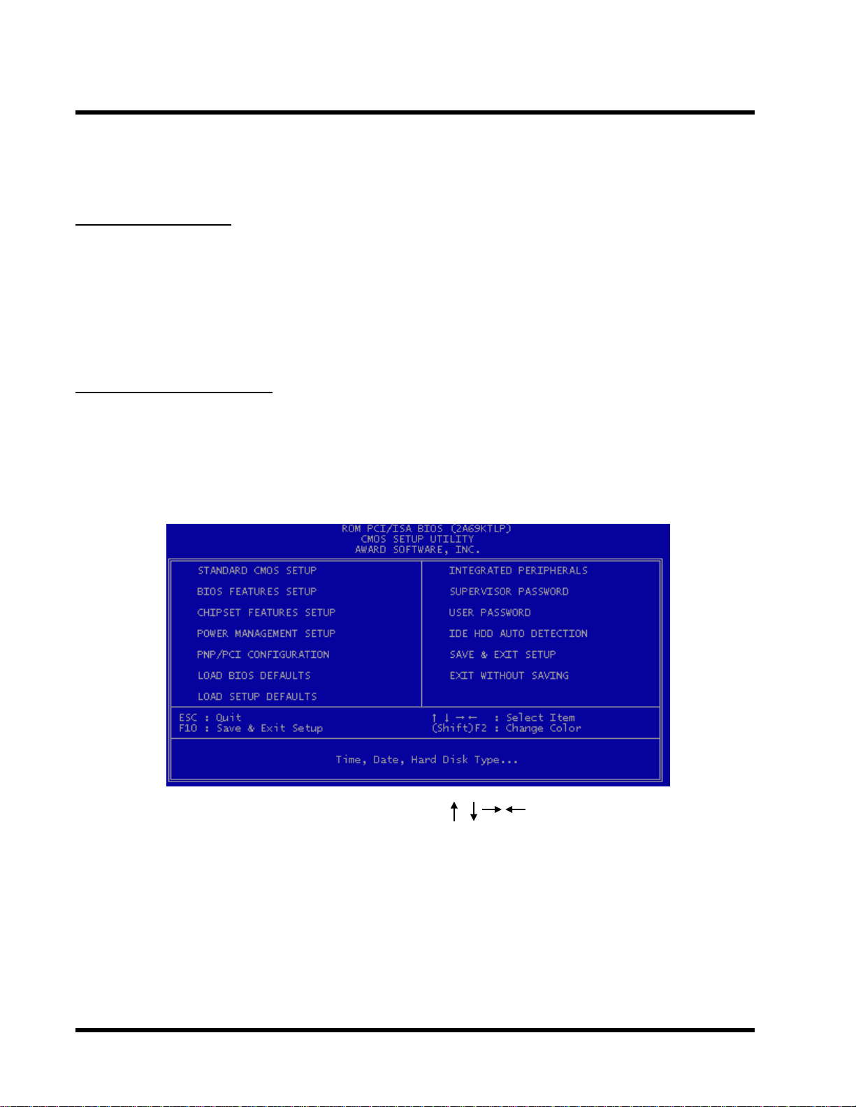
3.2 The Main Menu
As you turn on or reboot the system, the BIOS is immediately activated. It will read the system
configuration information, and check the system through Power On Self T est (POST). During the
POST process, press the [Del] key , and you can enter the Award BIOS configuration system. The
following screen will appear.
In the Award BIOS system, you can use the arrows (
the [Enter] key to enter the sub-menu. The following keys help you navigate in Setup.
Esc Main Menu: Quit and not save changes into CMOS RAM
Other pages: Exit current page and return to Main Menu
PgUp Increase the numeric value or make changes
PgDn Decrease the numeric value or make changes
+ Increase the numeric value or make changes
- Decrease the numeric value or make changes
) to highlight the item, and press
Page 21

17 BIOS SETUP
F1 General help, only for Status Page Setup Menu and Option Page Setup Menu
F2 Change color from total 16 colors
F2 to select color forward
Shift + F2 to select color backward
F3 Calendar, only for Status Page Setup Menu
F5 Restore the previous CMOS value from CMOS, only for Option Page Setup Menu
F6 Load the default CMOS RAM value from BIOS default table, only for Option Page
Setup Menu
F7 Load the default
F10 Save all the CMOS changes, only for Main Menu
The Following is a brief summary of each setup category .
• STANDARD CMOS SETUP
Options in the original PC A T-compatible BIOS
• BIOS FEATURES SETUP
Award enhanced BIOS options
• CHIPSET SETUP
Available options specific to your system Chipset
• POWER MANAGEMENT SETUP
Advanced Power Management (APM) options
• PnP/PCI CONFIGURATION
Plug and Play standard and PCI Local Bus configuration options
• LOAD BIOS DEFAULTS
BIOS defaults are factory settings for the most stable, minimal-performance system operations.
• LOAD SETUP DEFAULTS
Setup defaults are factory settings for optimal-performance system operations.
• INTEGRATED PERIPHERALS
I/O subsystems that depend on the integrated peripherals controller in your system
Page 22

BIOS SETUP 18
• SUPERVISOR / USER PASSWORD
Change, set, or disable a password. In some BIOS versions that allow separate user and
supervisor passwords, only the supervisor password permits access to Setup. The user password generally allows only power-on access.
• IDE HDD AUTO DETECTION
Automatically detect and configure IDE hard disk parameters.
• SAVE & EXIT SETUP
Save settings in nonvolatile CMOS RAM and exit Setup.
• EXIT WITHOUT SAVING
Abandon all changes and exit Setup.
3.3 Standard CMOS Setup
• Date (mm:dd:yy) / Time (hh:mm:ss)
Highlight the items and use PageUp/PageDown to change the value of Date/Time.
• Primary Master / Primary Slave / Secondary Master / Secondary Slave
This mainboard can support four IDE devices. We recommend that you select type “AUTO”
for all drives. The BIOS can automatically detect the specifications and optimal operating
mode of almost all IDE hard drives. When you select type “AUTO” for a hard drive, the BIOS
detects its specifications during POST while the system boots. If you do not want to select
drive type “AUTO”, other methods of selecting the drive type are also available.
Page 23

19 BIOS SETUP
1. Match the specifications of your installed IDE hard drive(s) with the preprogrammed values
for drive type 1 through 45.
2. Select “USER” and enter values into each drive parameter field.
3. Use the “IDE HDD AUTO DETECTION” function in Main Menu.
Here are the brief explanations of drive specifications.
* TYPE : The BIOS contains a table of pre-defined drive types. Each defined drive type
has a specified number of cylinders, number of heads, write precompensation factor,
landing zone, and number of sectors. Drives whose specifications do not accommodate any pre-defined type are classified as type “USER”.
* SIZE : Disk drive capacity (approximately). Note that this size is usually slightly greater
than the size of a formatted disk given by a disk-checking program.
* CYLS : Number of cylinders
* HEAD : Number of heads
* PRECOMP : Write precompensation cylinder
* LANDZ : Landing zone
* SECTOR : Number of sectors
* MODE : AUTO, NORMAL, LARGE, or LBA
- AUTO : The BIOS automatically determines the optimal mode.
- NORMAL : Maximum number of cylinders, heads, and sectors supported are 1024,
16, and 63 respectively .
- LARGE : For drives that do not support LBA and have more than 1024 cylinders.
- LBA (Logical Block Addressing) : During drive access, the IDE controller transforms
the data address described by sector, head, and cylinder number into a physical
block address. This will significantly improve data transfer rates for drives with
greater than 1024 cylinders.
Page 24

BIOS SETUP 20
•
Drive A / Drive B
Select the correct specifications for the diskette drive(s) installed in the computer .
- None : No diskette drive installed
- 360K, 5.25 in : 5-1/4 inch PC-type standard drive; 360 kilobyte capacity
- 1.2M, 5.25 in : 5-1/4 inch A T-type high-density drive; 1.2 megabyte capacity
- 720K, 3.5 in : 3-1/2 inch double-sided drive; 720 kilobyte capacity
- 1.44M, 3.5 in : 3-1/2 inch double-sided drive; 1.44 megabyte capacity
- 2.88M, 3.5 in : 3-1/2 inch double-sided drive; 2.88 megabyte capacity
•
Video
Select the type of primary video subsystem in your computer. The BIOS usually detects the
correct video type automatically . The BIOS supports a secondary video subsystem, but do
not select it in this Setup.
- EGA/VGA : Enhanced Graphics Adapter/Video Graphics Array . For EGA, VGA, SEGA,
SVGA or PGA monitor adapters.
- CGA 40 : Color Graphics Adapter, powers up in 40-column mode
- CGA 80 : Color Graphics Adapter, powers up in 80-column mode
- MONO : Monochrome adapter , includes high resolution monochrome adapters
•
Halt On
During the Power On Self T est (POST), the computer stops if the BIOS detects a hardware
error. You can set the BIOS to ignore certain errors during POST and continue the boot-up
process. The followings are the selections.
- No Errors : POST does not stop for any error.
- All Errors : If the BIOS detects any non-fatal error, POST stops and prompts you to take
corrective action.
- All, But Keyboard : If the BIOS detects any non-fatal error except keyboard, POST stops
and prompts you to take corrective action.
- All, But Diskette : If the BIOS detects any non-fatal error except floppy disk drive, POST
stops and prompts you to take corrective action.
- All, But Disk / Key : If the BIOS detects any non-fatal error except floppy disk drive or
keyboard, POST stops and prompts you to take corrective action.
Page 25

21 BIOS SETUP
3.4 BIOS Features Setup
This “BIOS FEA TURES SETUP” option allows you to improve your system performance and set
up system features according to your preference.
•
Virus Warning
When the function is enabled, you will receive a warning message if a program (specifically ,
a virus) attempts to write to the boot sector or the partition table of the hard disk drive. Y ou
should then run an anti-virus program. Keep in mind that this feature protects the boot sector
only , not the entire hard drive.
NOTE: Many disk diagnostic programs that access the boot sector table can trigger
the virus warning message. If you plan to run such a program, we recommend that
you first disable the virus warning.
• CPU Internal Cache / External Cache
Cache memory is additional memory that is much faster than conventional DRAM (system
memory). CPUs from 486-type or up contain internal cache memory . Most, but not all, modern PCs have additional (external) cache memory . When the CPU requests data, the system
transfers the requested data from the main DRAM into cache memory for even faster access
by the CPU. The External Cache field may not appear if your system does not have external
cache memory .
Page 26

BIOS SETUP 22
• CPU L2 Cache ECC Checking
Select “Enabled” to make sure the data accuracy .
• Quick Power On Self Test
Select “Enabled” to reduce the amount of time required to run the Power-On Self-T est (POST).
A quick POST skips certain steps. We recommend that you normally disable quick POST . It’s
better to find a problem during POST than to lose data during your work.
• Boot Sequence
The original IBM PCs load the DOS operating system from drive A (floppy disk). So, IBM PCcompatible systems are designed to search for an operating system first on drive A, and then
on drive C (hard disk). However, the BIOS now of fers 1 1 different boot sequence options. In
addition to the traditional drives A and C, options include IDE hard drives D, E, and F; plus a
SCSI hard drive, a LS/ZIP drive and a CD-ROM drive.
• Swap Floppy Drive
This field is effective only in systems with two floppy drives. Selecting “Enabled” assigns
physical drive B to logical drive A, and physical drive A to logical drive B.
• Boot Up Floppy Seek
While enabled, the BIOS will seek drive A once.
• Boot Up NumLock Status
T oggle between On and Of f to control the state of the NumLock key when the system boots.
When toggled On, the numeric keypad generates numbers instead of controlling cursor operations.
• Gate A20 Option
Choose “Fast” (default) or “Normal”. “Fast” allows RAM access above 1MB to use the fast
gate A20 line.
•
Typematic Rate Setting
When this function is disabled, the following two items (Typematic Rate and T ypematic Delay) are irrelevant. Keystrokes repeat at a rate determined by the keyboard controller in your
system. When this function is enabled, you can select a typematic rate and typematic delay .
Page 27

23 BIOS SETUP
•
Typematic Rate (Chars / Sec)
When the typematic rate setting is enabled, you can select a typematic rate (the rate at which
character repeats) when you hold down a key of 6, 8, 10,12, 15, 20, 24 or 30 characters per
second.
•
Typematic Delay (Msec)
When the typematic delay setting is enabled, you can select a typematic delay (the delay
before key strokes begin to repeat) of 250, 500, 750 or 1000 milliseconds.
•
Security Option
If you have set a password, select whether the password is required while the system boots,
or only when you enter “Setup”.
•
PCI/VGA Palette Snoop
This function is used to prevent conflict when a MPEG card or some capture cards use the
same palette address. Enable this to make the cards work normally .
•
OS Select for DRAM > 64MB
Select “OS2” only if you are running OS/2 operating system with greater than 64 MB of RAM
on your system.
•
HDD S.M.A.R.T capability
S.M.A.R.T . ( Self-Monitoring Analysis and Reporting )
If your hard disk supports this function, select “Enabled”.
•
REPORT NO FDD FOR WIN95
Select “Yes” to report when there is no floppy disk drive under win95 operating system.
•
Video BIOS Shadow
Software that resides in a read-only memory (ROM) chip on a device is called firmware. The
Award BIOS permits shadowing of firmware such as the system BIOS, video BIOS, and
similar operating instructions that come with some expansion peripherals, such as a SCSI
adapter. Shadowing copies firmware from ROM into system RAM, where the CPU can read
it through the 64-bit DRAM bus. Firmware not shadowed must be read by the system through
the 8-bit or 16-bit X-bus. Shadowing improves the performance of the system BIOS and
similar ROM firmware for expansion peripherals, but it also reduces the amount of high
memory (640KB to 1MB) available for loading device drivers, etc. Enable shadowing into
Page 28
BIOS SETUP 24
each section of memory separately . Many system designers hardwire shadowing of the system BIOS and eliminate a System BIOS Shadow option. Video BIOS shadows into memory
area C0000-C7FFF . The remaining areas shown on the “BIOS Features Setup” screen may
be occupied by other expansion card firmware. If an expansion peripheral in your system
contains ROM-based firmware, you need to know the address range the ROM occupies to
shadow it into the correct area of RAM.
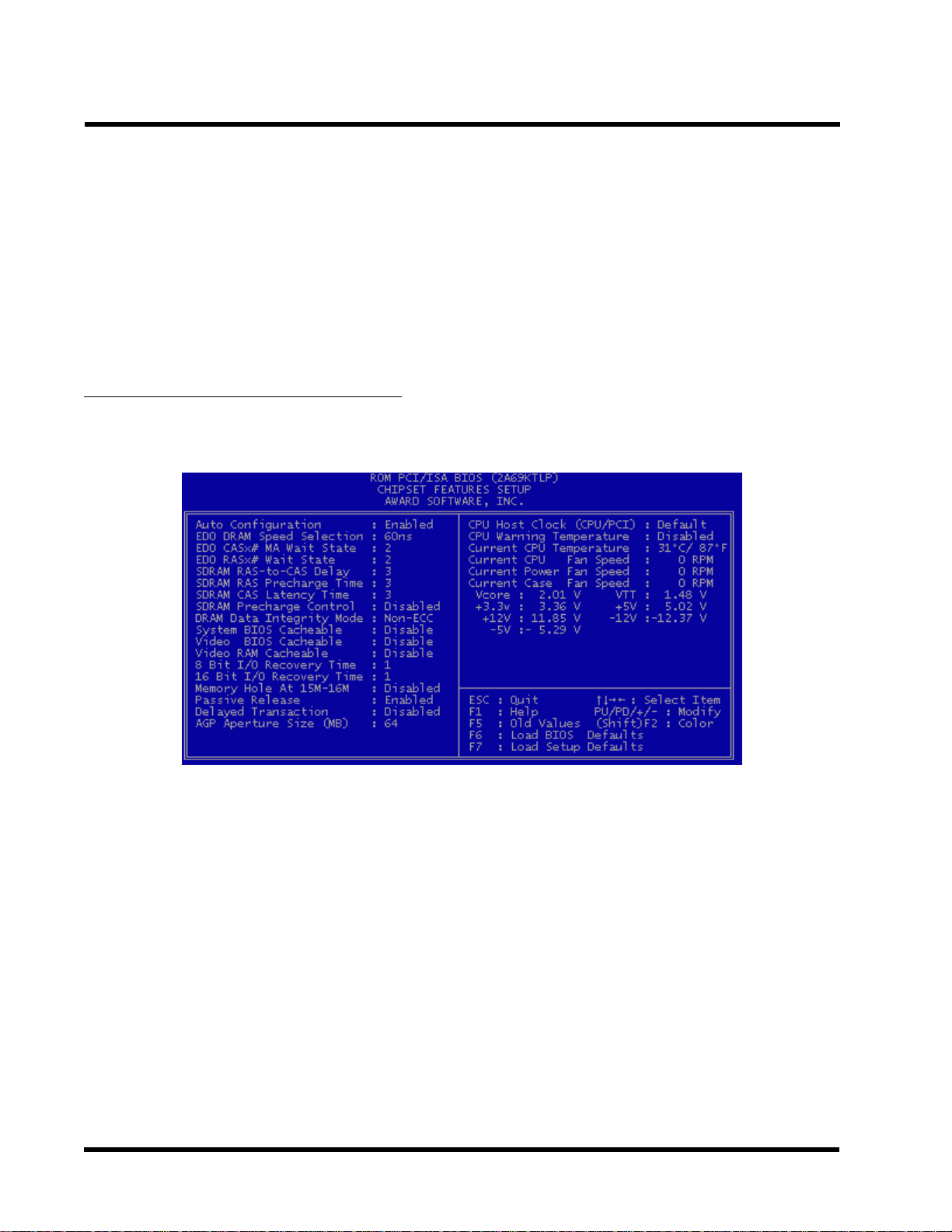
3.5 Chipset Features Setup
This option will change the values of the chipset registers and the system setting will alter . Do
not change any values if you are not familiar with the chipset.
•
Auto Configuration
Auto configuration selects predetermined optimal values of chipset parameters. When this
function is disabled, chipset parameters revert to setup information stored in CMOS. Many
fields in this screen are not available when Auto Configuration is enabled.
•
EDO DRAM Speed Selection
The value in this field depends on performance parameters of the installed EDO memory
chips (DRAM). Do not change the value from the factory setting unless you install new memory
that has a different performance rating than the original DRAMs.
•
EDO CASx# MA Wait State / EDO RASx# MA Wait State
Because the normal DRAM access speed is lower, CPU must wait for DRAM, this function
could set up DRAM Memory Access wait state.
Page 29

25 BIOS SETUP
•
SDRAM RAS-to-CAS Delay
This controls the latency between SDRAM active command and the read/write command.
Leave on default setting.
•
SDRAM RAS Precharge Time
This controls the idle clocks after issuing a precharge command to SDRAM. Leave on default setting.
•
SDRAM CAS Latency Time
This controls the SDRAM performance, default is 3 clocks. If your SDRAM DIMM specification is 2 CAS latency , change 3 to 2 for better performance.
•
SDRAM Precharge Control
This option is to determine the number of clocks required to deassert RAS and the timing for
SDRAM to do precharge before next RAS can be issued.
•
DRAM Data Integrity Mode
NON-ECC : Disable Error Correct Check function.
ECC : Enable Error Correct Check Function.
•
System BIOS Cacheable
Selecting “Enabled” allows caching of the system BIOS. This action can increase system
performance.
•
Video BIOS Cacheable
Selecting “Enabled” allows caching of the video BIOS. This action can increase system per-
formance.
•
Video RAM Cacheable
Selecting “Enabled” allows caching of the video RAM, which results in better system perfor-
mance. However, if any program writes to this memory area, a system error may occur .
•
8 Bit I/O Recovery Time
Recovery time is needed for old 8-bit ISA cards. Default setting is 1 ISA clock. If you find any
unstable 8-bit ISA card, you may try to extend the I/O recovery time.
•
16 Bit I/O Recovery Time
Recovery time is needed for 16-bit ISA cards. Default setting is 1 ISA clock. If you find any
unstable 16-bit ISA cards, you may try to extend the I/O recovery time.
Page 30

BIOS SETUP 26
•
Memory Hold At 15M-16M
Enabling this feature reserves memory address space from 15MB to 16MB to ISA expansion cards that specifically require this setting. This makes the memory from 15MB and up
unavailable to the system. Expansion cards can only access memory up to 16MB. The default is “Disabled”.
•
Passive Release
ISA access speed is lower than PCI access speed. While power on, the ISA interface would
release master bus control. The master bus control will go back ISA until other device accesses data.
•
Delayed Transaction
PCI access speed is faster than ISA. So PCI would release master bus to ISA interface for
accessing data. Then the master bus control would go back to PCI again.
•
AGP Aperture Size (MB)
Select the size of the Accelerated Graphics Port (AGP) aperture.The aperture is a portion of
the PCI memory address range dedicated to graphics memory address space. Host cycles
that hit the aperture range are forwarded to the AGP without any translation. For more information, please refer to www.agpforrum.org for AGP information.
•
CPU Host Clock (CPU/PCI)
This function allows you to set FSB frequency of the CPU and the speed of PCI bus. When
JP2 is set to 66MHz, then default FSB is 66MHz, and there are several options under
100MHz available. When JP2 is set to 100MHz, then default FSB is 100MHz, and there
are also several options above 100MHz available for you to choose.
•
CPU Warning Temperature
Enable this item to protect the CPU from overheating.
•
Current CPU FAN Speed
This item will show the fan speed of CPU by RPM.
•
Current Power FAN Speed
This item will show the fan speed of power by RPM.
•
Current CASE FAN Speed
This item will show the fan speed of case by RPM.
Page 31

27 BIOS SETUP
3.6 Power Management Setup
The Power Management Setup allows you to configure your system to save energy most effectively while operating in a manner consistent with your own style of computer use.
•
ACPI function
This item allows you to enable/disable the Advanced Configuration and Power Management
(ACPI).
The choice: Enabled, Disabled.
•
Power Management
This category allows you to select the type (or degree) of power saving and is directly related
to the following modes.
1. Doze Mode
2. Standby Mode
3. Suspend Mode
4. HDD Power Down
There are three selections for Power Management. Three of which have fixed mode settings.
1. Disable (Default) : No power management. Disable all four modes.
2. Min. Power Saving : Minimum power management mode. Inactivity peroid is
definded as below.
Doze Mode = 1 hr.
Standby Mode = 1 hr .
Suspend Mode = 1 hr.
HDD Power Down = 15 min.
Page 32

BIOS SETUP 28
3. Max. Power Saving : Maximum power management mode. Inactivity period is defined
as below .
Doze Mode = 1 min.
Standby Mode = 1 min.
Suspend Mode = 1 min.
HDD Power Down = 1 min.
4. User Defined : Allow you to set each mode individually . Select time-out period for each
mode shown above.
•
PM Control by APM
When enabled, an Advanced Power Management device will be activated to enhance the
Max. Power Saving mode and stop the CPU internal clock.
If the Max. Power Saving is not enabled, this will be preset to “No”.
•
Video Off Method
Determine the manner in which the monitor is blanked.
-V/H SYNC+BLANK : System turns off vertical and horizontal synchronization and ports
and writes blanks to the video buffer .
-DPMS : Select this option if your monitor supports the Display Power
Management Signaling (DPMS) standard of the Video Electronics
Standards Associatoin (VESA). Use the software supplied for your
video subsystem to select video power management values.
- Blank Screen : System only writes blanks to the video buffer.
•
Video Off After
Select the power-saving modes during which the monitor goes blank.
Doze : Monitor remains “on” during Doze modes.
Suspend : Monitor blanked when system enters Suspend mode.
N/A : It is default. When system enters power-saving mode, it does not do the video off
action.
•
MODEM Use IRQ
Y ou can select one of the following interrupt resources for modem use: 3.4.5.7.9.10.1 1.
There are three Green PC power saving functions. They are user-configurable only during User
Defined Power Management mode.
• Doze Mode
After the selected period of system inactivity (1 minute to 1 hour), the CPU clock runs at
slower speed while all other devices still operate at full speed.
Page 33

29 BIOS SETUP
• Standby Mode
After the selected period of system inactivity (1 minute to 1 hour), the fixed disk drive and the
video shut off while all other devices still operate at full speed.
• Suspend Mode
After the selected period of system inactivity (1 minute to 1 hour), all devices except the CPU
shut off.
• HDD Power Down
After the selected period of system inactivity (1 to 15 minutes), the hard disk drive powers
down while all other devices remain active.
• Throttle Duty Cycle
When the system enters Doze mode, the CPU clock runs only part of the time. Y ou may select
the percent of time that the clock runs.
• PCI/VGA Active Monitor
When enabled, any video activity restarts the global timer for Standby Mode.
• Soft-Off by PWR-BTTN
When set to “Instant-off”, the A TX switch can be used as a normal system power off button.
When set to “Delay 4 seconds”, you need to hold the A TX switch for more than 4 seconds if
you want to power off system.
• Ring Wake Up
This allows either setting of “Enabled” or “Disabled” for powering up the computer when the
modem receives a call and the computer is in the soft-off mode.
• LAN Wake Up
This allows you to remotely power up your system through your network by sending a wake up
frame or signal.
NOTE: This feature requires the network interface and an A TX power supply with at
least 720mA +5 V standby power.
• Time Wake Up
This item can power on your computer at the time you selected.
• Reload Global Timer Events
When enabled, an event occurring on each device listed below restarts the global timer for
Standby mode.
Page 34
BIOS SETUP 30
IRQ[3-7, 9-15], NMI
Primary IDE 0
Primary IDE 1
Secondary IDE0
Secondary IDE1
Floppy Disk
Serial Port
Parallel port
T o enable or disable the detection of IRQ 3-7, IRQ 9-15 or NMI interrupt events for powering down state transition.
These items enable or disable the detection of IDE, floppy,
serial and parallel port activities for powering down state
transition.Actually it detects the read/write to/from I/O ports.
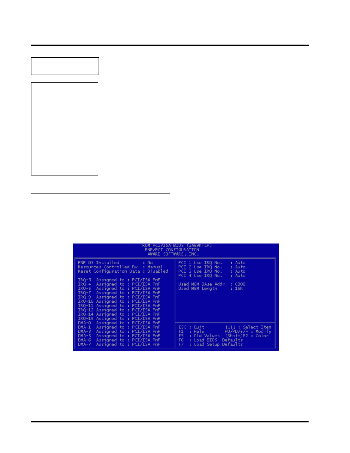
3.7 PnP/PCI Configuration Setup
This section describes configuring the PCI bus system. PCI (Personal Computer Interconnect)
is a system which allows I/O devices to operate at speeds nearing the speed that CPU itself uses
when communicating with its own special components. This section covers some very technical
items and it is strongly recommended that only experienced users can make some changes.
• PNP OS Installed
This field allows you to use a Plug-and-Play (PnP) operating system to configure the PCI bus
slots instead of using the BIOS. Thus interrupts may be reassigned by the OS when “Yes” is
selected. When a non-PnP OS is installed in order to prevent reassigning of interrupt set-
tings, select the default setting of “No”.
Page 35

31 BIOS SETUP
• Resource Controlled by
The Award Plug and Play BIOS can automatically configure all the boot and Plug and Play(PnP)
compatible devices. If you select “Auto”, all the interrupt request (IRQ) and DMA assignment
fields disappear , as the BIOS automatically assigns them.
The choice: Auto and Manual.
• Reset Configuration Data
Normally, you leave this field “Disabled”. Select “Enabled” to reset Extended System
Configuration Data (ESCD) when you exit “Setup”, if you have installed a new add-on and
the system reconfiguration has caused such a serious conflict that the operating
system cannot boot.
• IRQ-n Assigned to
When resources are controlled manually , assign each system interrupt as one of the following types, depending on the type of device using the interrupt.
- Legacy ISA Devices, requiring a specific interrupt (such as IRQ4 for serial port1), compliant with the original PC A T bus specification.
- PCI/ISA PnP devices, whether designed for PCI or ISA bus architecture, compliant with
the Plug and Play standard.
• DMA n Assigned to
When resources are controlled manually , assign each system DMA channel as one of the
following types, depending on the type of device using the DMA.
- Legacy ISA Devices, requiring a specific DMA channel, compliant with the original PC
A T bus specification,
- PCI/ISA PnP devices, whether designed for PCI or ISA bus architecture, compliant with
the Plug and Play standard.
• PCI 1,2,3,4 Use IRQ No.
These fields set how IRQ use is determined for each PCI slot. The default setting for each
field is “Auto”, which uses auto-routing to determine IRQ used. The other options are manual
settings of NA, 5, 7, 9, 10, 1 1, 12, 14 or 15 for each slot.
• Used MEM Base Addr
This field allows you to set the base address and block size of a legacy ISA card that uses
any memory segment within the C800H and DFFFH address range. If you have more than
one legacy ISA card in your system that requires to use this address range, you can increase
the block size to either 8K, 16K, 32K or 64K.
Page 36

BIOS SETUP 32
3.8 Integrated Peripherals
This option will load the default BIOS values. Choose the option and the following message
appears.
• •
• IDE HDD Block Mode
• •
The item means HDD access uses over one cycle method for improving HDD performance.
If the HDD supports this function, choose” Enabled”.
• IDE Primary/Secondary Master/Slave PIO
The four IDE PIO (Programmed Input/Output) fields let you set a PIO mode (0-4) for each of
the four IDE devices that the onboard IDE interface supports. Modes 0 through 4 provide
successively increased performance. In “Auto” mode, the system automatically determines
the best mode for each device.
• •
• IDE Primary/Secondary Master/Slave Ultra DMA
• •
Ultra DMA/33 implementation is possible only if your IDE hard drive can support and the
operating environment includes a DMA driver (Windows 95 OSR2 or a third-party IDE bus
master driver). If your hard disk drive and your system software can both support Ultra DMA/
33, select “Auto” to enable BIOS support.
Page 37

33
• •
• On Chip IDE Primary / Secondary PCI IDE
• •
The chipset contains a PCI IDE interface which supports two IDE channels. Select “Enabled”
to activate the first and/or second IDE interface. Select “Disabled” to deactivate an interface,
if you install a primary and/or secondary add-in IDE interface.
• •
• USB Keyboard Support
• •
Select “Enabled” if you have a USB keyboard.
BIOS SETUP
• Init Display First
This item allows you to decide to activate PCI Slot or AGP first.
• •
• POWER ON Function
• •
1 - Button only : Power on only by pushing button on the case (Default).
2 - Keyboard 98 : Y ou can power on system by pushing Power-On key of keyboard 98.
3 - Password : Power on only if you key in correct password.
4 - Hot KEY : Y ou can choose either of followings as hot key to power on the system.
A. CTRL + F1 ~ CTRL + F10
B. Mouse Left
C. Mouse Right
• •
• KBC Input Clock
• •
1 - 6MHz
2 - 8MHz
3 - 12MHz
4 - 16MHz
Set the frequency for the keyboard controller input clock.
• •
• Onboard FDC Controller
• •
Y ou can use this function to enable or disable Onboard FDC controller .
Page 38

BIOS SETUP 34
• •
• Onboard Serial Port 1
• •
Select an address and the corresponding interrupt for each of the first and second serial
ports.
The Choice: 3F8/IRQ4, 2F8/IRQ3, 3E8/IRQ4, 2F8/IRQ3, Disabled, Auto.
• •
• Onboard Serial Port 2
• •
The second serial port shares resources (address and IRQ) with IrDA.
• •
• UART Mode Select
• •
Normal : Normal operation
IrDA : IrDA compliant serial infrared port
ASKIR : Amplitude shift keyed infrared port
• •
• Onboard Parallel Port
• •
Select a logical LPT port name and matching address for the physical parallel (printer) port.
The choice: 378H/IRQ7, 278H/IRQ5, 3BCH/IRQ7, Disabled.
• •
• Parallel Port Mode
• •
This field allows you to set the operation mode of the parallel port. The setting “Normal”,
allows normal-speed operation but in one direction only; “EPP” allows bidirectional parallel
port operation at maximum speed; “ECP” allows the parallel port to operate in bidirectional
mode and at a speed faster than the maximum data transfer rate; “ECP+EPP” allows normal
speed operation in a two-way mode.
Page 39

35
BIOS SETUP
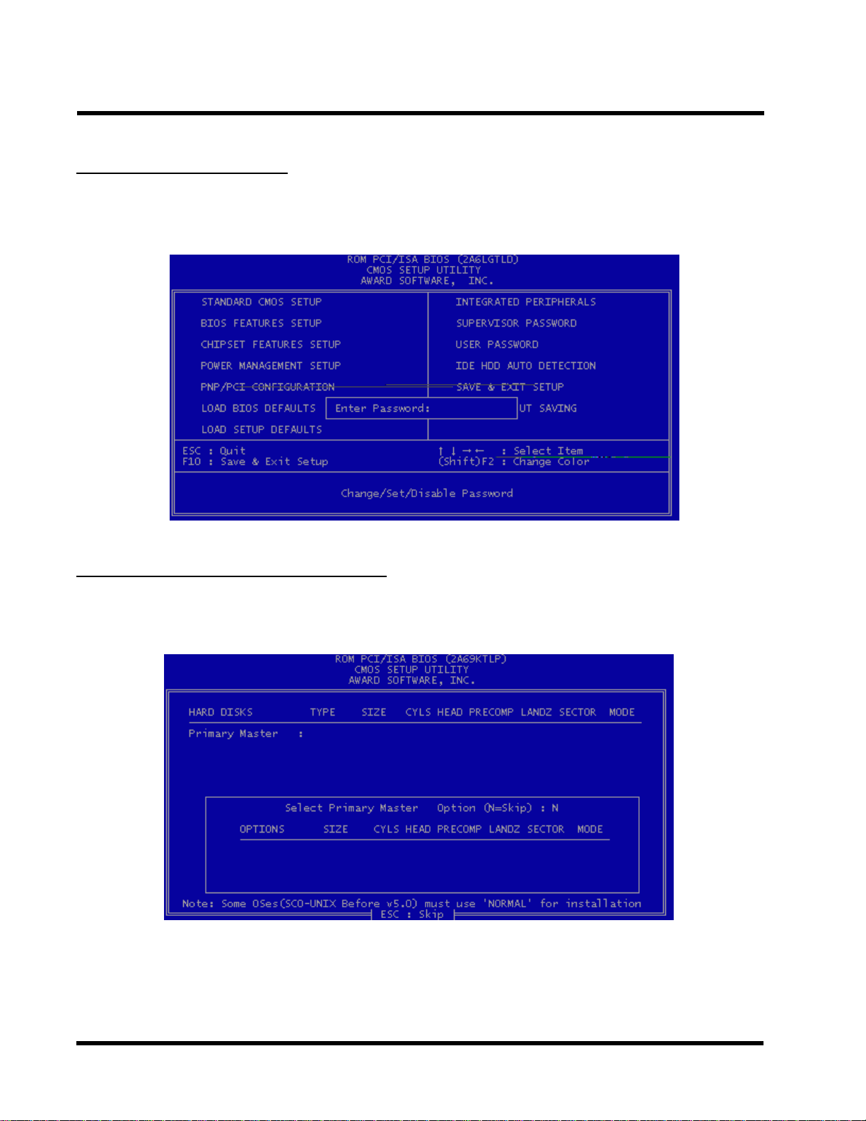
3.9 Supervisor Password
This option will set the password to prevent others from making changes to your system.
Password prevents unauthorized use of your computer. If you set a password, the system prompts
for the correct password before you boot or access to “Setup”
T o set a password:
1. At the prompt, type your password. Y our password can be up to 8 alphanumeric characters.
When you type the characters, they appear as asterisks on the password screen box.
2. After typing the password, press [Enter] key .
3. At the next prompt, re-type your password and press [Enter] key again to confirm the new
password. After the password entry , the screen automatically reverts to the main screen.
T o disable the password, press [Enter] key when prompted to enter the password. The screen
displays a message confirming that the password has been disabled.
Page 40
BIOS SETUP 36
3.10 User Password
This option will set the password to prevent others from making changes to your system when
accessed by POWER ON. This operation is same as SUPERVISOR P ASSWORD.
3.1 1 IDE HDD Auto Detection
Use the BIOS utility to detect the HDD type automatically . Press “Y” to accept, “N” to reject, and
“ESC” to the next detection.
Page 41

37
3.12 Save & Exit Setup
Save the setting and exit the BIOS utility .
BIOS SETUP
3.13 Exit Without Saving
Abort the current change and exit the BIOS utility .
Page 42
BIOS SETUP 38
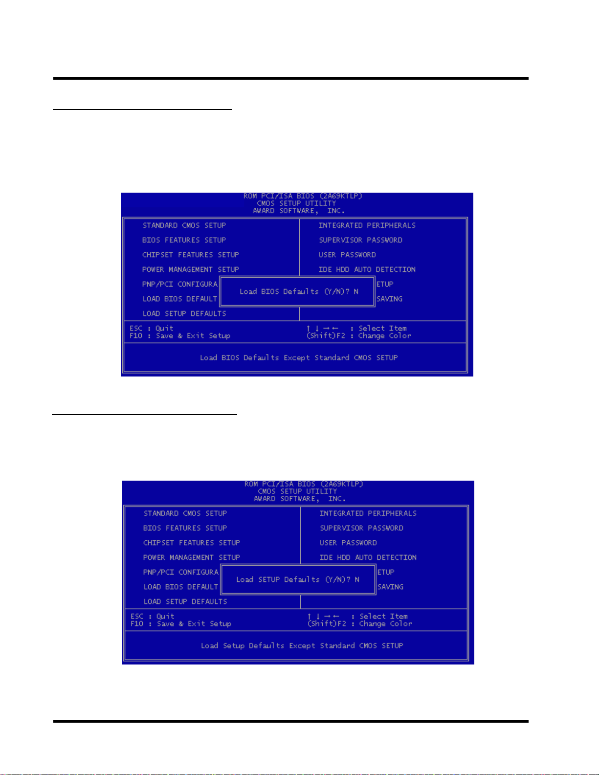
3.14 Load BIOS Defaults
NOTE: This option allows you to load the troubleshooting default values permanently
stored in the BIOS ROM. These default settings are non-optimal and disable all high
performance features.
3.15 Load Setup Defaults
This option allows you to load the default values to the system configuration fields. These
default values are the optimized configuration settings for the system.
Page 43

39
e
c
u
y
f
n
BIOS UPGRADE
4.1 How to Check Y our BIOS File Name and V ersion
Please turn on PC first, the screen will display as follows :
TRANSCEND MODULAR BIOS : ABX3A-V10
Y ou can see a description shows at the third line.
ABX3A - V1 0
BIOS Version 1.0 (V11 f
( You can upgrade to n
than this version.)
BIOS File Name
(Make sure the first 5
version, if you want to
or Version 1.1)
ewer version if your BIOS version is older
haractors must be the same as your own
pgrade your BIOS.)
4.2 Download Correct BIOS File from Web
Please enter Transcend Internet web : http://www.transcendusa.com.
Choose BIOS upgrade environment.
The BIOS file name consists of 5 characters. Check the exact BIOS to download. Y our BIOS file
name must absolutely match the one shown on our web. Then download the suitable version to
your disk.
Warning:
Your system coul
accidentl
choose, please co
used. I
be damaged, if a wrong BIOS version is
you are not sure what version you should
tact us at techsupport@transcend.com.tw
4.3 How to Update Y our Motherboard BIOS
Please follow these 5 steps listed below to update your BIOS.
Step 1: Make a record of your original or existing BIOS Setup parameters.
- Press [Del] during the Power On Self T est to enter BIOS Setup Program when you
start your system.
- Write down the value of each parameter in order to re-configure your system after
BIOS updating.
Page 44

BIOS UPDATE 40
Step 2: Make a System Disk
- Put a clean 3.5" disk in Drive A
MS-DOS : Key in
Windows O/S : Select the icon of [My Computer]
Step 3: Download the updated BIOS EXE file from the web site to a floppy disk.
(Ref 4.1 and 4.2)
Step 4: Execute the download file to decompress it.
Step 5: Please read the file of Readme.TXT carefully, and follow the instructions step by step.
Then you can finish the BIOS update.
FORMAT A:/S and press [Enter].
Click [3.5" Floppy (A:)]
Select [File/Format] from Command Bar
Under
Click [Start] button
Format 3.5 Floppy (A:) Menu select
Format type = Full item and
Other Options = Copy system files
 Loading...