

Page 1
22P Horizontal Type
T
S
4
G
S
D
O
M
2
2
H
T
S
4
G
S
D
O
M
2
2
H
T
S
4
G
S
D
O
M
2
2
H
SATA Flash Modules
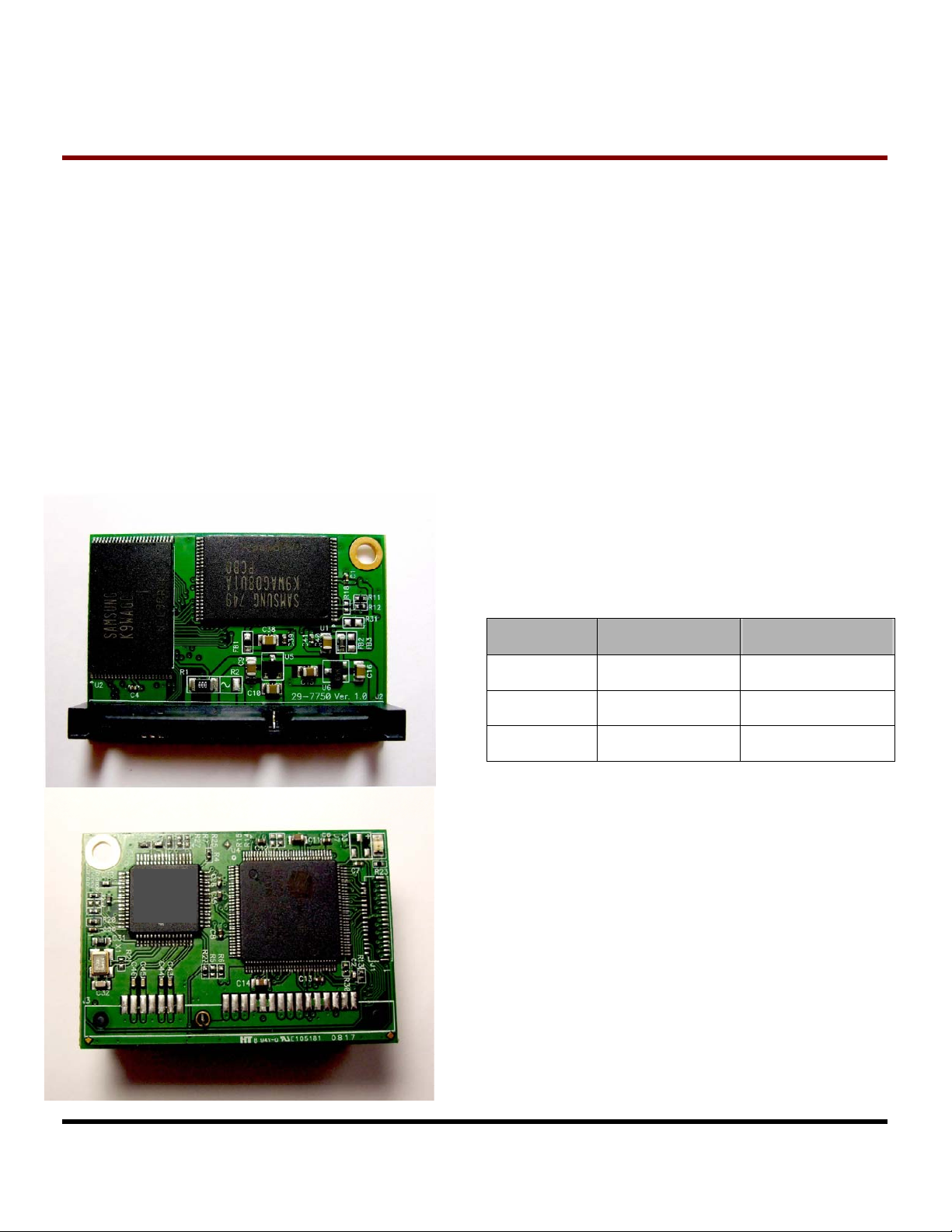
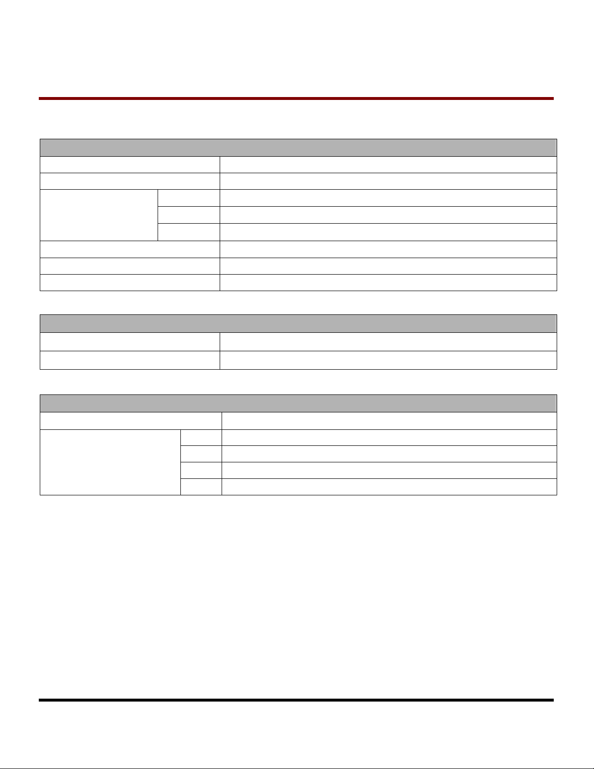
Description
Serial-ATA is designed as a successor to the
legacy SATA standard. The new standard is
dedicated to achieve higher transfer rate with thinner
cables and more reliable operation than Parallel ATA
interface. SATA Flash Modules is perfect
replacement storage device for PCs, Laptops,
gaming systems, and handheld devices.
Placement
Features
• RoHS compliant
• Fully compatible with devices and OS that support the
SATA 1.0a 1.5Gbps standard
• Non-volatile Flash Memory for outstanding data
retention
• Supports up to Ultra DMA Mode 4
• Built-in ECC (Error Correction Code) functionality and
wear-leveling algorithm ensures highly reliable of data
transfer
• 7P Signal + 15P Power male SATA connector
• Low Power Consumption
• Shock resistance
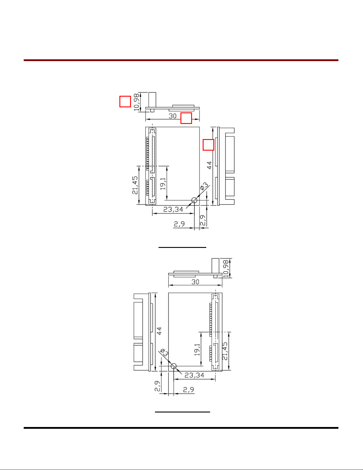
Dimensions
Side Millimeters Inches
A
B
C
* Please refer to Mechanical Drawing
44.00 ± 0.15 1.732 ± 0.006
33.57 ± 0.15 1.322 ± 0.006
10.98 ± 0.20 0.432 ± 0.008
Transcend Information Inc.
1
V1.1
Page 2
T
S
4
G
S
T
S
4
T
S
4
Specifications
Physical Specification
Form Factor
Storage Capacities
G
G
S
S
D
D
D
O
O
O
M
M
M
2
2
2
2
2
2
H
H
H
22P Horizontal Type
SATA Flash Modules Vertical Type
4GB(T.B.D)
SATA Flash Modules
Dimensions (mm)
Input Voltage
Weight
Connector
Environmental Specifications
Operating Temperature
Storage Temperature
Power Requirements
Input Voltage
4GB SATA Flash Modules
Power Consumption
(DC 5V
@25℃)
Length
Width
Height
Mode MAX (mA)
Write
Read
Standby
44.00 ± 0.15
33.57 ± 0.15
10.98 ± 0.20
5V ± 10%(default) / 3.3V ± 5%(option)
8 g
SATA 7+15 pins combo connector
0 ℃ to 70 ℃
- 40 ℃ to 85 ℃
5V ± 10%
171.1
178.8
112.6
Transcend Information Inc.
2
V1.1
Page 3
22P Horizontal Type
T
S
4
G
S
D
O
M
2
2
H
T
S
4
G
S
D
O
M
2
2
H
T
S
4
G
S
D
O
M
2
2
H
Reliability
Data Reliability
Data Retention
Connector Durability
Performance
Model P/N Read (KB/s) Write (KB/s) Random Read (KB/s) Random Write (KB/s)
4GB SATA Flash Module
* Note : The performance is based on Samsung K9KAG08U0M, dual channel. Environment: at 25 ℃, tested with
GA-8IG1000MK, 256 MB RAM, SATA interface support UDMA4, Windows
HDBENCH (version 3.4006), copied file 100MB
Built-in 4 symbol/page correction ECC
10 years
500 mating cycles
47473 18050 46778 5678
®
XP Version 2002 SP2, benchmark utility :
SATA Flash Modules
Actual Capacity
Model P/N Capacity C/H/S Capacity (BIOS) DOS Format (Bytes) Windows Format (Bytes)
4GB SATA Flash
Module
* Note: FAT32 format
Regulations
Compliance
4GB 7769 / 16 / 63 4009MB 4,001,169,408 4,001,169,408
CE, FCC and BSMI
Transcend Information Inc.
3
V1.1
Page 4
T
A
S
4
G
S
D
O
T
S
4
G
4
G
S
S
T
S
Mechanical Drawing
D
D
O
O
M
M
M
2
2
2
2
2
2
H
H
H
22P Horizontal Type
C
B
SATA Flash Modules
(Normal Type)
Transcend Information Inc.
(Reversed Type)
4
V1.1
Page 5

T
S
4
G
S
T
S
4
T
S
4
Pin Assignments
Pin No. Pin Name Pin No. Pin Name
01 GND 02 A+
03 A- 04 GND
05 B- 06 B+
07 GND 08 NC
09 NC 10 NC
11 GND 12 GND
13 GND 14 5V
15 5V 16 5V
17 GND 18 GND
19 GND 20 NC
21 NC 22 NC
G
G
S
S
D
D
D
O
O
O
M
M
M
2
2
2
2
2
2
H
H
H
22P Horizontal Type
SATA Flash Modules
Pin Layout
Pin 1
Transcend Information Inc.
5
V1.1
Page 6

T
S
4
G
4
4
G
G
S
S
S
T
S
T
S
Block Diagram
D
D
D
O
O
O
M
M
M
2
2
2
2
2
2
H
H
H
22P Horizontal Type
SATA Flash Modules
Data
SATA 7+15 PIN Connector
DC Characteristics
Supply Voltage V
High level output voltage V
bus
5V/3.3V
Parameter Symbol Min. Max.
PATA
to
SATA
Bridge
3.3V/1.8V
Voltage
Regulator
Data bus
Control
Signal
CC
OH
IDE / PATA
Flash Disk
Controller
Flash Memory
2.97 5.5 V
V
– 0.8 V
CC
D0 ~ D7
-CE0, -CE1…
Others
D8 ~ D15
-CE0, -CE1…
Unit Remark
Flash Memory
D0 – D7
-CE0 ~ -CE3
-WE…-RE
Flash Memory
D8 – D15
-CE0 ~ -CE3
-WE…-RE
Low level output voltage V
High level input voltage
Low level input voltage
Pull up resistance
Pull down resistance R
Transcend Information Inc.
2
OL
V
IH
V
IL
R
PU
PD
0.8 V
2.4 V Non-schmitt trigger
2.05 V Schmitt trigger
0.6 V Non-schmitt trigger
1.25 V Schmitt trigger
52.7 141 KOhm
47.5 172 kOhm
6
1
1
V1.1
Page 7

T
S
4
G
T
S
T
S
Command Set
S
4
G
S
4
G
S
1 Check Power Mode E5 or 98h – – – – Y – Support
2 Execute Drive Diagnostic 90h – – – – Y – Support
3 Erase Sector C0h – Y Y Y Y Y Not Support #3
4 Flush Cache E7h – – – – Y – Support
5 Format Track 50h – Y – Y Y Y Support
6 Identify Device ECh – – – – Y – Support
7 Idle E3h or 97h – Y – – Y – Support
8 Idle Immediate E1h or 95h – – – – Y – Support
9 Initialize Drive Parameters 91h – Y – – Y – Support
22P Horizontal Type
D
O
M
2
2
H
D
O
M
2
2
H
D
O
M
2
2
H
Command Code FR SC SN CY DH LBA Status Note
SATA Flash Modules
Key Management
10
Structure Read
Key Management Read
11
Keying Material
Key Management Change
12
Key Management Value
13 NOP 00h – – – – Y –
14 Read Buffer E4h – – – – Y – Support
15 Read DMA C8h – Y Y Y Y Y Support
16 Read Long Sector 22h or 23h –
17 Read Multiple C4h – Y Y Y Y Y Support
18 Read Sector(s) 20h or 21h – Y Y Y Y Y Support
19 Read Verify Sector(s) 40h or 41h – Y Y Y Y Y Support
20 Recalibrate 1Xh – – – – Y – Support
21 Request Sense 03h – – – – Y – Not Support #3
22 Security Disable Password F6h – – – – Y – Support
B9 (Feature
0-127)
B9 (Feature
80)
B9 (Feature
81)
Y Y Y Y Y – NOT Support #1
Y Y Y Y Y – NOT Support #1
Y Y Y Y Y – NOT Support #1
NOT Support
Y Y Y Y NOT Support #2
23 Security Erase Prepare F3h – – – – Y – Support
24 Security Erase Unit F4h – – – – Y – Support
25 Security Freeze Lock F5h – – – – Y – Support
26 Security Set Password F1h – – – – Y – Support
Transcend Information Inc.
7
V1.1
Page 8

22P Horizontal Type
T
S
4
G
S
D
O
M
2
2
H
T
S
4
G
S
D
O
M
2
2
H
T
S
4
G
S
D
O
M
2
2
H
27 Security Unlock F2h – – – – Y – Support
28 Seek 7Xh – – Y Y Y Y Support
29 Set Feature EFh Y – – – Y – Support
30 Set Multiple Mode C6h – Y – – Y – Support
31 Set Sleep Mode E6h or 99h – – – – Y – Support
32 Standby E2 or 96h – – – – Y – Support
33 Standby Immediate E0 or 94h – – – – Y – Support
34 Translate Sector 87h – Y Y Y Y Y Not Support #3
35 Wear Level F5h – – – – Y – Support #4
36 Write Buffer E8h – – – – Y – Support
37 Write DMA CAh – Y Y Y Y Y Support
38 Write Long Sector 32h or 33h – – Y Y Y Y Not Support #2
39 Write Multiple C5h – Y Y Y Y Y Support
SATA Flash Modules
40 Write Multiple w/o Erase CDh – Y Y Y Y Y Not Support #3
41 Write Sector(s) 30h or 31h – Y Y Y Y Y Support
42 Write Sector(s) w/o Erase 38h – Y Y Y Y Y Not Support #3
43 Write Verify 3Ch – Y Y Y Y Y Support
#1: This command is optional, depending on the key Management scheme in use.
#2: Use of this command is not recommended.
#3: CFA feature set command is not supported by P-ATA to S-ATA bridge controller.
#4: If Security command 22~27 are supported, this command is not supported.
Definitions
FR = Features Register
SC =Sector Count register (00H to FFH, 00H means 256 sectors)
SN = Sector Number register
CY = Cylinder Low/High register
DH = Head No. (0 to 15) of Drive/Head register
LBA = Logic Block Address Mode Support
– = Not used for the command
Y = Used for the command
Transcend Information Inc.
8
V1.1
Page 9

22P Horizontal Type
T
S
4
G
S
D
O
M
2
2
H
T
S
4
G
S
D
O
M
2
2
H
T
S
4
G
S
D
O
M
2
2
H
SMART Command Set
SMART Command Set
SMART Feature Register Values
D0h Read Data D4h Execute OFF-LINE Immediate
D1h Read Attribute Threshold D8h Enable SMART Operations
D2h Enable/Disable Autosave D9h Disable SMART Operations
D3h Save Attribute Values DAh Return Status
1. If reserved size is below the Threshold, the status can be read from Cylinder register by Return Status command
(DAh).
SMART Data Structure
BYTE F / V Decription
0-1 X Revision code
SATA Flash Modules
2-361 X Vendor specific
362 V Off line data collection status
363 X Self-test execution status byte
364-365 V Total time in seconds to complete off-line data collection activity
366 X Vendor specific
367 F Off-line data collection capability
368-369 F SMART capability
370 F Error logging capability
7-1 Reserved
0 1=Device error logging supported
371 X Vendor specific
372 F Short self-test routine recommended polling time (in minutes)
373 F Extended self-test routine recommended polling time (in minutes)
374 F Conveyance self-test routine recommended polling time (in minutes)
375-385 R Reserved
386-395 F Date Code
396 V Number of MU in device (0~n)
397+(n*6) V MU number
398+(n*6) V MU data block
Transcend Information Inc.
9
V1.1
Page 10

22P Horizontal Type
T
S
4
G
S
D
O
M
2
2
H
T
S
4
G
S
D
O
M
2
2
H
T
S
4
G
S
D
O
M
2
2
H
400+(n*6) V MU spare block
401+(n*6) V Init. Bad block
402+(n*6) V Last Defect Bad block ( Newest state)
511 V Data structure checksum
F=the content of the byte is fixed and does not change.
V=the content of the byte is variable and may change depending on the state of the device or
the commands executed by the device.
X=the content of the byte is vendor specific and may be fixed or variable.
R=the content of the byte is reserved and shall be zero.
* 4 Byte value : [MSB] [2] [1] [LSB]
SATA Flash Modules
Transcend Information Inc.
10
V1.1
Page 11

T
S
4
G
S
D
O
T
S
4
G
4
G
S
S
T
S
Ordering Information
D
D
O
O
M
M
M
2
2
2
2
2
2
H
H
H
22P Horizontal Type
SATA Flash Modules
TS XG SDOM XX
Connector type
7H = 7pin SATA horizontal
Transcend Product
Capacity:
1G~8G
1. The above technical information is based on industry standard data and has been tested to be reliable. However,
Transcend makes no warranty, either expressed or implied, as to its accuracy and assumes no liability in
connection with the use of this product. Transcend reserves the right to make changes to the specifications at any
time without prior notice.
2. For specific capacity, performance, and reliability requirement, please contact with sales.
TAIWAN
No.70, XingZhong Rd., NeiHu Dist., Taipei, Taiwan, R.O.C
TEL +886-2-2792-8000
Fax +886-2-2793-2222
E-mail:
www.transcend.com.tw
sales@transcend.com.tw
USA
Los Angeles:
E-mail:
Maryland:
E-mail:
www.transcendusa.com
CHINA
E-mail: sales@transcendchina.com
www.transcendchina.com
GERMANY
E-mail: vertrieb@transcend.de
www.transcend.de
HONG KONG
E-mail: sales@transcend.com.hk
www.transcendchina.com
JAPAN
E-mail: sales@transcend.co.jp
www.transcend.jp
THE NETHERLANDS
E-mail: sales@transcend.nl
www.transcend.nl
United Kingdom
E-mail: sales@transcend-uk.com
www.transcend-uk.com
sales@transcendusa.com
sales_md@transcendusa.com
22V = 22pin SATA vertical
22H = 22pin SATA
horizontal
SATA Flash Module
Transcend Information Inc.
11
V1.1
 Loading...