

Transcend TS-ABX11, TS-AZX11 User Manual

TS-ABX11
TS-AZX11
Intel
USER
’
®
Pentium® II / III
S MANUAL
TM
Series

TS-ABX11/TS-AZX11 Motherboard
Supporting Intel ® Slot 1 CeleronTM, Pentium® II, Pentium® III Series Processors
66/100 MHz Front Side Bus Frequency
Intel® 440BX/440ZX Chipset
Welcome !!
Congratulations on your purchase of this great value motherboard, with its range of special
features and innovative onboard functions, built around the advanced architecture of the new
®
440BX/440ZX Chipset. More details to follow later in this manual.
Intel
Our Website
Please come and visit us at our website on
of interesting information about this and many other quality Transcend products.
Your User’s Manual
This User’s Manual is designed to help end users and system manufacturers to set up and
install the motherboard. All of the information within has been carefully checked for accuracy .
However, Transcend Information, Inc. (hereafter referred to as “Transcend”) carries no
responsibility or liability for any errors or inaccuracies which this manual may contain. This
includes references to products and software. In addition, the information and specifications
are subject to change without prior notice.
http://www.transcendusa.com/ . You’ll find plenty
Disclaimer
Transcend provides this manual “as is” without any warranty of any kind, either expressed or
implied, including - but not limited to - the implied warranties, conditions of merchantability or
fitness for a particular purpose. Transcend, its management, employees, distributors and
agents are in no way liable for any indirect special, incidental or consequential damages,
including loss of profits, loss of business and the like. This is even if Transcend has been
advised of the possibility of such damages arising from any defect or error in this manual or
product.
Trademarks
All brands, product names and trademarks mentioned in this document are the property of
their respective owners or companies and are used solely for identification or explanation. It
is Transcend policy to respect all product rights.
Copyright
This manual may not, in whole or in part, be photocopied, reproduced, transcribed, translated
or transmitted, in whatever form or language, without the written consent of the manufacturer,
except for copies retained by the purchaser for personal archiving purposes.
Copyright© 1999-2000 Transcend Information, Inc.
Manual Version: 3.2
Release Date: May, 2000

Table of Contents
CHAPTER 1 INTRODUCTION 1
1.1 Package Contents ............................................................................................... 1
1.2 Specifications and Features ................................................................................. 1
CHAPTER 2 HARDWARE INSTALLATION 3
2.1 Transcend’s TS-ABX11/TS-AZX11 Motherboard ................................................. 3
2.2 Layout of Transcend’s TS-ABX11/TS-AZX1 1 Motherboard.................................... 4
2.3 CPU Installation .................................................................................................... 5
2.4 66/100MHz System Configuration.................................................................... 8
2.5 CPU Internal Frequency Ratio Settings............................................................ 8
2.6 Memory Configuration ................................................................................... 10
2.7 Keyboard Wake Up .................................................................................... 11
2.8 Primary / Secondary IDE Connectors ....................................................... 11
2.9 Floppy Disk Drive Connector .............................................................. 12
2.10 Fan Power Connectors .................................................................................. 12
2.11 Wake-on-LAN Connector ............................................................................ 13
2.12 IrDA-Compliant Infrared Module Connector ............................................ 13
2.13 Panel Connectors....................................................................................... 14
2.14 Power Connector......................................................................................... 15
2.15 External Connectors........................................................................................16
2.16 Clear CMOS Jumper........................................................................................ 17
2.17 SB-Link Connector...................................................................................... 17

CHAPTER 3 BIOS SETUP 18
3.1 BIOS Setup ........................................................................................................ 18
3.2 The Main Menu .................................................................................................. 18
3.3 Standard CMOS Setup ..................................................................................... 20
3.4 BIOS Features Setup ........................................................................................ 23
3.5 Chipset Features Setup ..................................................................................... 26
3.6 Power Management Setup ................................................................................ 29
3.7 PnP/PCI Configuration Setup............................................................................. 33
3.8 Integrated Peripherals .................................................................................... 35
3.9 Supervisor Password ....................................................................................... 38
3.10 User Password .................................................................................................. 39
3.11 IDE HDD Auto Detection ................................................................................39
3.12 Save & Exit Setup ............................................................................................. 40
3.13 Exit Without Saving .......................................................................................... 40
3.14 Load BIOS Defaults ......................................................................................... 41
3.15 Load Setup Defaults ........................................................................................ 41
CHAPTER 4 BIOS UPGRADE 42
4.1 How to Check Your BIOS File Name and Version ............................................ 42
4.2 Download the Correct BIOS File from the Web..................................................42
4.3 How to Update Your Motherboard BIOS ............................................................43

INTRODUCTION 1
CHAPTER 1 INTRODUCTION
1.1 Package Contents
This motherboard package contains the following items. If you discover any damaged or
missing items, please contact your retailer.
1 - TS-ABX11/TS-AZX11 Motherboard
2 - CD-ROM
3 - One FDD cable, one IDE cable
4 - User’s Manual
1.2 Specifications and Features
• •
• CPU
• •
- Supports Intel Pentium II 233MHz~450MHz
- Supports Intel Pentium III 450MHz~533MHz
• •
• Chipset
• •
- Intel 440BX/440ZX AGPset
• •
• DRAM Memory
• •
- Supports Synchronous DRAM
- 3pcs of 168-pin DIMM module sockets onboard for TS-ABX11
2pcs of 168-pin DIMM module sockets onboard for TS-AZX11
- 8~768MB memory capacity for TS-ABX11
8~256MB memory capacity for TS-AZX11
- 8/16/32/64/128/256MB SDRAM DIMM for TS-ABX11
8/16/32/64/128MB SDRAM DIMM for TS-AZX11
- 64 data bits or 72 data bits (ECC) structure for TS-ABX11
64 data bits structure for TS-AZX11
• •
• I/O BUS Slot
• •
- 1 AGP slot
- 5 Master / Slave PCI-BUS slots (PCI 2.1 compliant) for TS-ABX11
4 PCI-BUS slots for TS-AZX11
- 2 ISA BUS slots (one PCI/ISA shared)

2 INTRODUCTION
• •
• I/O Functions
• •
- Supports PIO Mode 3, 4 ATAPI devices and Ultra DMA/33
- Supports 2 high speed UART 16550 COM Ports
- Supports EPP/ECP LPT Port
- Support s1.44/2.88 MB floppy drive
- Supports PS/2 mouse and PS/2 keyboard
- Supports IrDA port
- Supports 2 Universal Serial Bus Ports
- Supports Creative® SB-LInk
•
Award BIOS
- Supports Plug-and-Play, PC98
TM
- Supports ACPI, DMI, Green Feature
•
Wake Up Features
- PS/2 mouse and keyboard Wake Up
- Supports Wake-on-LAN function
- Remote Ring Wake Up
•
PCB Dimensions
- ATX form factor, 4-layer PCB, 20.4cm x 30.5cm (8inch x 12inch)
HARDWARE INSTALLATION 3
CHAPTER 2 HARDWARE INSTALLATION
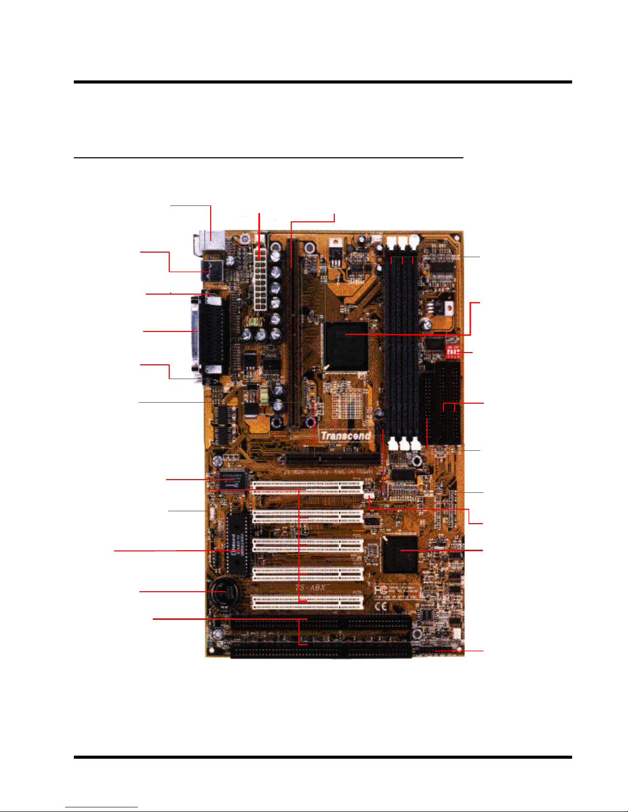
2.1 Transcend’s TS-ABX1 1/TS-AZX11 Motherboard
* T:PS/2 Mouse
**B:PS/2 Keyboard
* T:USB1
**B:USB2
**B:COMB
*T:Parallel
(Printer)
**B:COMA
AGP Port
Multi I/O Chip
ATX Power
Connector
Slot 1
***3 DIMM
Sockets
Intel 443BX/
443ZX Chipset
CPU Freq.-Ratio
DIP Switch
2 IDE
Connectors
Floppy Drive
Connector
66/100MHz
****5 PCI Slots
BIOS
Li Battery
2 ISA Slots
* T:Top
** B:Bottom
*** 3 DIMM Sockets for TS-ABX11, 2 DIMM Sockets for TS-AZX11
**** 5 PCI slots for TS-ABX11, 4 PCI slots for TS-AZX11
Wake-on-LAN
Intel PIIX4
Chipset
Panel
Connector
4 HARDWARE INSTALLATION
y
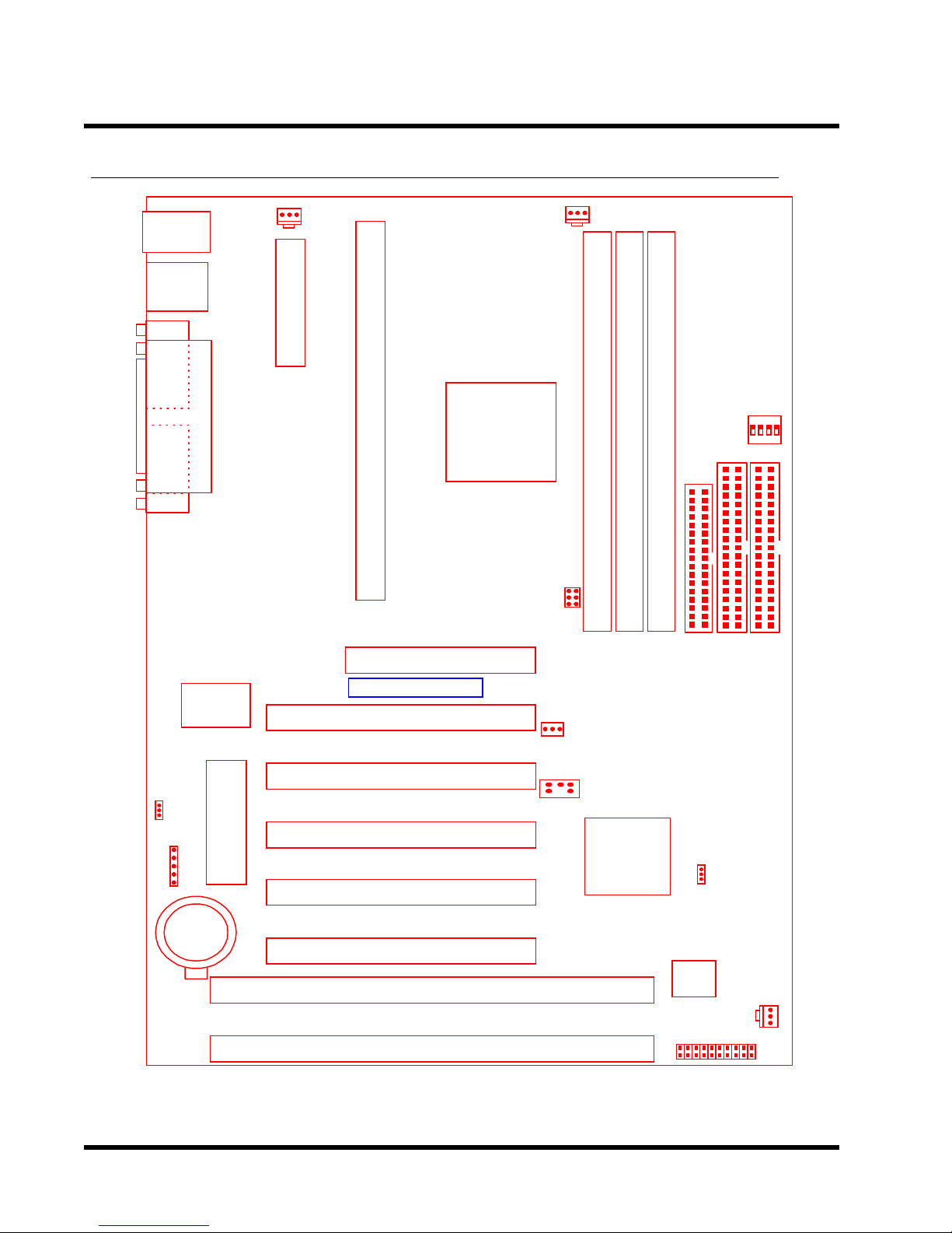
2.2 Layout of T ranscend TS-ABX11/TS-AZX11 Motherboard
KB MOUSE
PS/2
T:Mouse
B:Ke
board
USB
USB
T:Port 1
B:Port 2
COMB
Printer
Parallel Port
COMA
POWER-FAN
ATX Power Connector
Slot 1
443BX/ZX
AGP Set
AGP
Intel
CPU-FAN
CPU Freq.-Ratio
DIP Switch
SW1
DIMM1 (64/*72bit 168pin SDRAM Module)
DIMM2 (64/*72bit 168pin SDRAM Module)
**DIMM3 (64/*72bit 168pin SDRAM Module)
66/100MHzJP1
FDC
IDE2
IDE1
Multi-I/O
&
Keyboard
Controller
Transcend
PCI Slot 1 (PCI1)
PCI Slot 2 (PCI2)
JP5
KB-AWK
(BIOS)
PCI Slot 3 (PCI3)
2Mbit Flash
IrDA
PCI Slot 4 (PCI4)
Li Battery
***PCI Slot 5 (PCI5)
ISA Slot 1 (ISA1)
ISA Slot 2 (ISA2)
*72 bits ECC structure is valid for TS-ABX11 only.
**PCI slot 5 is present in TS-ABX11 only.
***DIMM3 is present in TS-ABX11 only.
Wake-on-LAN
WOL
SB_Link
Intel
Chipset
PIIX4
JP4
CMOS-CLR
Hardware
Monitor
Panel Connector
CASE-FAN
HARDWARE INSTALLATION 5
O
R
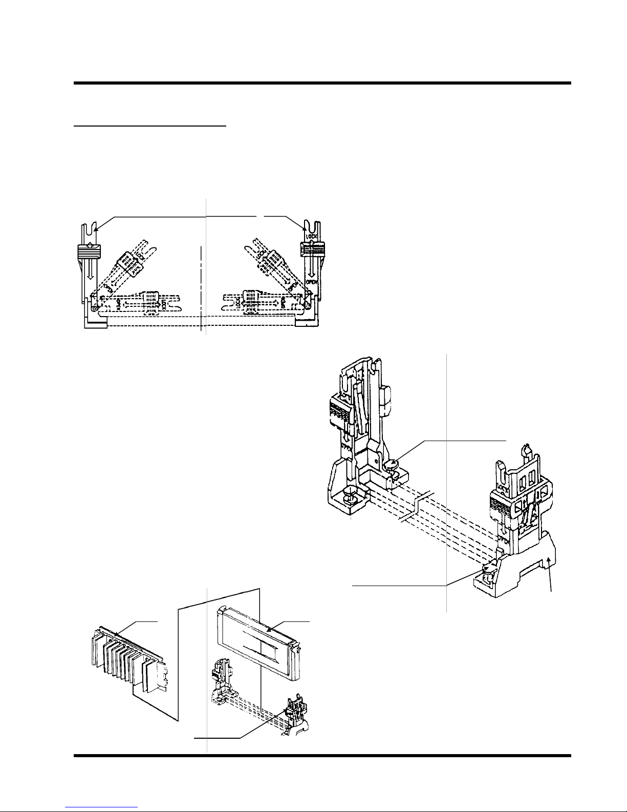
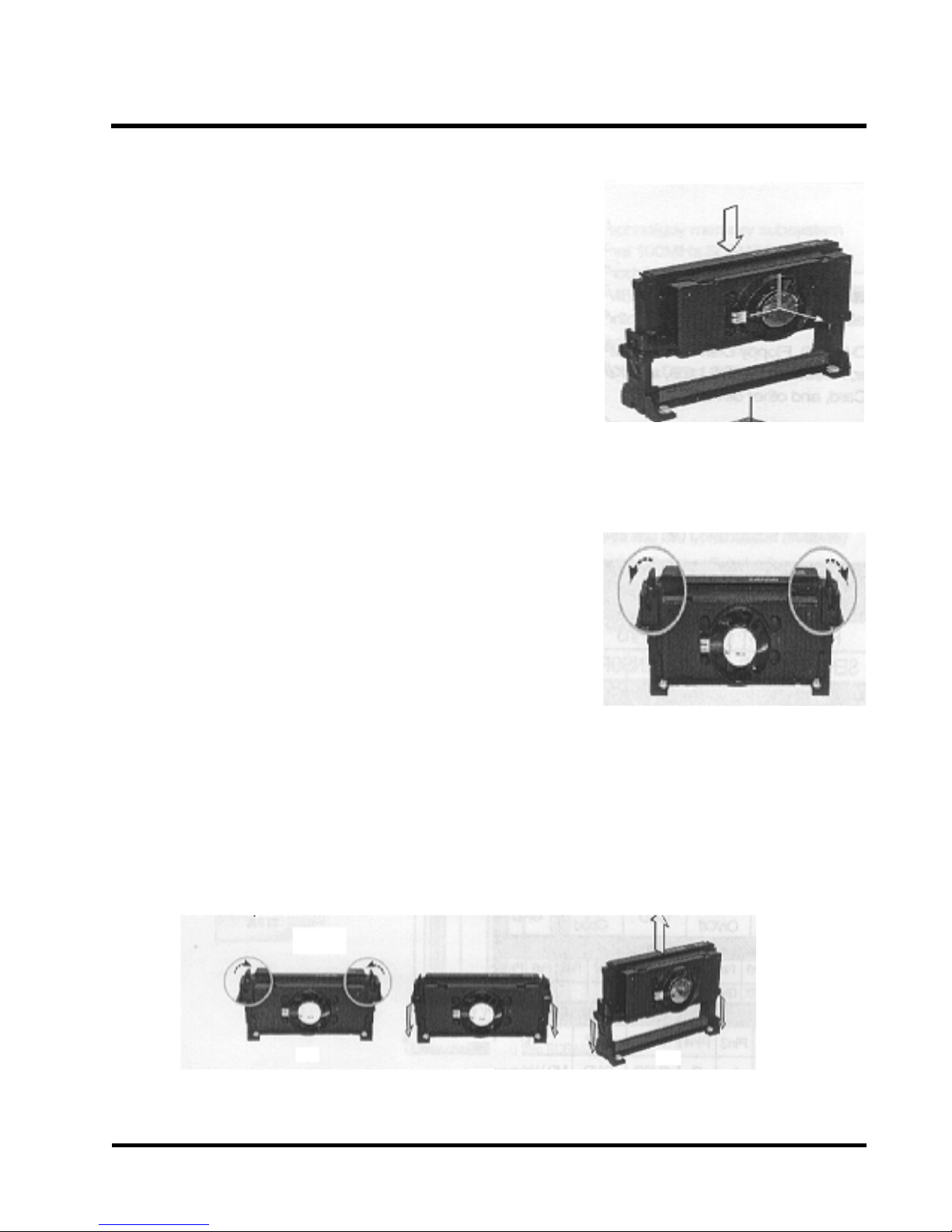
2.3 CPU Installation
•UNIVERSAL RETENTION MODULE (URM) INSTALLATION
EAR
LOCK
OPEN
UNIVERSAL RETENTI
N MODULE
2. Insert the BOARDLOCK BODY into the MAIN
BODY. Then turn the BOARDLOCK BODY
clockwise until it can be turned no more (there is
a stopper device on the MAIN BODY). Then the
BOARDLOCK BODY is secured on the MAIN
BODY.
3. Push the BOARDLOCK PINs all the way down.
The PINs automatically turn to an angle and lock
inside the BOARDLOCK BODYs. Then pull the
PIN back up to the stopper in order for the
BOARDLOCK BODY to be easily inserted into the
PC BOARD. For the ease in installation,
BOARDLOCK BODYs should be inserted into the
UNIVERSAL RETENTION MODULE before it is
installed onto the PC BOARD. Then you only need
to push the BOARDLOCK PINs all the way down
and the MODULE would be set up tightly on the
PC BOARD.
1. Before installing the UNIVERSAL RETENTION
MODULE, pull the supporting EARs 90o outward
until you hear a “Click” and both EARs sit upright
in the notches of the main body .
DLOCK BODY
BOA
CPU
PC
BOARD
BOARDLOCK BODY
MAIN BODY
CPU
4. When the UNIVERSAL RETENTION MODULE
is installed on the PC BOARD, move the SLIDER
to the LOCK position to lock in the CPU. To
remove the CPU, push the SLIDER down to the
OPEN position to unlock it.
6 HARDWARE INSTALLATION
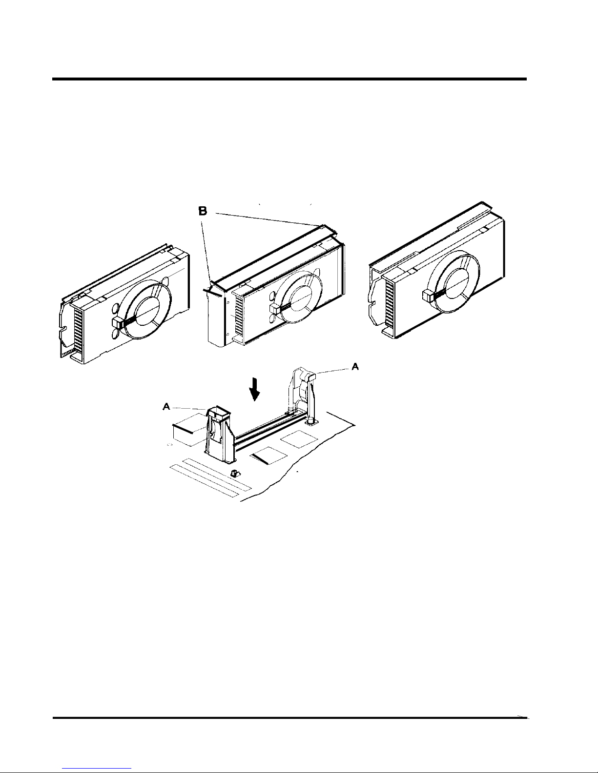
•The Intel Processor Type
Intel Celeron Intel Pentium II Intel Pentium III
Processor Processor Processor
(S.E.P.P) (S.E.C.C) (S.E.C.C.2)
A-(the Retention Mechanism)
B-(the Processor Latches)
NOTE:The retention mechanism must support your specific processor. Some retention
mechanism may not support all processors. Contact your motherboard retailers or refer
to your motherboard documentation if you have any questions.
If the Intel Pentium II processor is S.E.C.C package only, push the processor latches [B]
in completely to install.
Carefully slide the proceessor into the retention mechanism and connector.
HARDWARE INSTALLATION 7
•The Intel Processor Installation
Step1: Install the Processor in Slot 1
Slide the processor into the URM assembly and insert it
in Slot 1, while making sure that the heat sink assembly
is facing towards the chipset, as shown in the figure.
Press down firmly on the CPU until it is fully seated in
the Slot 1 connector.
IMPORTANT: The Slot 1 connector is directionally
keyed and the processor will not go in unless it is
properly oriented. Do Not apply excessive force
when installing the CPU.
Step 2: Lock the CPU in the URM
Lock the processor into the URM by pushing the top-right
and -left latches to the outward position as shown in the
illustration.
Step 3: How to Remove the Processor
(A) Unlock the CPU by pushing the top-right and -left
latches inward.
(B) Push both slides on the URM right and left branches
downward.
(C) Remove the processor by pulling it upward while
holding the two slides in the down position.
A B C
8 HARDWARE INSTALLATION
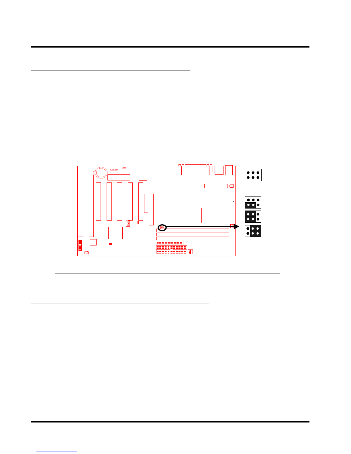
2.4 66/100MHz System Configuration
Jumper 1 (JP1) allows you to set the FSB (Front Side Bus) to either 66 or 100MHz configuration.
When you set the FSB to 66MHz, you can select a system bus frequency from 66MHz to
83.3MHz through “CPU Host Clock (CPU/PCI)” of “Chipset Features Setup” in BIOS Setup
(Please refer to page 26). When you set the FSB to 100MHz, you can select a system bus
frequency from 100MHz to 150MHz through “CPU Host Clock (CPU/PCI)” of “Chipset Features
Setup” in BIOS Setup (Please refer to page 26).
NOTE:If you are not familar with this feature, we recommend you set this jumper to “AUTO”
1
Transcend
1
1
1
JP1
100MHz
66MHz
AUTO
TS-ABX11/TS-AZX11 66/100MHz FSB Configuration Jumper
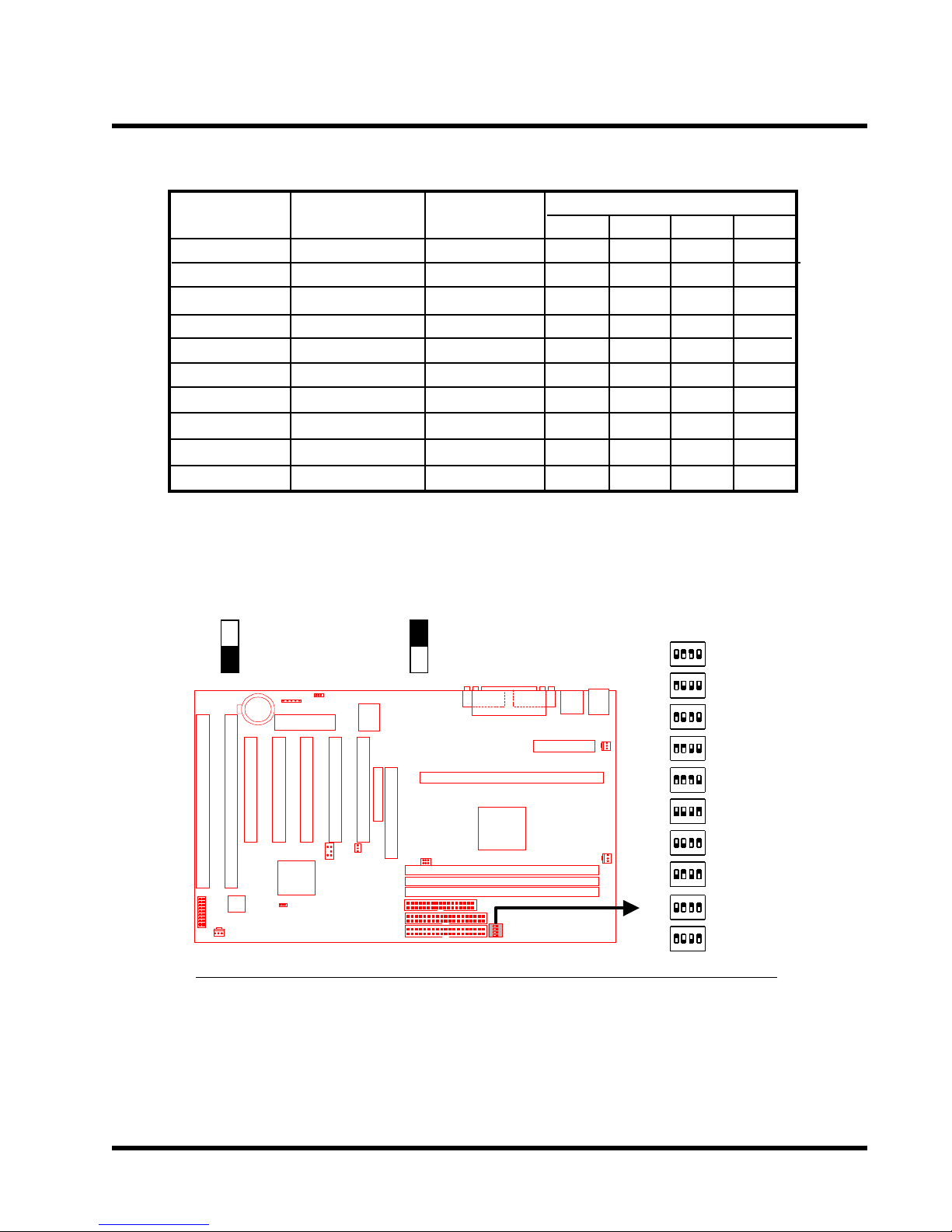
2.5 CPU Internal Frequency Ratio Setting
Switch 1 (SW1) is for adjusting the CPU internal frequency ratio. The frequency ratio is shown
in the table overleaf. The internal frequency can be calculated by the following formula:
CPU internal frequency = frequency ratio x system bus frequency *
* System bus frequency is set in “CPU Host Clock (CPU/PCI)” of “Chipset Features Setup” in
BIOS Setup (Please refer to page 26).
NOTE: Because Intel has locked the frequency ratio for new CPUs, setting SW1 to
adjust the frequency ratio is useless. However, it is effective for old version CPUs.
HARDWARE INSTALLATION 9
CPU Internal
Frequency
233/350MHz
266/400MHz
300/450MHz
333/500MHz
366/550MHz
400/600MHz
433/650MHz
466/700MHz
500/750MHz
533/800MHz
: ON(O) : OFF(X)
JP1
66/100MHz
66/100MHz
66/100MHz
66/100MHz
66/100MHz
66/100MHz
66/100MHz
66/100MHz
66/100MHz
66/100MHz
Transcend
Freq.-Ratio
x 3.5
x 4.0
x 4.5
x 5.0
x 5.5
x 6.0
x 6.5
x 7.0
x 7.5
x 8.0
1
O
X
X
X
X
O
O
O
O
X
2
X
O
O
X
X
O
O
X
X
O
SW1
SW1
ON DIP
1 2 3 4
ON DIP
1 2 3 4
ON DIP
1 2 3 4
ON DIP
1 2 3 4
ON DIP
1 2 3 4
ON DIP
1 2 3 4
ON DIP
1 2 3 4
ON DIP
1 2 3 4
ON DIP
1 2 3 4
ON DIP
1 2 3 4
3
X
O
X
O
X
O
X
O
X
O
4
O
O
O
O
O
X
X
X
X
X
Ratio
x 3.5
x 4.0
x 4.5
x 5.0
x 5.5
x 6.0
x 6.5
x 7.0
x 7.5
x 8.0
TS-ABX11/TS-AZX11 CPU Freq.-Ratio DIP Switch Setting
10 HARDWARE INSTALLATION
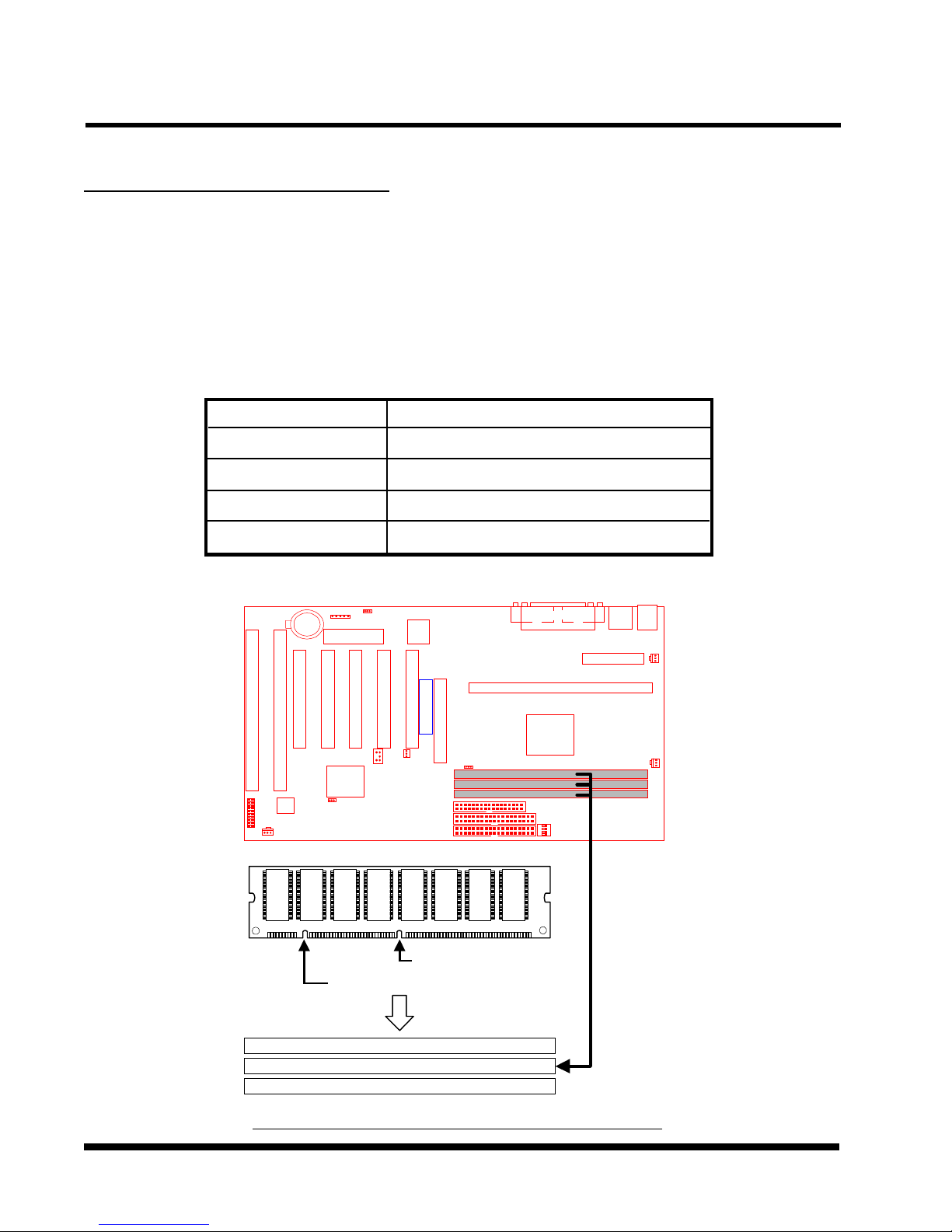
2.6 Memory Configuration
This motherboard must be installed with DIMMs (Dual Inline Memory Modules). The DIMMs
must be 3.3 Volt synchronous DRAM modules. It also supports ECC (Error Checking and
Correcting), which is valid for TS-ABX11 only.
IMPORTANT: Memory speed setup is required through “Auto Configuration“ in BIOS
Chipset Features Setup.
Install memory in any combination as follows:
DIMM Location
DIMM1
DIMM2
*DIMM3
**Total Memory
*DIMM3 is for TS-ABX11only.
**768 MB is maximum for the TS-ABX11, while 256MB is maximum for the TS-AZX11.
SDRAM 8,16, 32, 64,128, 256MBytes
SDRAM 8,16, 32, 64,128, 256MBytes
SDRAM 8,16, 32, 64,128, 256MBytes
768MBytes (max.)
Transcend
168-pin DIMM
168Pin SDRAM Module (DIMM1)
168Pin SDRAM Module (DIMM2)
168Pin SDRAM Module (DIMM3)
TS-ABX11/TS-AZX11 168Pin DIMM Sockets
3.3V Position
Unbuffered Position
HARDWARE INSTALLATION 11
y
2.7 Keyboard Wake Up (3-pin KB-AWK)
This function enables you to use the keyboard to power up the system. Set this jumper to
“Enable” if you wish to use your keyboard to power up your computer.
JP5
1
KB-AWK
Transcend
1
1
Disable
Enable
TS-ABX11/TS-AZX11 Keyboard Wake Up
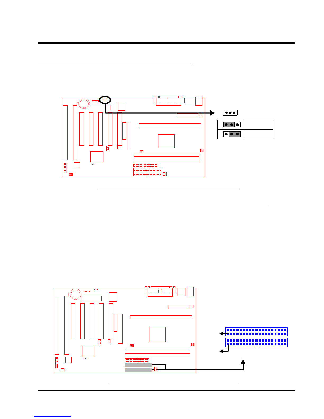
2.8 Primary / Secondary IDE Connectors (Two 40-pin IDE)
This motherboard supports two 40-pin IDE connectors marked as IDE1 (primary IDE channel)
and IDE2 (secondary IDE channel). Each channel supports two IDE devices which makes a
total of four devices. In order to work together, two devices on each channel must be set
differently to master and slave modes, either one of which a can be hard disk or CD-ROM.
The setting as master or slave mode depends on the jumper on your IDE devices. Please
refer to their manual accordingly. Connect your first IDE hard disk to the master mode of the
primary channel.
TS-ABX11/TS-AZX11 IDE Connectors
Transcend
Note: Make sure that the red
stripe is next to Pin1
IDE2
PIN1
IDE1
PIN1
Secondar
Primary IDE Connector
IDE Connector
 Loading...