

Transcend TS-AWE3, TS-AWH3 User Manual

TS-AWE3
TS-AWH3
USER’S MANUAL
Intel
®
Socket 370 Celeron
TM
Pentium® III FC-PGA Series
Transcend
Your Supplier, Your Partner,
/
Your Friend.

TS-A WH3 / TS-AWE3 Motherboard
Supporting Intel ® Pentium® III / Celeron™ Series Processor
66/100/133MHz Front Side Bus
Intel® 810-DC100 / 810E Chipset
Welcome !!
Congratulations on your purchase of this great value motherboard, with its range of special
features and innovative onboard functions, built around the advanced architecture of the new
Intel® 810-DC100 / 810E Chipset. More details to follow later in this manual.
Our Website
Please come and visit us at our website on http://www.transcendusa.com/ Y ou’ll find plenty of
interesting information about this and many other quality Transcend products.
Your User’s Manual
This User’s Manual is designed to help end users and system manufacturers to set up and
install the motherboard. All of the information within has been carefully checked for accuracy .
However, Transcend Information, Inc. (hereafter referred to as “Transcend”) carries no
responsibility or liability for any errors or inaccuracies which this manual may contain. This
includes references to products and software. In addition, the information and specifications
are subject to change without prior notice.
Disclaimer
Transcend provides this manual “as is” without any warranty of any kind, either expressed or
implied, including – but not limited to – the implied warranties, conditions of merchantability or
fitness for a particular purpose. Transcend, its management, employees, distributors and agents
are in no way liable for any indirect special, incidental or consequential damages, including loss
of profits, loss of business and the like. This is even if Transcend has been advised of the
possibility of such damages arising from any defect or error in this manual or product.
Trademarks
All brands, product names and trademarks mentioned in this document are the property of their
respective owners or companies and are used solely for identification or explanation. It is
Transcend policy to respect all product rights.
Copyright
This manual may not, in whole or in part, be photocopied, reproduced, transcribed, translated
or transmitted, in whatever form or language, without the written consent of the manufacturer,
except for copies retained by the purchaser for personal archiving purposes.
Manual Version: 1.00
Release Date: April 2000
Copyright © 2000 Transcend Information, Inc.

Table of Contents
CHAPTER 1 INTRODUCTION 1
1.1 Essential Handling Precautions.......................................................................1
1.2 Package Contents..........................................................................................2
1.3 Specifications and Features.............................................................................2
CHAPTER 2 HARDWARE INSTALLATION 5
2.1 Transcend’s TS-AWH3/TS-AWE3 Motherboard...........................................5
2.2 Layout of Transcend’s TS-AWH3/TS-AWE3 Motherboard..............................6
2.3 66/100/133MHz System configuration...........................................................7
2.4 Memory Configuration..................................................................................8
2.5 Keyboard Wake Up......................................................................................9
2.6 Primary / Secondary IDE Connectors............................................................10
2.7 Floppy Disk Drive Connector........................................................................11
2.8 Fan Power Connectors................................................................................12
2.9 Wake-on-LAN Connector..............................................................................13
2.10 IrDA-Compliant Infrared Module Connector....................................................14
2.11 Panel Connectors.........................................................................................15
2.12 Power Connector.........................................................................................17
2.13 External Back Panel I/O Ports........................................................................18
2.14 Using Jumper JPS to clear CMOS.....................................................................19
2.15 FWH Lock Jumper........................................................................................20
2.16 Onboard Audio Setting..................................................................................21
2.17 Internal Audio Connector............................................................................22
2.18 Internal Serial Port Connector COMB ..........................................................23

CHAPTER 3 BIOS SETUP 24
3.1 BIOS Setup ............................................................................................... 24
3.2 The Main Menu ......................................................................................... 24
3.3 Standard CMOS Features........................................................................... 26
3.4 Advanced BIOS Features............................................................................ 29
3.5 Advanced Chipset Features ........................................................................ 32
3.6 Integrated Peripherals .................................................................................34
3.7 Power Management Setup...........................................................................38
3.8 PnP/PCI Configuration Setup....................................................................... 41
3.9 PC Health Status ........................................................................................43
3.10 Frequency/Voltage Control..........................................................................44
3.11 Load Fail-Safe Default.................................................................................45
3.12 Load Optimized Defaults.............................................................................45
3.13 Supervisor Password..................................................................................46
3.14 User Password...........................................................................................47
3.15 Save & Exit Setup.......................................................................................47
3.16 Exit Without Saving ................................................................................... 48
CHAPTER 4 SOFTW ARE SETUP 49
4.1 INF Update for 810 Chipset ....................................................................... 49
4.2 VGA Driver Setup.......................................................................................50
4.3 Intel Security Controller Driver.....................................................................51
4.4 Audio Driver Setup.......................................................................................52
CHAPTER 5 BIOS UPGRADE 57
5.1 How to Check Your BIOS File Name and Version ........................................ 57
5.2 How to Download Correct BIOS File from Web............................................... 57
5.3 How to Update Your Motherboard BIOS ..................................................... 58

INTRODUCTION 1
CHAPTER 1 INTRODUCTION
1.1 Essential Handling Precautions
IMPORTANT. Read this page before unpacking your motherboard!
• Power Supply
Be careful! Always ensure that the computer is disconnected from the power supply when
working on the motherboard and its components.
• Static Electricity
Static electricity may cause damage to the delicate integrated circuit chips on your
motherboard. Before handling the motherboard outside of its protective packaging, ensure
that there is no static electric charge in your body. T o avoid this risk, please observe these
simple precautions while handling the motherboard and other computer components:
1. If possible, wear an anti-static wrist strap. This fits around your wrist and is connected to
a natural earth ground.
2. T ouch a grounded or anti-static surface, or a metal fixture such as a pipe or the chassis of
your system, before touching the motherboard.
3. When you have removed the motherboard from its anti-static packaging, try to hold it only
by the edges, without touching any components.
4. Avoid contacting the components on add-on cards, motherboards, and modules with the
golden fingers (gold-colored connectors) which plug into the expansion slots.
5. It is safest to handle system components only by their mounting brackets.
6. Keep components which are not connected to the system in the anti-static packaging
whenever possible.
These precautions help to reduce the risk of static build-up and ensure any static discharge is
harmless to your equipment.
••
• Battery Replacement
••
The battery which holds the system settings memory on your motherboard should not require
replacement for at least five years, and probably much longer. In picture 2.2, it is located near
the bottom right hand corner.

2 INTRODUCTION
Please replace your battery only with the same type, or a similar type recommended by the
manufacturer . If the battery is replaced incorrectly, there is a risk of a short circuit or explosion.
Used batteries should disposed of according to the manufacturer’s instructions.
••
• Electric Screwdrivers
••
To reduce the risk of damage to the motherboard due to excessive torque, avoid setting
electric screwdrivers above 7.5 kg/cm.
1.2 Package Contents
This motherboard package should contain the following items. Please check them as soon as
you unpack. If you find any damaged or missing items, please contact your retailer.
- TS-AWH3/TS-A WE3 motherboard
- 1 X CD-ROM
- 1 X FDD cable
- User’s Manual
- COM port cable x 1
- Ultra DMA / 66 cable x 1
1.3 Specifications and Features
• •
• CPU
• •
- Supports Intel® Petium III / CeleronTM Series
• •
• Chipset
• •
- TS-AWH3 : Intel® 810-DC100 Chipset (GMCH, ICH); FSB:66/100 MHz
- TS-AWE3 : Intel® 810E Chipset (GMCHE, ICH); FSB: 66/100/133 MHz
• •
• Display Cache Memory
• •
- 4MB Display Cache SDRAM
• •
• DRAM Memory
• •
- Supports Synchronous DRAM
- 3 X 168-pin DIMM module sockets on board
- 8~512MB memory size
- 8/16/32/64/128/256MB SDRAM DIMM
- 64 data bits structure only

INTRODUCTION 3
• •
• I/O Bus Slot
• •
- 5 X Master / Slave PCI Bus slots (PCI 2.2 compliant)
- 1 X AMR (Audio/MODEM Riser) slot
•
Award BIOS
- Supports PC99, Plug-and-Play
- Supports ACPI,APM,DMI, Green Feature
• •
• I/O Functions
• •
- Support PIO Mode 3,4 A T API devices and Ultra DMA/33/66
- Supports 2 high speed UART 16550 COM ports
- Supports SPP/EPP/ECP LPT port
- Supports 3 mode/1.44/2.88MB floppy drive
- Supports PS/2 Mouse and PS/2 Keyboard
- Supports IrDA port
- Supports 2 USB (Universal Serial Bus) ports
- Supports VGA port
- Supports Line-out, Line-in and MIC-in jack
- Supports Game/MIDI port
•
Switching Voltage Regulator
- Intel VRM 8.4 compliant
•
Other Features
- Year 2000 compliant
- Power failure resume
- FWH (Firmware Hub) supports security manageability
- BIOS Virus protection (warning)
- PS/2 Mouse and Keyboard Wake Up
- Support Wake-on-LAN function
- Remote Ring Wake Up
- Time W ake Up
- Board voltage monitors for CPU core, +3.3V, +/-5.0V, +/-12.0V, VTT and VBAT
- CPU overheat alarm
- CPU fan auto-off in sleep mode

4 INTRODUCTION
•
PCB Dimensions
- ATX form factor , 4-layer PCB, 20.4cm x 30.5cm (8 inch x 12 inch)

HARDWARE INSTALLATION 5
CHAPTER 2 HARDWARE INSTALLATION
2.1 Transcend’s TS-AWE3/TS-AWH3 Motherboard
Back panel I/O ports CP U Main Memory
Back panel I/O ports CP U Main Memory
Game/ MIDI port & Audio Jack
Game/ MIDI port & Audio Jack
·
·
(Line-in, Line-out,MIC-in)
VGA port & Serial port &
·
·
Parallel printer port
2 x USB ports
2 x USB ports
·
·
PS/2 KB & PS/2 Mouse ports
PS/2 KB & PS/2 Mouse ports
·
·
Intel® Socket 370 Celero
·
·
Penutium III CPU
TM
3x168-pin SDRAM DIMM
·
·
Up to 512MB
·
·
Intel 810 chipset
Intel 810 chipset
TS-AWH3: Intel 810DC-100
·
·
Chipset (GMCH, ICH)
Chipset (GMCH, ICH)
TS-AWE3: Intel 810E
·
·
Chipset (GMCHe,ICH)
Display Cache
Display Cache
AC97 CODEC
CO M Connector
CO M Connector
Serial COM port 2
·
·
Connector
WOL Header
Wake on LAN
·
·
·
4MB Display cache
memory.
memory.
PCI IDE Connector
PCI IDE Connector
Bus Master
Bus Master
·
·
PIO Mode 3/4
PIO Mode 3/4
·
·
DMA Mode 2
DMA Mode 2
·
·
Ultra DMA/66
Ultra DMA/66
·
·
FDD Connector
FDD Connector
Floppy Disk Drive Connector
·
·
Expansion SlotsExpansion Slots
5 x PCI Slots
5
·
·
1 x AMR connector
·
·
(Audio/Modem Riser)
(Audio/Modem Riser)
System BIOS
System BIOS
4 M Bits FWH Flash Memory
4 M Bits FWH Flash Memory
·
·
(Intel 82802AB)
(Intel 82802AB)
LPC Super I/O
Winbond 83627 HF-AW
·
·
IrDA Header
IrDA Header
SIR, CIR, ASKIR
SIR, CIR, ASKIR
·
·
6 HARDWARE INSTALLATION
)
)
)
)
)
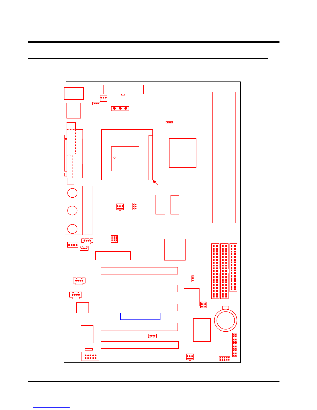
2.2 Layout of Transcend’s TS-AWE3/TS-AWH3 Motherboard
KB MOUSE
PS/2
T:Mouse
B:Keyboard
USB
USB
T:Port 1
B:Port 2
COMA
PRINTER
VGA
FAN1
JP1
Parallel Port
Game Port
POWER-FAN
FAN2
370
PGA
JP2
PWR-CONN
JP15
Intel
810DC-100
SDRAM
GMCH
810E/
SDRAM
DIMM3 (64bit 168pin SDRAM Module)
DIMM2 (64bit 168pin SDRAM Module)
DIMM1 (64bit 168pin SDRAM Module)
MODEM
CD1
CD2
AMR
COMB
JP3
PCI Slot1 (PCI1
PCI Slot2 (PCI2
PCI Slot3 (PCI3
Transcend
PCI Slot4 (PCI4
PCI Slot5 (PCI5
WOL
Intel
ICH
FWH
FAN3
JP5
JP6
JP7
83627
Winbond
FDCIDE2IDE1
Li Battery
Panel
IrDA
Connector
HARDWARE INSTALLATION 7
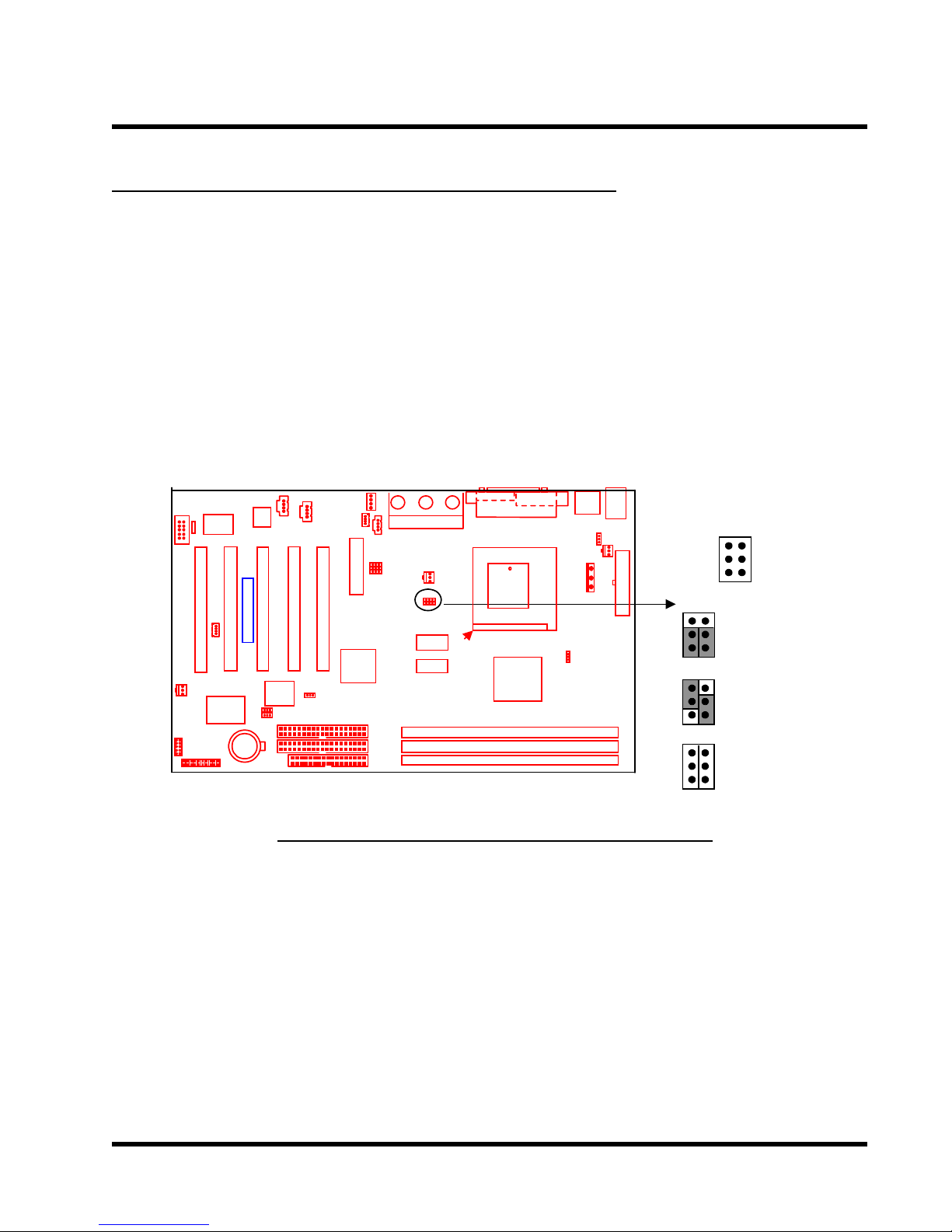
2.3 66/100/133 MHz System Configuration
The JP2 Jumper allows you to set the FSB (Front Side Bus) to either 66/100/133MHz
configuration. When you set the FSB to 66MHz, you can select a system bus frequency from
66MHz to 75MHz through “CPU Host/PCI Clock” of “Frequency/V oltage Control” in the BIOS
Setup menu (please refer to page 44). When you set the FSB to 100MHz, you can select a
system bus frequency from 100MHz to 124MHz through “CPU Host/PCI Clock” of “Frequency/
V oltage Control” in the BIOS Setup menu (please refer to page 44). When you set the FSB to
133MHz, you can select a system bus frequency from 133MHz to 150MHz through “CPU HOST
/ PCI Clock” of “Frequency / Voltage Control” in the BIOS Setup menu (please refer to page
44).
JP2
Transcend
66/100/133MHz FSB Configuration Jumper
1
5
66MHz
100MHz
133MHz
2
6

8 HARDWARE INSTALLATION
2.4 Memory Configuration
This motherboard must be installed with PC100 / PC133 SDRAM DIMM. If you install one
DIMM, place it in the DIMM1 slot. If you install two DIMMs, place them in slots DIMM1 and
DIMM2. If you install three DIMMs, you can only install single sided DIMMs onto the DIMM2
and DIMM3 slots, not double-sided DIMMs. Install memory in any combination as follows:
forebmuN
seludomyromeM
1
2
3
NOTE: This motherboard supports memory module with 8/16/32/64/128/256MB. If you
have more than one RAM module, you should install them from DIMM1 to DIMM3 in
order.
1MMID2MMID3MMID
dediS-elbuoD
dediS-elgniS/
dediS-elbuoD
dediS-elgniS/
dediS-elbuoD
dediS-elgniS/
llatsnitonoD
MMIDyna
dediS-elbuoD
dediS-elgniS/
dediS-elgniSdediS-elgniS
llatsnitonoD
MMIDyna
llatsnitonoD
MMIDyna
Transcend
3.3V Position
Unbuffered Position
168-pin Unbuffered SDRAM Module (DIMM1)
168-pin Unbuffered SDRAM Module (DIMM2)
168-pin Unbuffered SDRAM Module (DIMM3)
168Pin Memory DIMM Sockets
HARDWARE INSTALLATION 9
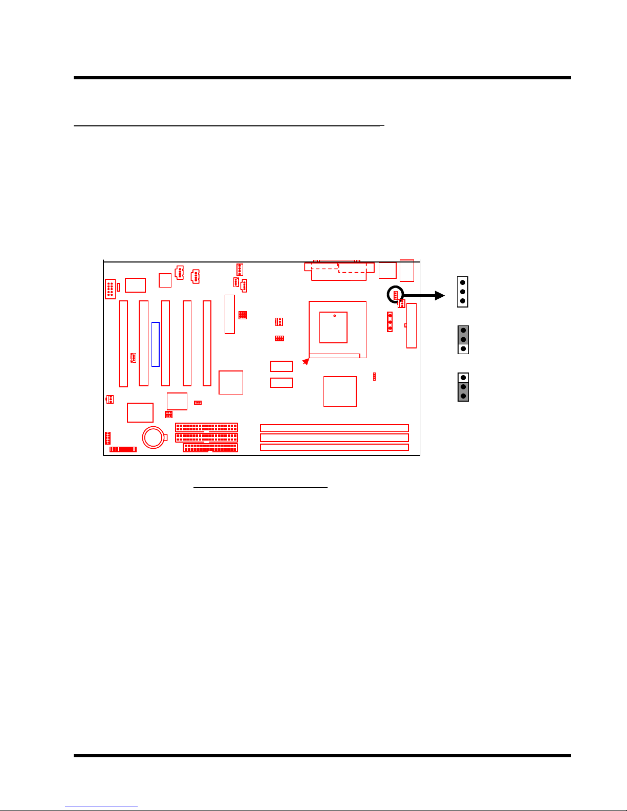
2.5 Keyboard Wake Up (3-pin KB-AWK)
This function makes the Keyboard Power Up the system. Set this jumper to “Enable” if you’d
like your Keyboard to Power Up your computer. Then, go to the”Power On Function” in the
“Integrated Peripherals” (please refer to page 35~36), and choose the setting you prefer.
JP1
1
KB-AWK
Transcend
1
Disable
Keyboard Wake Up
1
Enable
10 HARDWARE INSTALLATION
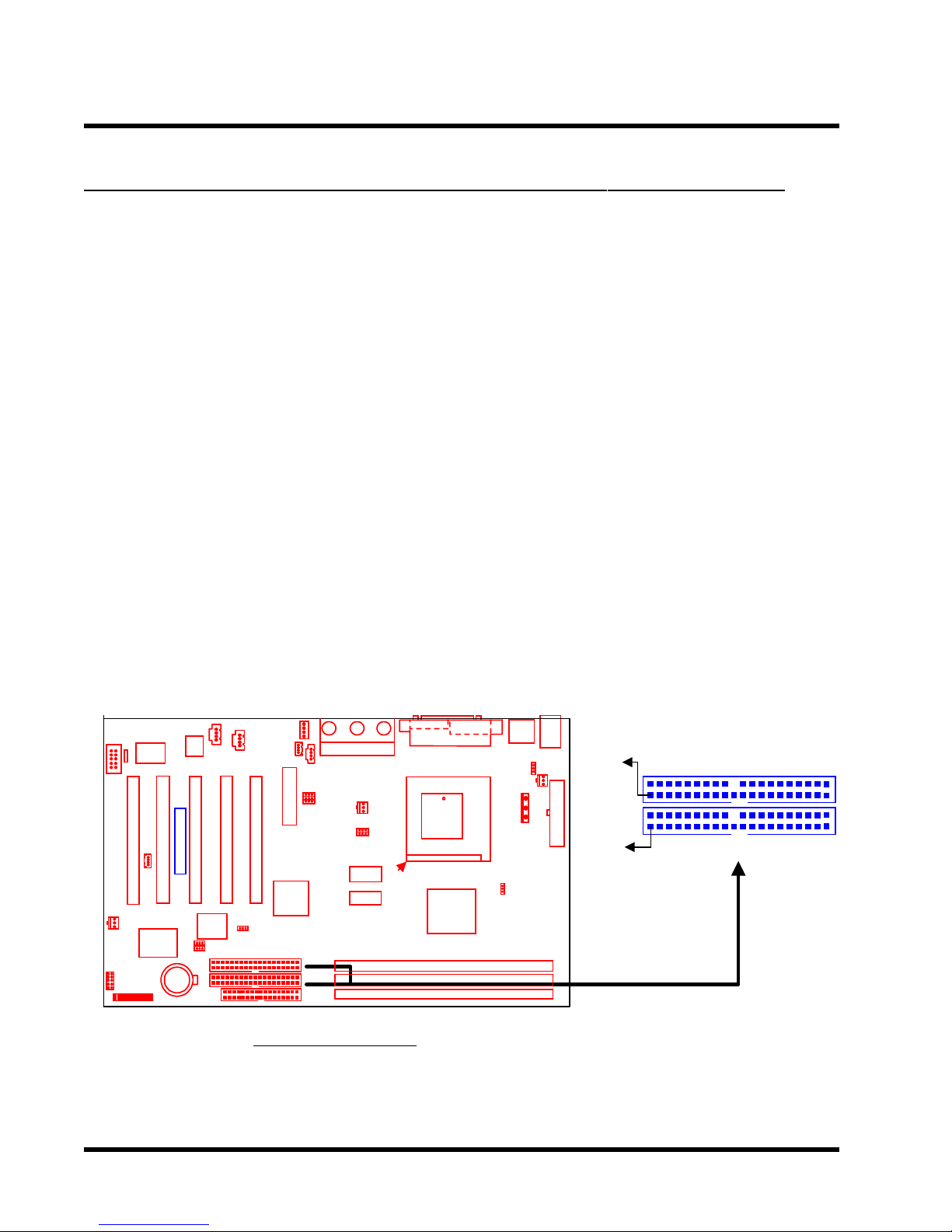
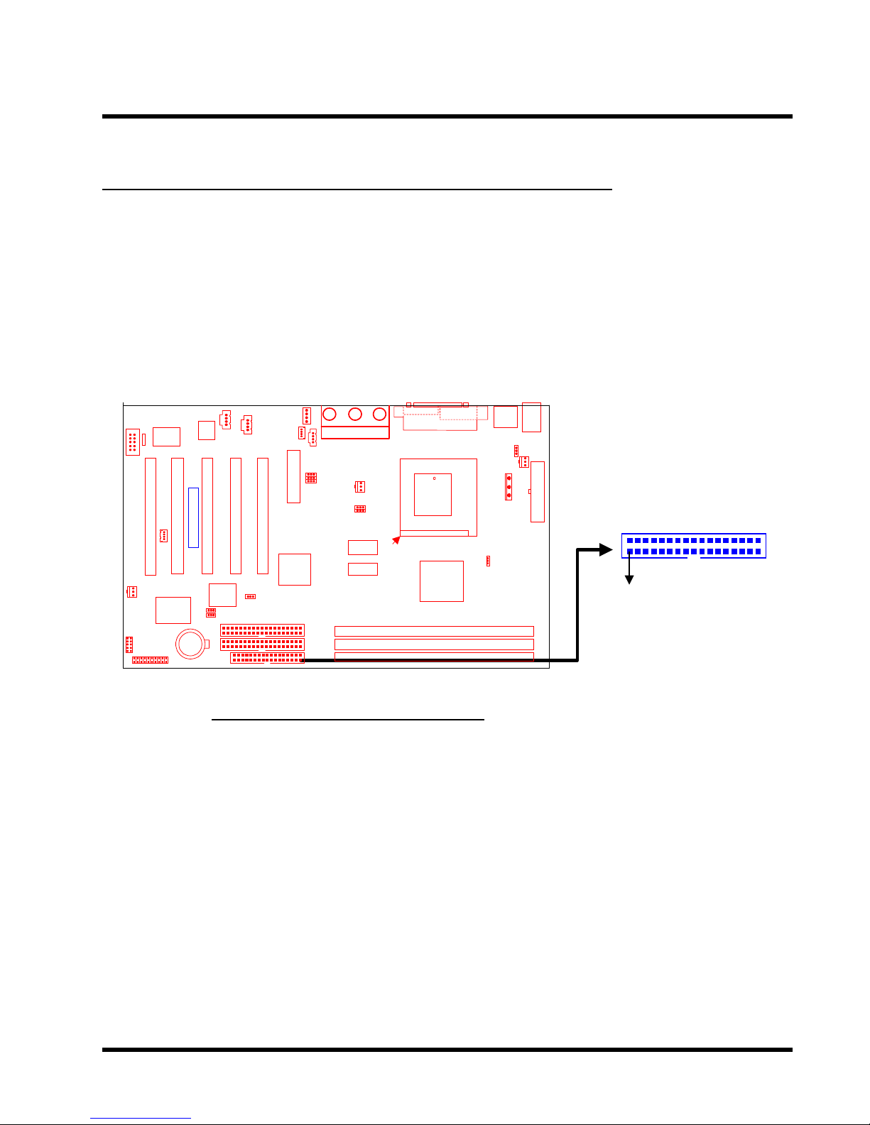
2.6 Primary / Secondary IDE Connectors (Two 40-pin IDE)
This motherboard supports two 40-pin IDE connectors marked as IDE1 (primary channel) and
IDE2 (secondary channel). Each channel supports two IDE devices, making a total of four
devices.
Connect your Hard Disk (the main one if you are using more than one) to the “Master” connector
(at the end of the cable) and connect it to IDE1 (see important note below). If your HDD
supports Ultra DMA/66, you must use an 80-wire cable, otherwise the HDD won’t be able to
reach this speed.
If you intend to operate two IDE devices from the same channel, one device must be set to
“Master” mode, the other to “Slave” mode. A Hard Disk, CD ROM or other IDE device can have
either setting, depending on device’s jumper. Please refer to the device’s manual for more
information.
NOTE: The Connectors must be attached to the IDE channels the right way round. Make
sure that the red stripe on one edge of the ribbon cable (this may be faint and could also
be a dotted line) is the nearest to PIN 1 (on the left as the motherboard is shown in the
picture below).
IDE
PIN1
IDE1
Transcend
IDE2
PIN1
Primary IDE Connector
Secondary IDE Connector
IDE Connectors
HARDWARE INSTALLATION 11
2.7 Floppy Disk Drive Connector (34-pin FDC)
This connector supports the floppy disk drive ribbon cable which is one of the items in your
motherboard package. After connecting the single end to the board, connect the two plugs at the
other end to the floppy drives. Remember, as in the last section, the red stripe on the edge of the
ribbon cable must be the nearest to PIN 1, otherwise your connection won’t work. This means it
must be on the left as the motherboard is shown below.
Transcend
Floppy Disk Drive Connector
Floppy Connector
FDC
PIN1
12 HARDWARE INSTALLATION
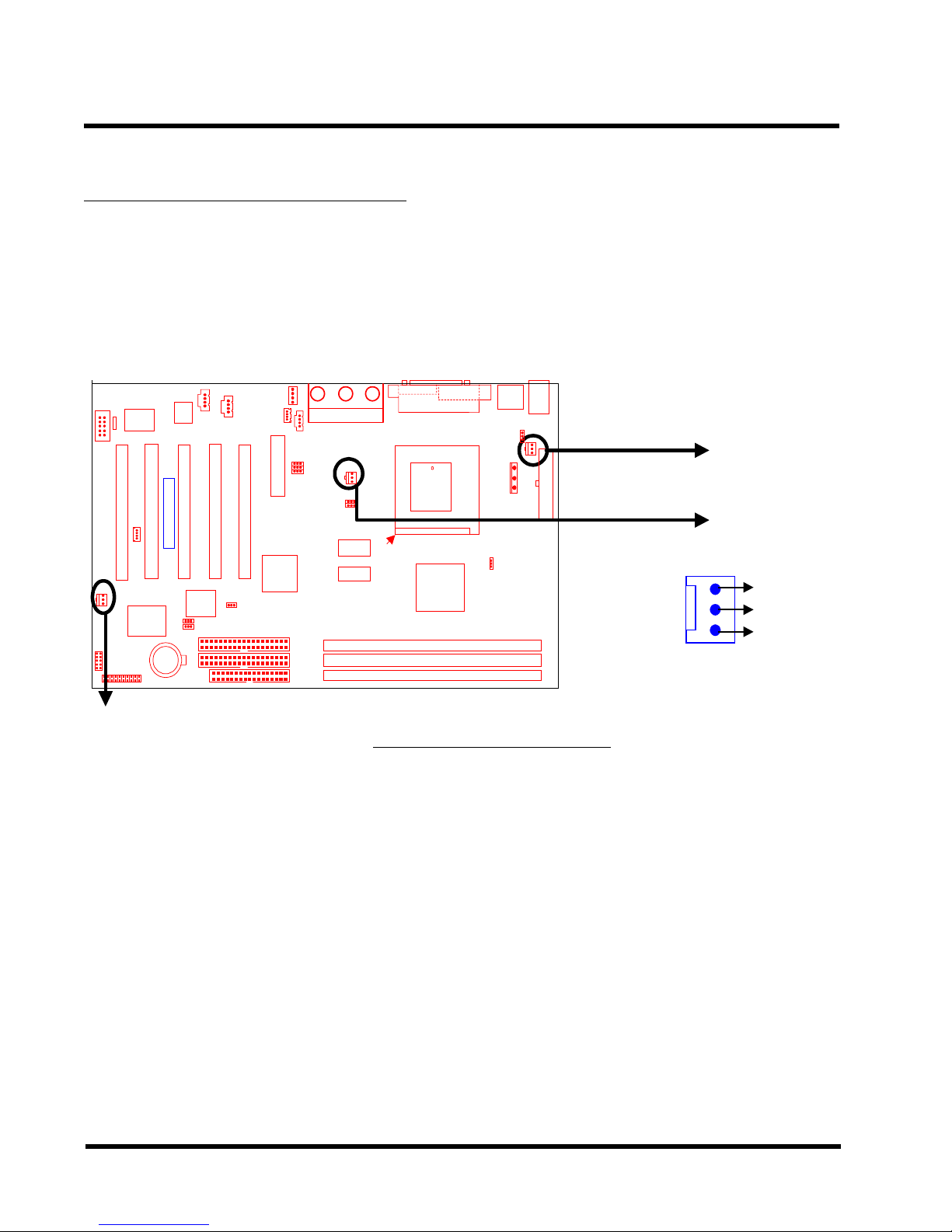
2.8 Fan Power Connectors
There are three fan power connectors on the motherboard: CPU-FAN, POWER-F AN, and CASEFAN. Each connector provides +12V power . The cables can only be attached a certain way: If
you try to put them in the wrong way , they won’t fit. These connectors support cooling fans of 500
mA (6W) or less.
CPU-FAN
Transcend
POWER-FAN
FAN
CASE-FAN
GND
+12V
Rotation
Fan Power Connectors
HARDWARE INSTALLATION 13
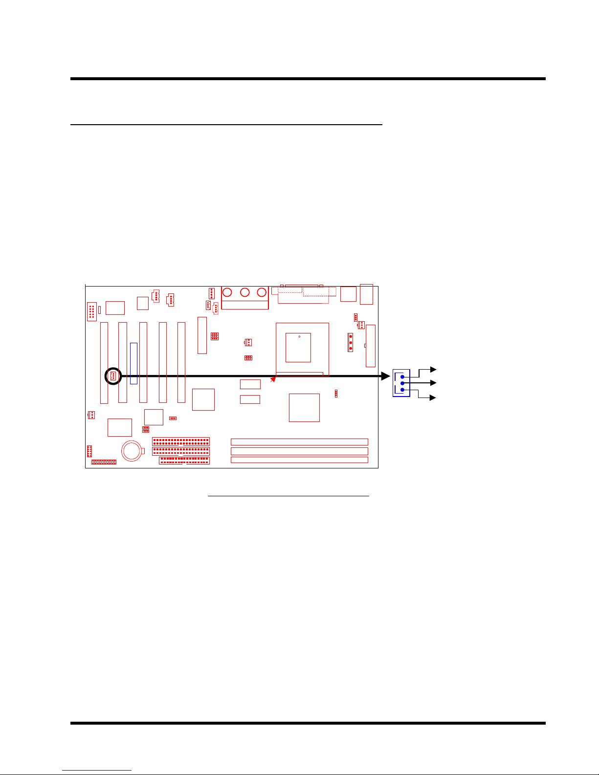
2.9 Wake-on-LAN Connector (3-pin WOL)
This connector connects to LAN cards with a Wake-on-LAN output. The system can be Powered
Up when a wakeup packet or signal is received from the LAN card.
NOTE:This function requires that the “Wake-Up by PCI & WOL” function in the “Power
Management Setup” is set to “Enabled” and that your system has an A TX power supply
with at least 720mA +5V standby power.
Transcend
WOL
+5V Standby
GND
PME
Wake-on-LAN Connector
14 HARDW ARE INSTALLATION
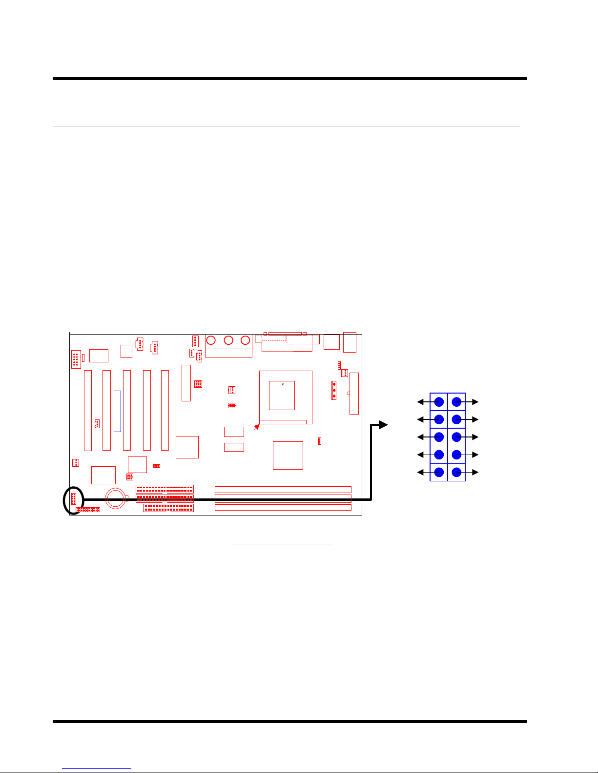
2.10 IrDA-Compliant Infrared Module Connector (10-pin IrDA)
The IrDA connector can be configured to support a wireless infrared module. With this module
and application software such as Laplink or Win95 Direct Cable Connection, users can transfer
files to or from laptops (notebooks), PDAs and printers. You must also configure the setting
through “UART Mode Select” in the “Integrated Peripherals” (please refer to page 34) to select
“IrDA”. Connect the Standard IR (SIR) device to the onboard SIR connector according to the pin
definitions. An optional Consumer Infrared (CIR) set connects to the CIR and SIR connectors
simultaneously for both wireless transmitting and remote control functions through one external
infrared module.
Transcend
IrDA Connector
+5V
NC
IRRX
GND
IRTX
IrDA
CIRSIR
12
NC
CIRRX
5VSB
NC
NC
910
HARDWARE INSTALLATION 15
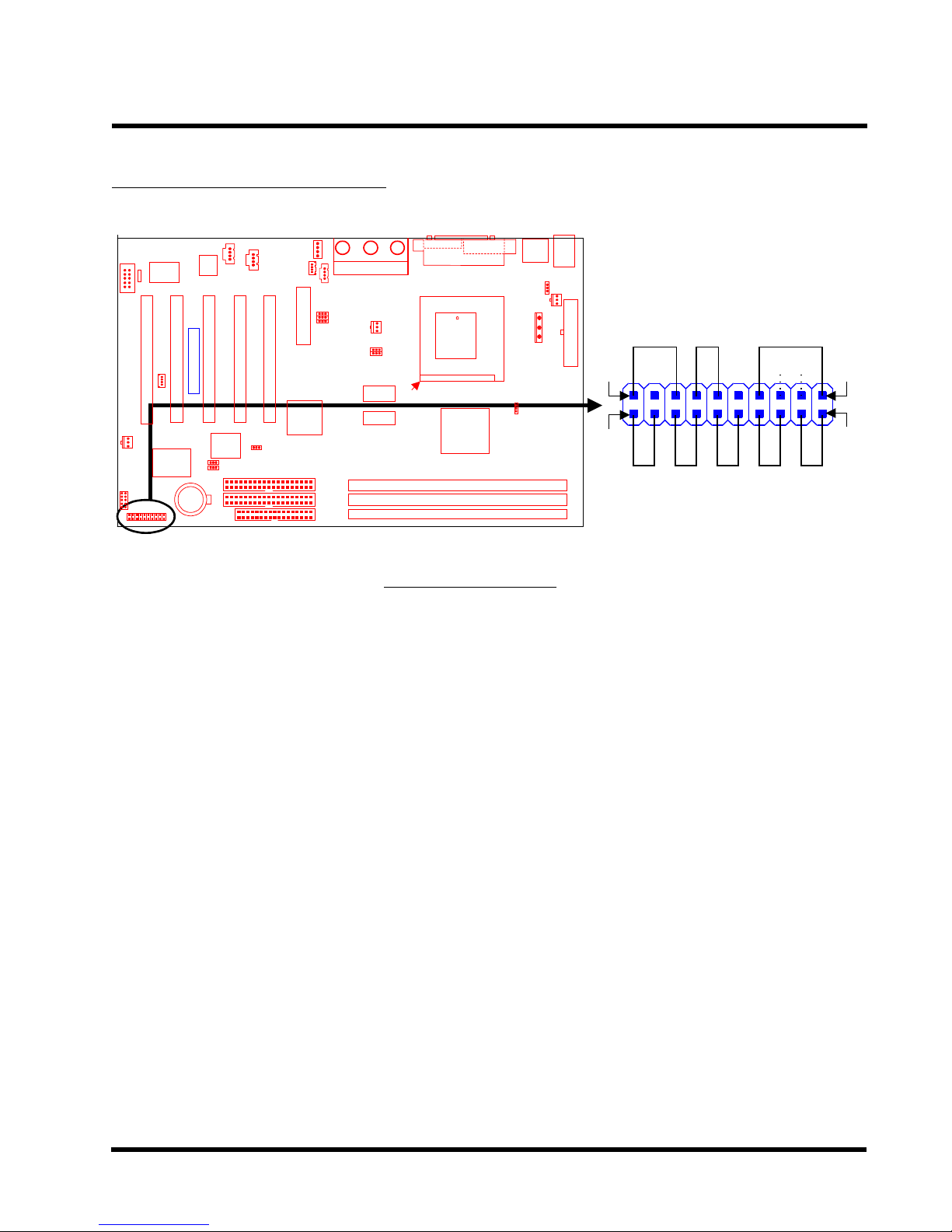
2.11 Panel Connectors
Transcend
Panel Connector
Power LED Lead (3-pin POWER LED)
This 3-pin connector attaches to the power LED.
Pin1 : +5V
Pin3 : NC
POWER LED
1 19
++
+++
S_LED HDD_LED NC RESET SOFT_OFF
KEY LOCK
SPEAKER
202
Pin5 : GND
Keylock Lead (2-pin KEYLOCK)
Use the keylock to enable or disable the Keyboard.
Pin7 : KEYLOCK
Pin9 : GND
Speaker Lead (4-pin SPEAKER)
This 4-pin connector connects to the case-mounted speaker.
Pin13 : +5V
Pin15 : GND
Pin17 : NC
Pin19 : SPK
 Loading...