

Transcend TS-AVE3 User Manual

TS-AVE3
USER’S MANUAL
Intel
®
Socket 370 Celeron
TM
/
Pentium® III FC-PGA Series
Transcend
Your Supplier, Your Partner,
Your Friend.

TS-AVE3 Motherboard
Supporting Intel ® Socket 370 CeleronTM/Pentium IIITM FC-PGA Series Processor
66/100/133 MHz Front Side Bus Frequency
AGP 4X
VIA® Apollo Pro 133A Chipset
Welcome !!
Congratulations on your purchase of this great value motherboard, with its range of special
features and innovative onboard functions, built around the advanced architecture of the new
VIA® Apollo Pro 133A Chipset. More details to follow later in this manual.
Our Website
Please come and visit us at our website on http://www.transcendusa.com/ . You’ll find plenty
of interesting information about this and many other quality Transcend products.
Your User’s Manual
This User’s Manual is designed to help end users and system manufacturers to set up and
install the motherboard. All of the information within has been carefully checked for accuracy .
However, Transcend Information, Inc. (hereafter referred to as “Transcend”) carries no
responsibility or liability for any errors or inaccuracies which this manual may contain. This
includes references to products and software. In addition, the information and specifications
are subject to change without prior notice.
Disclaimer
Transcend provides this manual “as is” without any warranty of any kind, either expressed or
implied, including - but not limited to - the implied warranties, conditions of merchantability or
fitness for a particular purpose. Transcend, its management, employees, distributors and
agents are in no way liable for any indirect special, incidental or consequential damages,
including loss of profits, loss of business and the like. This is even if Transcend has been
advised of the possibility of such damages arising from any defect or error in this manual or
product.
Trademarks
All brands, product names and trademarks mentioned in this document are the property of
their respective owners or companies and are used solely for identification or explanation. It
is Transcend policy to respect all product rights.
Copyright
This manual may not, in whole or in part, be photocopied, reproduced, transcribed, translated
or transmitted, in whatever form or language, without the written consent of the manufacturer,
except for copies retained by the purchaser for personal archiving purposes.
Manual Version: 1.1
Release Date: November, 2000
Copyright © November 2000 Transcend Information, Inc.

T able of Contents
CHAPTER 1 INTRODUCTION 1
1.1 Essential Handling Precautions ......................................................................................1
1.2 Checklist: Hardware Required for Setup .......................................................................2
1.3 Package Contents .................................................................................................. 2
1.4 Specifications and Features ...........................................................................................3
CHAPTER 2 HARDWARE INSTALLATION 5
2.1 Transcend’s TS-AVE3 Motherboard ............................................................... 5
2.2 Layout of Transcend’s TS-AVE3 Motherboard ................................................. 6
2.3 CPU Installation ............................................................................................ 7
2.4 66/100/133MHz System Configuration ........................................................ 10
2.5 Memory Configuration ................................................................................... 10
2.6 Primary/Secondary IDE Connectors ............................................................. 11
2.7 Floppy Disk Drive Connector .......................................................................... 12
2.8 Fan Power Connectors ............................................................................... 12
2.9 Wake-on-LAN Connector ............................................................................ 13
2.10 IrDA-Compliant Infrared Module Connector .................................................. 13
2.11 Panel Connectors ....................................................................................... 14
2.12 Power Connector ....................................................................................... 16
2.13 External Back Panel I/O Ports ..................................................................... 16
2.14 Using JPS to clear CMOS Jumper........................................................................... 17
2.15 Onboard Audio Setting .............................................................................. 18
2.16 Internal Audio Connectors ...................................................................................... 19
2.17 Internal USB Port Connector
................................................................................ 20

CHAPTER 3 BIOS SETUP 21
3.1 BIOS Setup.................................................................................................. 21
3.2 The Main Menu ........................................................................................... 21
3.3 Standard CMOS Features............................................................................. 23
3.4 Advanced BIOS Features............................................................................. 26
3.5 Advanced Chipset Features .......................................................................... 29
3.6 Integrated Peripherals ........................................................................... 32
3.7 Power Management Setup......................................................................... 35
3.8 PnP/PCI Configurations ................................................................................ 38
3.9 PC Health Status................................................................................... 41
3.10 Frequency/Voltage Control ........................................................................... 42
3.11 Load Fail-Safe Defaults ............................................................................. 42
3.12 Load Optimized Defanlts.............................................................................. 43
3.13 Supervisor Password ................................................................................ 43
3.14 User Password.................................................................................... 44
3.15 Save & Exit Setup................................................................................... 44
3.16 Exit Without Saving................................................................................... 44
CHAPTER 4 BIOS UPGRADE 45
4.1 How to Check Your BIOS File Name and Version .......................................... 45
4.2 How to Download the Correct BIOS File from Our Web Site.............................45
4.3 How to Upgrade Your Motherboard BIOS .................................................... 46

INTRODUCTION 1
CHAPTER 1 INTRODUCTION
1.1 Essential Handling Precautions
IMPORTANT. Read this page before unpacking your motherboard!
• Power Supply
Be careful! Always ensure that the computer is disconnected from the power supply when
working on the motherboard and its components.
• Static
Static electricity may cause damage to the delicate integrated circuit chips on your motherboard.
Before handling the motherboard outside of its protective packaging, ensure that there is no
static electric charge in your body . To avoid this risk, please observe these simple precautions
while handling the motherboard and other computer components:
1. If possible, wear an anti-static wrist strap. This fits around your wrist and is connected to
a natural earth ground.
2. Touch a grounded or anti-static surface, or a metal fixture such as a pipe or the chassis of
your system, before touching the motherboard.
3. When you have removed the motherboard from its anti-static packaging, try to hold it only
by the edges, without touching any components.
4. Avoid contacting the components on add-on cards, motherboards, and modules with the
golden fingers (gold-colored connectors) which plug into the expansion slots.
5. It is safest to handle system components only by their mounting brackets.
6. Keep components which are not connected to the system in the anti-static packaging
whenever possible.
These precautions help to reduce the risk of static build-up and ensure any static discharge is
harmless to your equipment.
••
• Battery Replacement
••
The battery which holds the system settings memory on your motherboard should not require
replacement for at least five years, and probably much longer . In picture 2.2, it is located near
the bottom right hand corner.

2 INTRODUCTION
Please replace your battery only with the same type, or a similar type recommended by the
manufacturer. If the battery is replaced incorrectly, there is a risk of a short circuit or explosion.
Used batteries should disposed of according to the manufacturer’s instructions.
••
• Electric Screwdrivers
••
To reduce the risk of damage to the motherboard due to excessive torque, avoid setting
electric screwdrivers above 7.5 kg/cm.
1.2 Checklist: Hardware Required for Setup
It is advisable to have all of these items of hardware available before you unpack your
motherboard from its anti-static packaging and start building your system.
- Computer case and chassis with appropriate power supply.
- Monitor.
- Socket 370 Central Processing Unit (CPU).
- DIMM memory module.
- PS/2 or USB Keyboard.
- PS/2 or USB Mouse.
- Hard Disk Drive.
- Floppy Disk Drive.
- CD-ROM Drive.
- (Optional) External Peripherals: printer, speakers, plotter, modem.
- (Optional) Internal Peripherals: modem, LAN cards.
1.3 Package Contents
This motherboard package should contain the following items. Please check them as soon as
you unpack. If you find any damaged or missing items, please contact your retailer.
- TS-AVE3 motherboard
- 1 x CD-ROM
- 1 x FDD cable
- 1 x Ultra DMA/66 cable
- User ’s Manual
- 1 x External USB connector (Optional)

INTRODUCTION 3
1.4 Specifications and Features
• •
• CPU
• •
- Supports Intel Socket 370 Celeron
- Supports Intel Pentium III FC-PGA
• •
• Chipset
• •
-TS-AVE3: VIA 694X/686A AGPset
-TS-AVE3/B: VIA 694X/686B AGPset
• •
• DRAM Memory
• •
- Supports Synchronous DRAM
- Supports Virtual Channel Memory
- 3 x slots for 168-pin DIMM module
- 8MB~1.5GB memory size
- 8/16/32/64/128/256/512MB SDRAM DIMM
TM
- Supports ECC
- 64 data bits structure only
- PC100/PC133 SDRAM compliant
• •
• I/O BUS Slot
• •
- 1 x AGP slot
- 5 x Master/Slave PCI slots (PCI 2.1 compliant)
- 1 x ISA slot
- 1 x ARM slot (Share with ISA slot)
• •
• I/O Functions
• •
- Supports PIO Mode 3,4 ATAPI devices and Ultra DMA/33/66/(100,For 686B Only)
- Supports 2 high speed UART 16550 COM ports
- Supports SPP/EPP/ECP LPT port
- Supports 1.44/2.88 MB floppy drive
- Supports PS/2 Mouse and PS/2 Keyboard
- Supports IrDA port
- Supports 4 Universal Serial Bus (USB) ports

4 INTRODUCTION
•
Award BIOS
- Support Plug-and-Play, PC98
- Support ACPI, APM, DMI and Green Feature
- Easy BIOS Recovery
•
Wake Up Features
- Supports Wake-on-LAN function
- Remote Ring Wake Up
- Time Wake Up
•
PCB Dimensions
- ATX form factor, 4-layer PCB, 19cm x 30.5cm (8 inch x 12 inch)
•
Switching Voltage Regulator
- Intel VRM 8.4 compliant
•
Other Features
- Year 2000 compliant
- Anti-Virus Boot up
- System voltage monitors for CPU Vcore, +2.5, +3.3V, +5V and +12V
- CPU temperature monitor
- System temperature monitor
- F AN speed monitor
HARDWARE INSTALLATION 5
g
CHAPTER 2 HARDWARE INSTALLATION
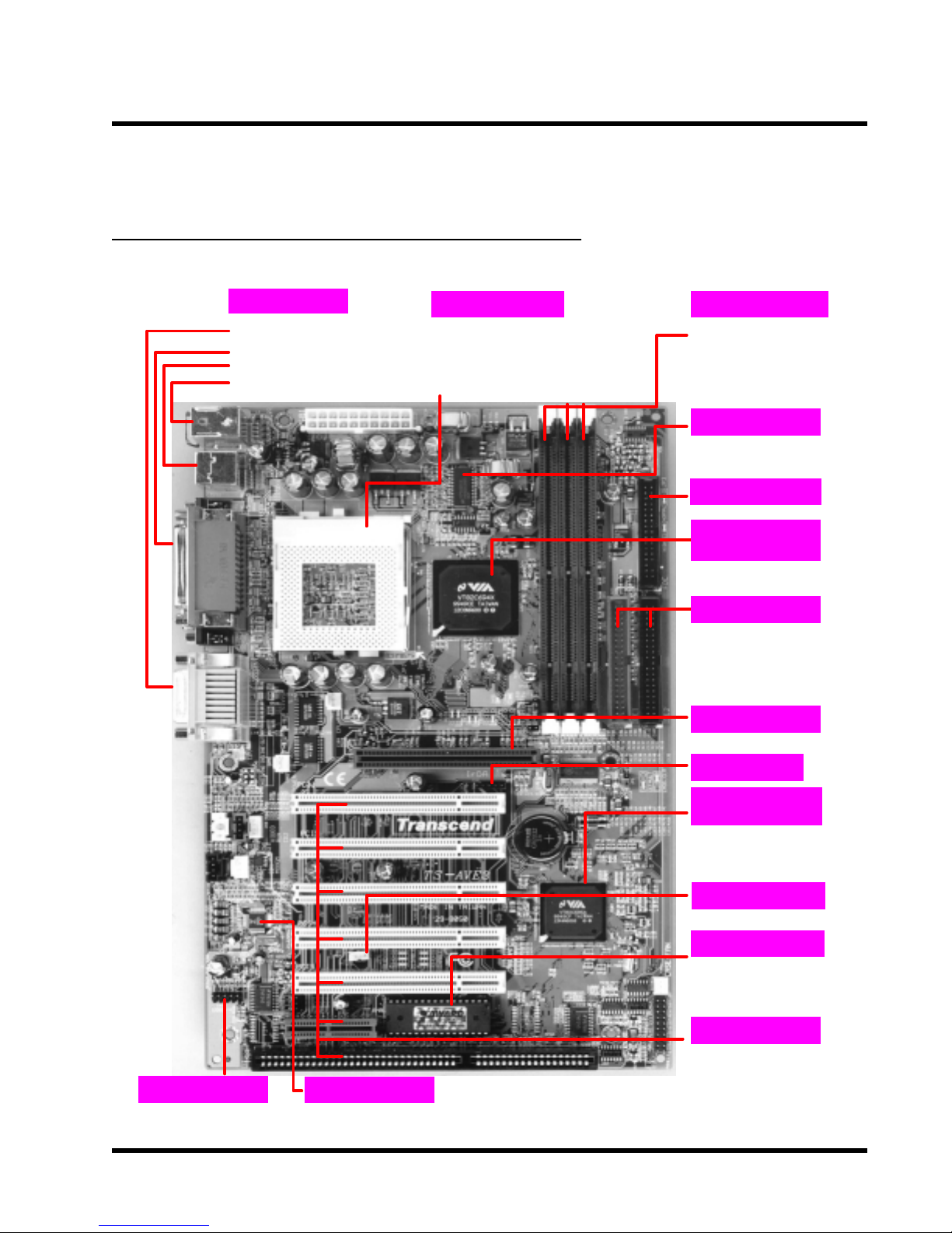
2.1 Transcend’s TS-AVE3 Motherboard
I/O Port
I/O Port
General MIDI Port & Audio Jack
·
(Line-In, Line-Out, MIC-In)
·
x COM Ports & 1 x Parallel Port
2
2 x USB Ports
·
PS/2 KB Port & PS/2 Mouse Port
·
CPU
Intel® CeleronTM Socket 370 PPGA
·
CPU 300A~533 MHz (FSB 66MHz)
Intel® Pentium® III Socket 370 FC-PGA
·
CPU 533A~633+ MHz (FSB 66MHz)
CPU 500~933+MHz (FSB 100/133MHz)
·
·
Memory
3 x 168 -pin DIMM Sockets
·
8MB~1.5GB SDRAM
·
Switching Reg.Switching Reg.
Intel® VRM 8.4 Compliant
·
FDD Connector
VIA Apollo
Pro 133A Chipset
Supports 66/100/133MHz FSB
·
·
PCI IDE Connector
Bus Master
·
·
PIO Mode 3/4
·
·
DMA Mode 2
·
·
Ultra DMA 33/66
·
·
AGP Connector
·
·
Supports AGP1X/2X/4X
IrDA
External USB
Connector
·
·
2 x USB Ports
·
·
AC97 V2.1 Audio CODEC
AC97 CODEC
VIA 686A Super
South Brid
·
Supports System Health
Monitor
Build-In Super I/O
·
·
WOL HeaderWOL Header
Wake-on-LAN
·
·
Flash EEPROMFlash EEPROM
Award BIOS
·
·
PnP,DMI
·
·
ACPI compliant
·
·
Expansion SlotsExpansion Slots
5 x PCI Slots
··
1 x AMR Slot
··
1 x ISA Slot
·
(Shared with AMR)
e
6 HARDWARE INSTALLATION
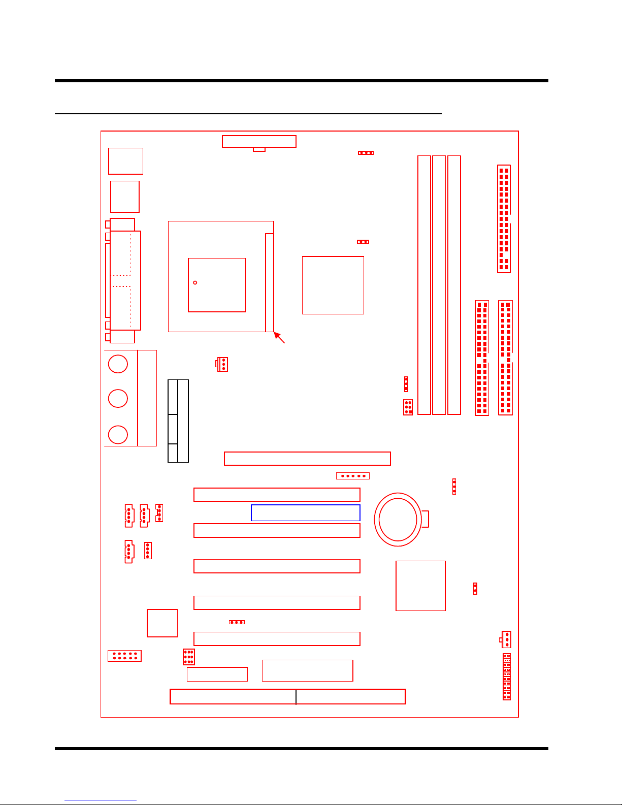
2.2 Layout of Transcend’s TS-AVE3 Motherboard
KB MOUSE
PS/2
T:Mose
B:Keyboard
USB
USB
T:Port 1
B:Port 2
ATX Power Connector
JP3
VIO
COMB
Printer
COMA
Parallel Port
Game Port
GAME
LINE-IN LINE-OUT
MIC
AUX
CD2
VIDEO
370
PGA
CPU-FAN
PCI Slot 1
PCI Slot 2
VIA
694X
Chipset
AGP Slot
IrDA
Transcend
TS-AVE3
JP7
Intel/Cyrix
JP2
66/100
100/133
JP4
Li Battery
DIMM1
DIMM2
DIMM3
IDE1
CMOS_CLR
JP5
FDC
IDE2
CD1
MODEM
AC97
CODEC
AUDIO
CN14
USB 3/4
JP6
AMR Slot
PCI Slot 3
PCI Slot 4
WOL
PCI Slot 5
ISA Slot
2M-bit Flash
BIOS(EEPROM)
VIA
686A
Chipset
KB-AWK
JP1
CASE-FAN
Panel
Connector

HARDWARE INSTALLATION 7
2.3 CPU (Central Processing Unit) Installation
So far you have familiarized yourself with the handling precautions, checked you have all of
the necessary hardware for building your system, inspected the motherboard package contents
and looked at the layout of the motherboard. This chapter will take you step by step through
the process of installing the different hardware devices onto it.
Caution
1. Remember to always make sure the system power is off before installing or removing
any devices.
2. Don’t forget the static electricity precautions.
3. Be careful ! Inserting hardware onto your motherboard incorrectly can damage it.
The motherboard has a ZIF Socket 370 which houses the CPU. A fan is necessary for the
CPU to prevent overheating. If there is no fan on it, please purchase one before you turn on
your system.
WARNING! Be sure that sufficient air circulation is available across the processor’s
passive heatsink. Without sufficient circulation, the processor could overheat and
damage both the processor and the motherboard. You may install an auxiliary fan, if
necessary.
Please follow the steps below to install the CPU:
Step 1:
To install the CPU, first turn off your system and remove its cover. Locate the ZIF socket and
open it by first pulling the lever sideways away from the socket then upwards to a 90-degree
right angle. Insert the CPU in the correct direction, you should have a CPU fan to cover the face
of the CPU. With the added weight of the CPU fan, no force is required to insert the CPU. Once
completely inserted, close the socket’s lever while holding down the CPU.
8 HARDWARE INSTALLATION
(
)
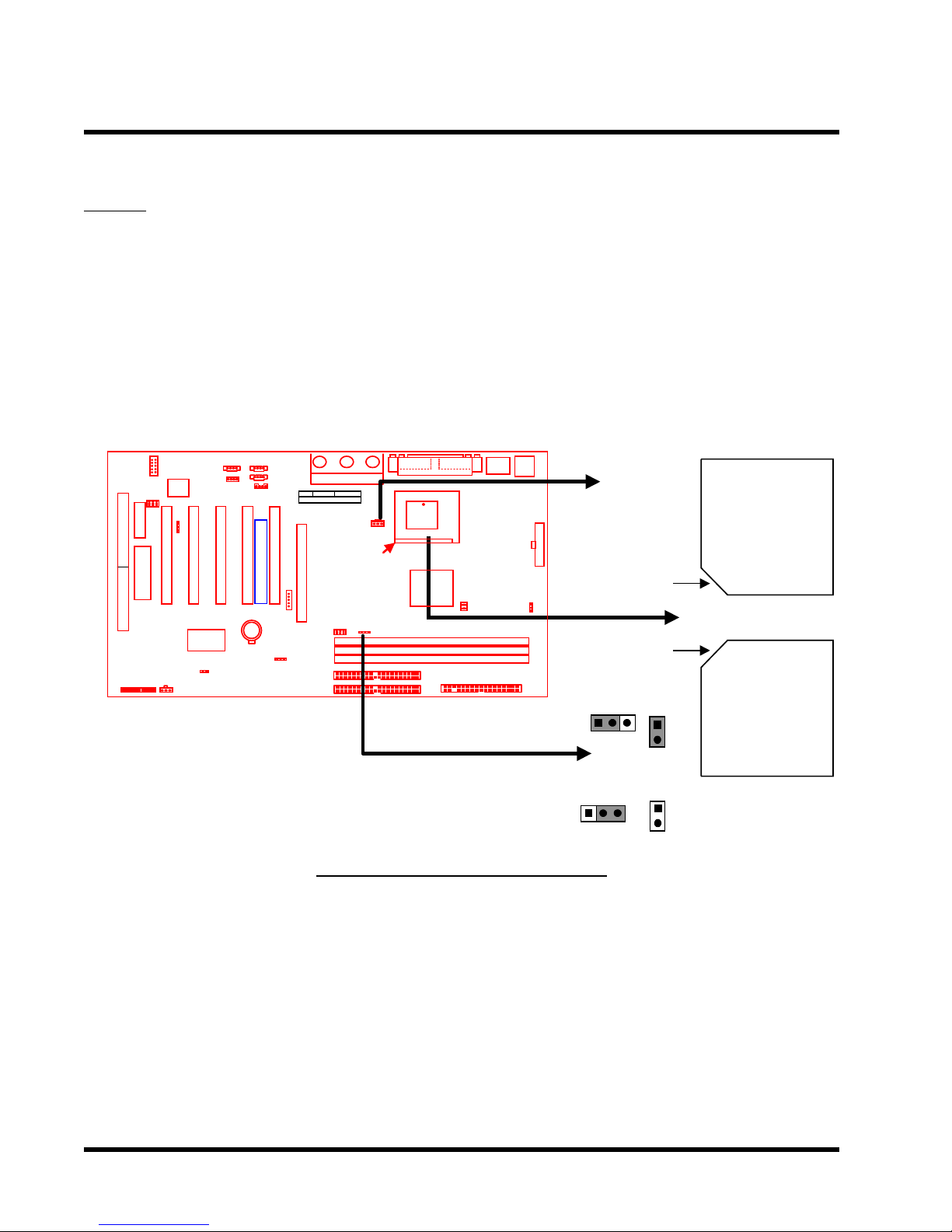
Step 2:
Next, according to the CPU type you install, short JP7 and set JP2 to short pin1 & pin2 (for an
Intel ® Celeron
TM
or Pentium ® III FC-PGA series CPU), or open JP7 and set JP2 to short pin2
& pin3 (for a Cyrix Joshua series CPU). Connect the CPU’s fan cable to the CPU-F AN connector
indicated on the diagram below. Ensure that the cable is connected correctly! It will be obvious
which way it fits.
CPU_FAN
Socket
Transcend
370 CPU
(Top View)
Notch
Notch
INTEL
1
JP2
JP7
Socket
370 CPU
Bottom View
Socket 370 CPU Installation
CYRIX
1
JP2
JP7
HARDWARE INSTALLATION 9
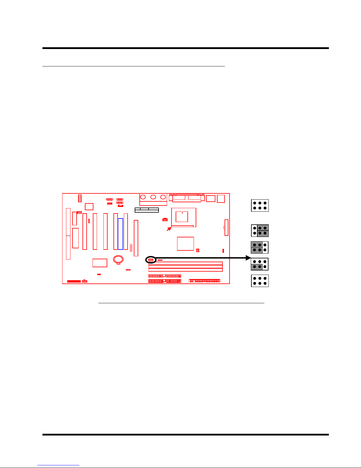
2.4 66/100/133MHz System Configuration
The jumper (JP4) allows you to set the FSB (Front Side Bus) for 66, 100 or 133MHz configuration.
When you set the FSB to 66MHz, you can select a system bus frequency from 66MHz to 95MHz
through “CPU Host/PCI Clock” in “Frequency/V oltage Control” (Please refer to page 46). When
you set the FSB to 100MHz, you can select a system bus frequency from 100MHz to 124MHz
through “CPU Host/PCI Clock” in “Frequency/V oltage Control” (Please refer to page 46) When
you set the FSB to 133MHz, you can select a system bus frequency from 124MHz to 150MHz
through ”CPU Host/PCI Clock” in “Frequency/Voltage Control” (Please refer to page 46) .
NOTE :If you are not familar with this feature, we recommend you set this jumper to
“AUTO”.
JP4
66/100/133MHz
1
Transcend
AUTO
66MHz
100MHz
133MHz
66/100/133MHz FSB Configuration Jumper
10 HARDWARE INSTALLATION
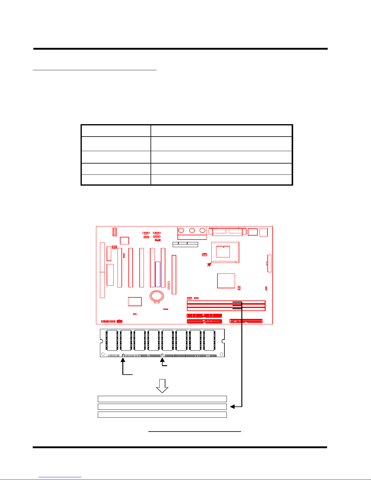
2.5 Memory Configuration
This motherboard must be installed with DIMMs (Dual Inline Memory Modules). The DIMMs
must be 3.3 Volt synchronous DRAM modules. The VIA Apollo Pro 133A chipset supports
PC100, PC133 and Virtual Channel Memory (VCM). It also supports ECC (Error Checking
and Correcting) modules. Y ou can install memory in any combination as follows:
DIMM Location
DIMM1
DIMM2
DIMM3
Total Memory
SDRAM 8,16, 32, 64,128, 256, 512MBytes
SDRAM 8,16, 32, 64,128, 256, 512MBytes
SDRAM 8,16, 32, 64,128, 256, 512MBytes
1.5GBytes (max.)
168-pin DIMM
NOTE: Different types of DRAM modules should not be installed on one motherboard at
the same time.
Transcend
3.3V Position
Unbuffered Position
168Pin SDRAM Module (DIMM1)
168Pin SDRAM Module (DIMM2)
168Pin SDRAM Module (DIMM3)
168Pin DIMM Sockets
HARDWARE INSTALLATION 11
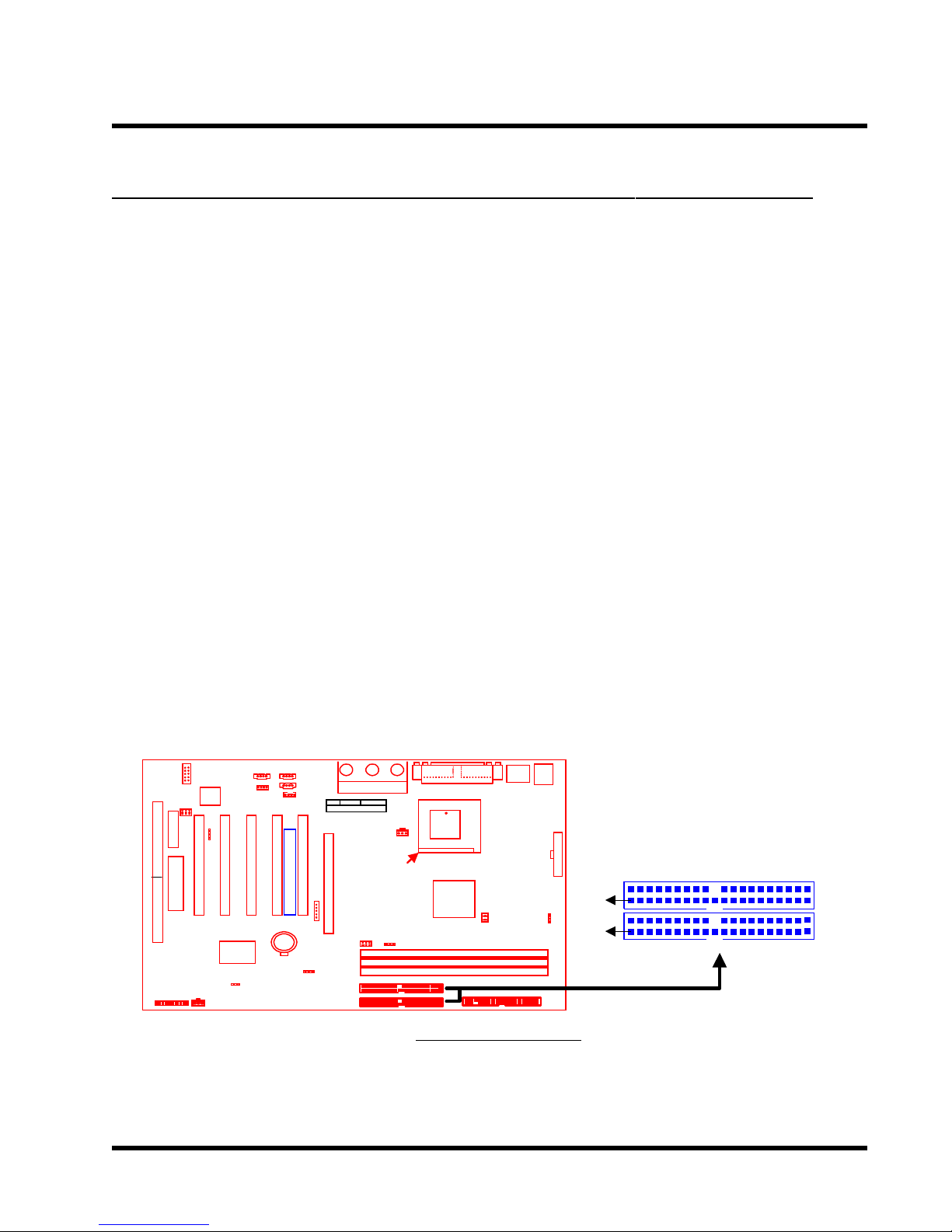
2.6 Primary / Secondary IDE Connectors (Two 40-pin IDE)
This mainboard supports two 40-pin IDE connectors marked as IDE1 (primary IDE channel)
and IDE2 (secondary IDE channel). Each channel supports two IDE devices, making a total of
four devices. Connect your Hard Disk (the main one if you are using more than one) to the
“Master” connector (at the end of the cable) and connect it to the IDE1 (see important note
below). If your HDD supports UltraDMA/66, you must use an 80-wire cable, otherwise the
HDD won’t be able to reach this speed.
If you intend to operate two IDE devices from the same channel, one device must be set to
“Master” mode, the other to “Slave” mode. A Hard Disk, CD ROM or other IDE device can
have either s e tting, depending on device’s jumper. Please refer to the device’s manual for
more information.
NOTE: The connectors must be attached to the IDE channels the right way round.
Make sure that the red stripe on one edge of the ribbon cable (this may be faint and
could also be a dotted line) is the nearest to PIN1 (on the left as the motherboard is
shown in the picture below).
Note: Orient the red
stripe to Pin1
Transcend
Secondary IDE Connector
PIN1
PIN1
Primary IDE Connector
IDE1
IDE2
IDE Connectors
12 HARDWARE INSTALLATION
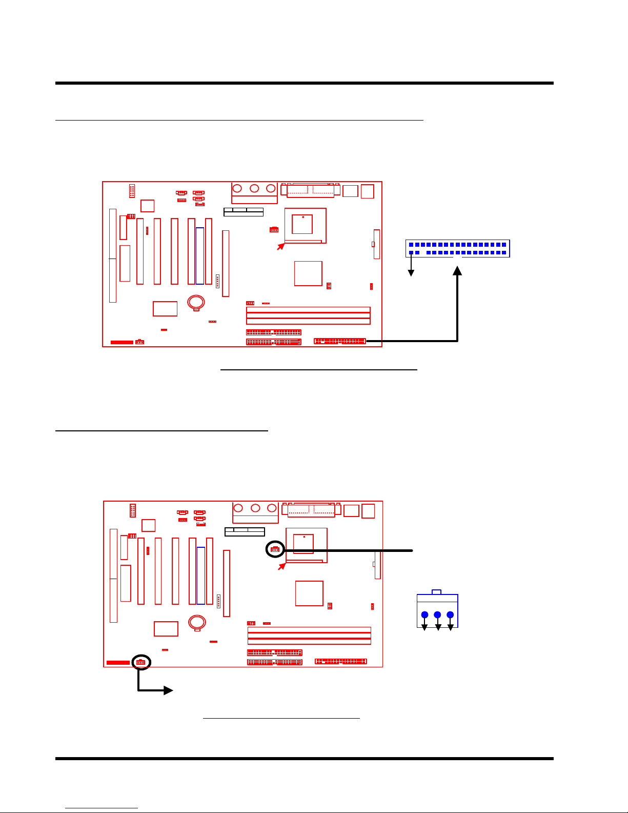
2.7 Floppy Disk Drive Connector (34-pin FDC)
This connector supports the provided floppy disk drive ribbon cable. After connecting the
single end to the board, connect the two plugs on the other end to the floppy drives.
Note: Orient the red
stripe to Pin1
Transcend
Floppy Disk Drive Connector
Floppy Drive Connector
FDC
PIN1
2.8 Fan Power Connectors
There are two fan power connectors on the mainboard: the CPU-FAN and the CASE-F AN. Each
connector provides +12V power. Make sure they are in the right orientation, or they may cause
damage. These connectors support cooling fans of 500 mA (6W) or less.
Transcend
CASE-FAN
Fan Power Connectors
CPU-FAN
FAN
Rotation
+12V
GND
HARDWARE INSTALLATION 13
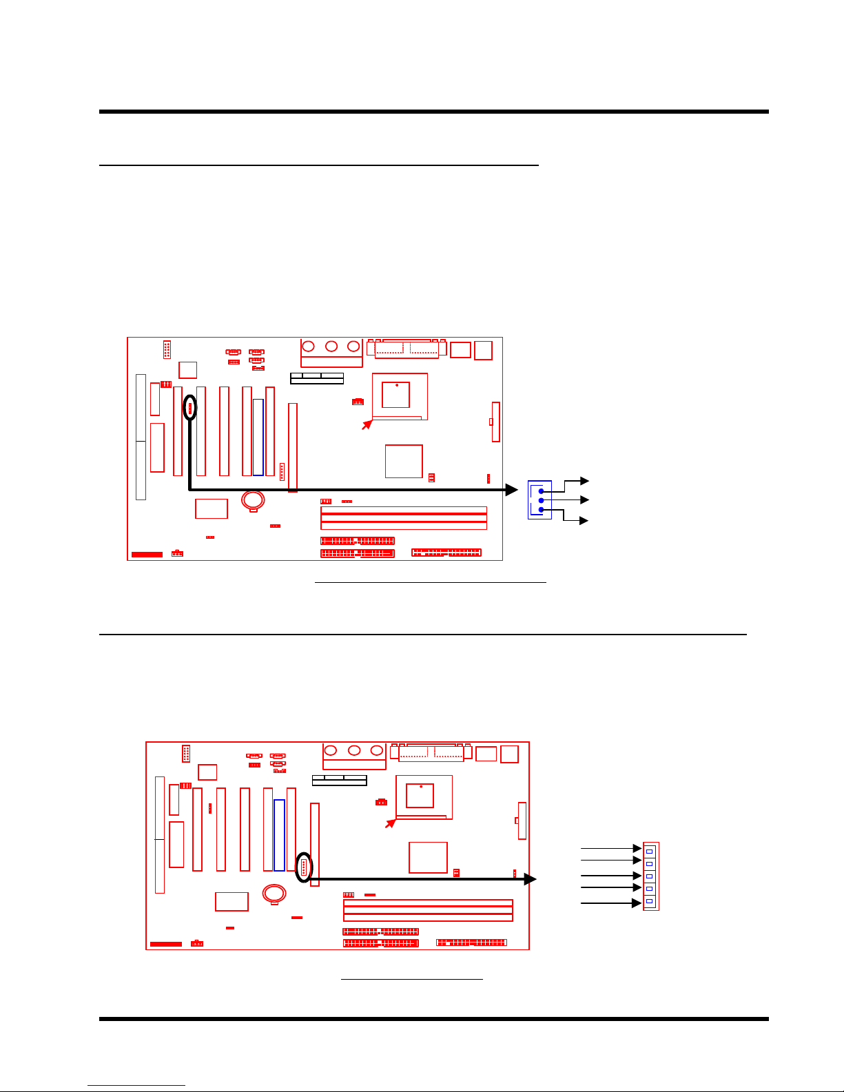
2.9 Wake-on-LAN Connector (3-pin WOL)
This connector connects to LAN cards with a Wake-on-LAN output. The system can be Power
up when a wakeup packet or signal is received from the LAN card.
NOTE: This function requires that the “LAN Wake Up” function in the POWER MANAGEMENT
SETUP is set to “Enabled” and that your system has an A TX power supply with at least
720mA +5V standby power.
Transcend
WOL
+5 Volt Standby
GND
PME
Wake-On-LAN Connector
2.10 IrDA-Compliant Infrared Module Connector (5-pin IrDA)
The IrDA connector can be configured to support a wireless infrared module. With this module
and application software such as Laplink or Win95 Direct Cable Connection, the user can
transfer files to or from laptops(notebooks), PDAs and printers.
Transcend
IrDA
+5V
NC
IRRX
GND
IRTX
IrDA Connector
1
5
14 HARDWARE INSTALLATION
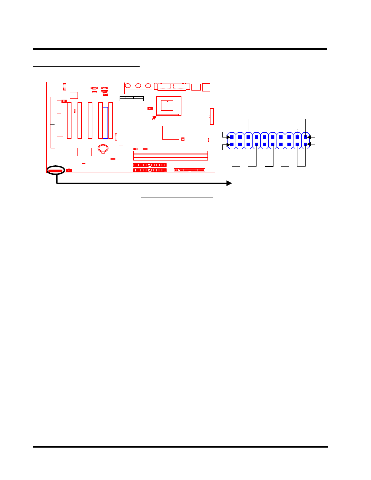
2.11 Panel Connectors
Transcend
Panel Connectors
Power LED Lead (3-pin POWER LED)
This 3-pin connector attaches to the power LED.
Pin1 : +5V
Pin3 : NC
Pin5 : G ND
Speaker Lead (4-pin SPEAKER)
This 4-pin connector connects to the case-mounted speaker.
POWER LED
1
++
++
2
S_LED HD_LED RESET SOFT_OFF
SLEEP
SPEAKER
19
20
Pin13 : +5V
Pin15 : GND
Pin17 : NC
Pin19 : SPK
Suspend Mode LED Lead (2-pin S_LED)
The S_LED will light when the suspend system is in mode works.
Pin2 : +5V
Pin4 : G ND
Harddisk LED Lead (2-pin HD_LED)
This 2-pin connector connects to the LED of the hard disk. The LED lights up when the HDD is
active.
Pin6 : +5V
Pin8 : G ND
 Loading...