

Transcend TS-AVD1 User Manual

TS-AVD1
USER’S MANUAL
Intel® Pentium® II / III Series

TS-A VD1 Motherboard
Supporting Intel ® Slot 1 CeleronTM, Pentium® II, Pentium® III Series Processor
66/100/133 MHz Front Side Bus Frequency
VIA® Apollo Pro 133 Chipset
Welcome !!
Congratulations on your purchase of this great value motherboard, with its range of special
features and innovative onboard functions, built around the advanced architecture of the new
VIA® Apollo Pro Plus Chipset. More details to follow later in this manual.
Our Website
Please come and visit us at our website on http://www .transcendusa.com/ . You’ll find plenty of
interesting information about this and many other quality Transcend products.
Y our User’s Manual
This User’s Manual is designed to help end users and system manufacturers to set up and install
the motherboard. All of the information within has been carefully checked for accuracy . However,
Transcend Information, Inc. (hereafter referred to as “T ranscend”) carries no responsibility or
liability for any errors or inaccuracies which this manual may contain. This includes references to
products and software. In addition, the information and specifications are subject to change
without prior notice.
Disclaimer
Transcend provides this manual “as is” without any warranty of any kind, either expressed or
implied, including - but not limited to - the implied warranties, conditions of merchantability or
fitness for a particular purpose. Transcend, its management, employees, distributors and agents
are in no way liable for any indirect special, incidental or consequential damages, including loss
of profits, loss of business and the like. This is even if Transcend has been advised of the
possibility of such damages arising from any defect or error in this manual or product.
Trademarks
All brands, product names and trademarks mentioned in this document are the property of their
respective owners or companies and are used solely for identification or explanation. It is
Transcend policy to respect all product rights.
Copyright
This manual may not, in whole or in part, be photocopied, reproduced, transcribed, translated
or transmitted, in whatever form or language, without the written consent of the manufacturer,
except for copies retained by the purchaser for personal archiving purposes.
Copyright© 1999-2000 Transcend Information, Inc.
Manual Version: 1.4
Release Date: May, 2000

T able of Contents
CHAPTER 1 INTRODUCTION 1
1.1 Essential Handling Precautions .............................................................................1
1.2 Checklist: Hardware Required for Setup ...............................................................2
1.3 Package Contents ....................................................................................... 2
1.4 Specifications and Features .................................................................................3
CHAPTER 2 HARDWARE INSTALLATION 5
2.1 Transcend’s TS-AVD1 Motherboard ............................................................... 5
2.2 Layout of Transcend’s TS-AVD1 Motherboard ................................................. 6
2.3 CPU Installation ............................................................................................ 7
2.4 66/100/133MHz System Configuration ........................................................ 10
2.5 CPU Internal Frequency Ratio Setting ............................................................10
2.6 Memory Configuration ................................................................................... 12
2.7 Primary / Secondary IDE Connectors ............................................................. 13
2.8 Keyboard Wake Up ....................................................................................... 14
2.9 Floppy Disk Drive Connector .......................................................................... 14
2.10 Fan Power Connectors ............................................................................... 15
2.11 Wake-on-LAN Connector ............................................................................ 15
2.12 IrDA-Compliant Infrared Module Connector .................................................. 16
2.13 Panel Connectors ....................................................................................... 16
2.14 Power Connector ....................................................................................... 18
2.15 External Back Panel I/O Ports ..................................................................... 18
2.16 Clear CMOS Jumper ................................................................................... 19
2.17 SB-Link Connector .............................................................................. 20

CHAPTER 3 BIOS SETUP 21
3.1 BIOS Setup.................................................................................................. 21
3.2 The Main Menu ........................................................................................... 21
3.3 Standard CMOS Setup................................................................................. 23
3.4 BIOS Features Setup................................................................................... 26
3.5 Chipset Features Setup................................................................................. 29
3.6 Power Management Setup ........................................................................... 32
3.7 PnP/PCI Configuration Setup......................................................................... 35
3.8 Integrated Peripherals ................................................................................. 38
3.9 Supervisor Password................................................................................... 41
3.10 User Password ........................................................................................... 42
3.11 IDE HDD Auto Detection ............................................................................. 42
3.12 Save & Exit Setup....................................................................................... 43
3.13 Exit Without Saving ..................................................................................... 43
3.14 Load BIOS Defaults.................................................................................... 44
3.15 Load Setup Defaults ................................................................................... 44
CHAPTER 4 BIOS UPGRADE 45
4.1 How to Check Your BIOS File Name and V ersion ........................................... 45
4.2 How to the Download Correct BIOS File from the Web.........................................45
4.3 How to Update Your Motherboard BIOS .................................................... 46

INTRODUCTION 1
CHAPTER 1 INTRODUCTION
1.1 Essential Handling Precautions
IMPORT ANT . Read this page before unpacking your motherboard!
• Power Supply
Be careful! Always ensure that the computer is disconnected from the power supply when
working on the motherboard and its components.
• Static
Static electricity may cause damage to the delicate integrated circuit chips on your motherboard.
Before handling the motherboard outside of its protective packaging, ensure that there is no
static electric charge in your body . To avoid this risk, please observe these simple precautions
while handling the motherboard and other computer components:
1. If possible, wear an anti-static wrist strap. This fits around your wrist and is connected to
a natural earth ground.
2. Touch a grounded or anti-static surface, or a metal fixture such as a pipe or the chassis of
your system, before touching the motherboard.
3. When you have removed the motherboard from its anti-static packaging, try to hold it only
by the edges, without touching any components.
4. Avoid contacting the components on add-on cards, motherboards, and modules with the
golden fingers (gold-colored connectors) which plug into the expansion slots.
5. It is safest to handle system components only by their mounting brackets.
6. Keep components which are not connected to the system in the anti-static packaging
whenever possible.
These precautions help to reduce the risk of static build-up and ensure any static discharge is
harmless to your equipment.
••
• Battery Replacement
••
The battery which holds the system settings memory on your motherboard should not require
replacement for at least five years, and probably much longer. In picture 2.2, it is located near the
bottom right hand corner.

2 INTRODUCTION
Please replace your battery only with the same type, or a similar type recommended by the
manufacturer. If the battery is replaced incorrectly, there is a risk of a short circuit or explosion.
Used batteries should disposed of according to the manufacturer’s instructions.
••
• Electric Screwdrivers
••
T o reduce the risk of damage to the motherboard due to excessive torque, avoid setting electric
screwdrivers above 7.5 kg/cm.
1.2 Checklist: Hardware Required for Setup
It is advisable to have all of these items of hardware available
motherboard from its anti-static packaging and start building your system.
- Computer case and chassis with appropriate power supply.
- Monitor.
- Slot 1 Central Processing Unit.
- DIMM memory module.
- PS/2 or USB Keyboard.
- PS/2 or USB Mouse.
- Hard Disk Drive.
- Floppy Disk Drive.
- CD-ROM Drive.
- (Optional) External Peripherals: printer, speakers, plotter, MODEM.
- (Optional) Internal Peripherals: MODEM, LAN cards.
before
you unpack your
1.3 Package Contents
This motherboard package should contain the following items. Please check them as soon as
you unpack. If you find any damaged or missing items, please contact your retailer.
- TS-AVD1 motherboard
- 1 x CD-ROM
- 1 x FDD cable
- 1 x Ultra DMA/66 cable
- User’s Manual

INTRODUCTION 3
1.4 Specifications and Features
• •
• CPU
• •
- Supports Intel Pentium II 233MHz~450MHz
- Supports Intel Pentium III 450MHz~1.0GHz and above
- Supports Intel Celeron 266MHz~533MHz (Using a converter card)
• •
• Chipset
• •
- VIA 693A/596B AGPset (FSB 66/100/133MHz, Ultra DMA 33/66)
• •
• DRAM Memory
• •
- Supports Synchronous DRAM
- Supports Virtual Channel Memory
- 3pcs of 168-pin DIMM module sockets on board
- Up to 768MB memory size
- 8/16/32/64/128/256 SDRAM DIMM
- Supports ECC
- 64/72 data bits structure only
- PC100 / PC133 SDRAM compliant
• •
• I/O BUS Slot
• •
- 1 x AGP slot
- 5 x Master / Slave PCI slots (PCI 2.1 compliant)
- 2 x ISA slots (one PCI/ISA shared)
• •
• I/O Functions
• •
- Supports PIO Mode 3, 4 ATAPI devices and Ultra DMA 33/66
- Supports 2 high speed UART 16550 COM ports
- Supports SPP/EPP/ECP LPT port
- Supports 1.44/2.88 MB floppy drive
- Supports PS/2 Mouse and PS/2 Keyboard
- Supports IrDA port
- Supports 2 Universal Serial Bus (USB) ports
- Supports Creative® SB-Link
TM

4 INTRODUCTION
•
Award BIOS
- Supports Plug-and-Play , PC98
- Supports ACPI, APM, DMI and Green Feature
- Easy BIOS Recovery
•
Wake Up Features
- PS/2 Mouse and Keyboard Wake Up
- Supports Wake-on-LAN function
- Remote Ring Wake Up
- Time W ake Up
•
PCB Dimensions
- A TX form factor , 4-layer PCB, 20.4cm x 30.5cm (8 inch x 12 inch)
•
Switching Voltage Regulator
- Intel VRM 8.4 compliant
•
Other Features
- Y ear 2000 compliant
- Anti-Virus Boot up
- System voltage monitors for CPU Vcore, VTT , +3.3V , +/-5V and +/-12V
- CPU temperature monitor
- F AN speed monitor
HARDWARE INSTALLATION 5
g
CHAPTER 2 HARDWARE INSTALLATION
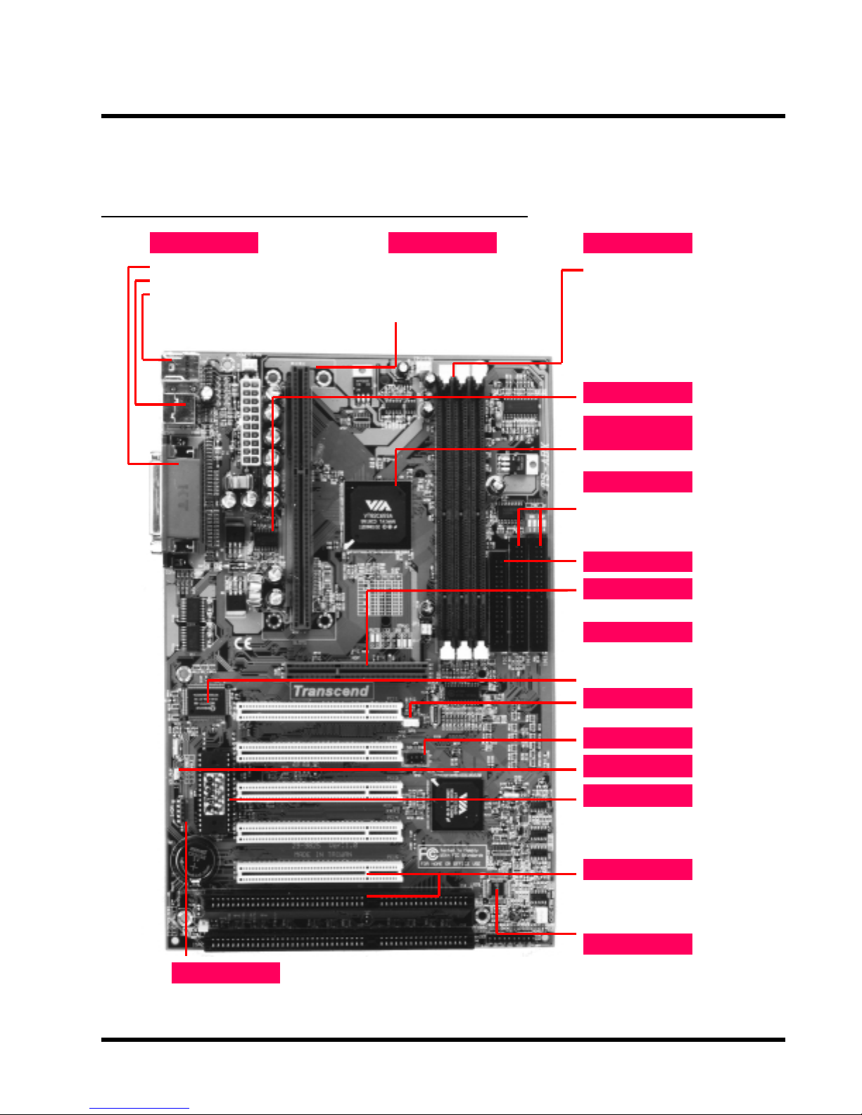
2.1 Transcend’s TS-AVD1 Motherboard
I/O Port Slot 1
2 x COM Ports & 1 x Parallel Port
·
2 x USB Ports
·
PS/2 KB Port & PS/2 Mouse Port
·
Pentium
·
CPU 233~450MHz
Celeron 266~533MHz
·
Pentium
·
®
II MMX
®
III 450~933+MHz
Memory
3 x 168-pin DIMM Sockets
·
Up to 1.5GB SDRAM
·
Switching Reg.
Via Apollo
Pro 133 Chipset
Support 66/100/133MHz FSB
·
PCI IDE Ports
Bus Master
·
PIO Mode 3/4
·
DMA Mode 2
·
Ultra DMA 33/66
·
FDC Port
AGP Connector
1X/2X AGP
·
Super I/O
16550 Fast UART
·
Support EPP&ECP Printers
·
Support IR transmission
·
WOL Header
Wake on LAN Header
·
SB-Linkc Header
IrDA Header
KB Wake-up
Flash EEPROM
®
Award
·
·
·
·
·
( one PCI/ISA shared)
BIOS
PnP, DMI
ACPI compliant
Expansion Slots
5 x PCI Slots
2 x ISA Slots
Health Monitor
Volta
e
·
Temperature
·
Fan Speed
·
6
y
y
y
HARDW ARE INST ALLA TION
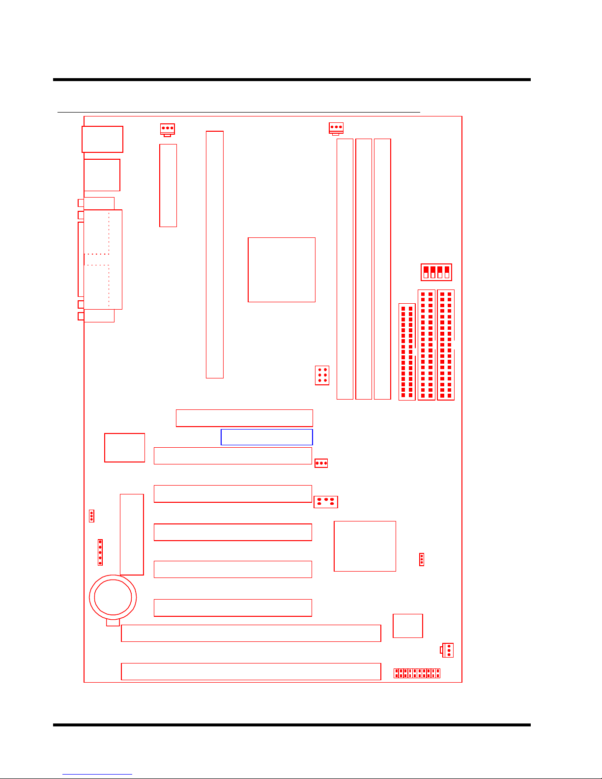
2.2 Layout of Transcend TS-AVD1 Motherboard
KB MOUSE
PS/2
T:Mouse
board
B:Ke
USB
USB
T:Port 1
B:Port 2
COMB
Printer
Parallel Port
COMA
POWER-FAN
Connector
ATX Power
Slot 1
CPU-FAN
CPU Freq.-
DIP Switch
VIA
693/693A
chipset
Ratio
SW1
Multi-I/O
Ke
Controller
JP5
KB-AWK
IrDA
Li Batter
&
board
(BIOS)
2Mbit Flash
AGP
Transcend
PCI Slot1 (PCI1)
PCI Slot2 (PCI2)
PCI Slot3 (PCI3)
PCI Slot4 (PCI4)
PCI Slot5 (PCI5)
ISA Slot1 (ISA1)
66/100/133MHz
WOL
596A/596B
DIMM1 (64/72bit 168pin SDRAM Module)
JP1
Wake-on-LAN
SB_Link
VIA
DIMM3 (64/72bit 168pin SDRAM Module)
DIMM2 (64/72bit 168pin SDRAM Module)
FDC
IDE2
JP4
CMOS-CLR
IDE1
Chipset
Hardware
Monitor
CASE-FAN
*T:Top
**B:Bottom
ISA Slot2 (ISA2)
Panel Connector
HARDW ARE INSTALLA TION
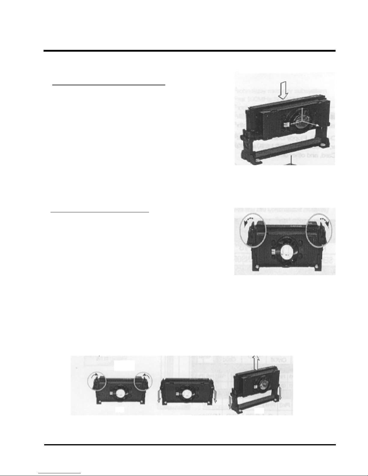
2.3 CPU(Central Processing Unit) Installation
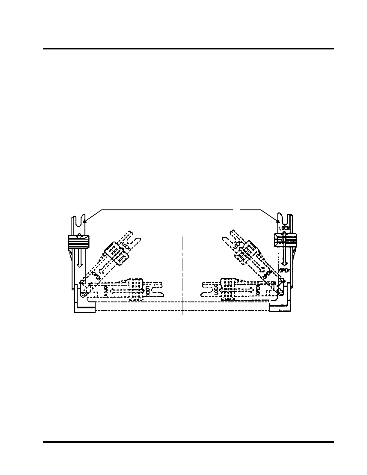
1. The Universal Retention Module (URM) should already be attched to your motherboard
when you unpack. It consists of two separate “Ears” to support the CPU. Before installing
the CPU, the ears must each be pulled upward 90 degree until they click into place when
upright, as in Diagram 1.
7
UNIVERSAL RETENTION MODULE
LOCK
OPEN
EAR
Diagram 1: Universal Retention Module (URM)
8 HARDWARE INSTALLATION
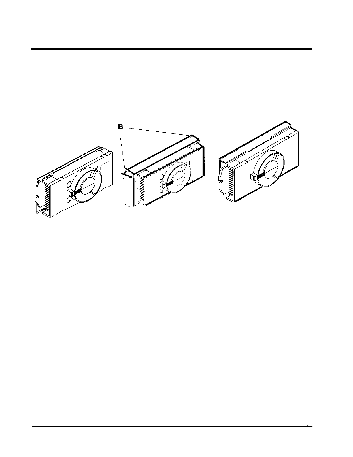
Intel Celeron Intel Pentium II Intel Pentium III
Processor Processor Processor
(S.E.P.P) (S.E.C.C) (S.E.C.C.2)
Diagram 2: The Intel Processor Type
2. There are three types of Intel Processor compatible with your motherboard’s URM. The
Intel Celeron™ Processor (Single Edge Processor Package or SEPP), the Intel Pentium
II Processor (Single Edge Context Cartridge or SECC) and the Intel Pentium ® III Processor
(also SECC). Please refer to Diagram 2. If your URM is not compatible with your
motherboard, please contact your motherboard retailer . See Diagram 2
3. T o install the CPU, carefully slide it into the URM. If you have a Pentium II CPU, you will need
to press in the Processor Latches to install it.
4. When the URM is installed on the PC Board, move the slider to the lock position to lock the
CPU. T o remove the CPU, push the Slider down to the Open position to unlock it.
®
HARDWARE INSTALLATION 9
• Installing the Intel Processor
Step 1: Install the Processor into Slot 1
Slide the processor into the URM assembly and insert it
into Slot 1, while making sure that the heat sink assembly
is facing towards the chipset, as shown in the figure.
Press down firmly on the CPU until it is fully seated in
the Slot 1 connector.
IMPORTANT: The Slot 1 connector is directionally
keyed and the processor will not go in unless it is
properly oriented. DO NOT apply excessive force
when installing the CPU.
Step 2: Lock the CPU in the URM
Lock the processor into the URM by pushing the top-right
and top-left latches to the outward position as shown in
the illustration.
• Removing the Processor
Step 1: Unlock the CPU by pushing the top-right and
top-left latches inward.
Step 2: Push both slides on the URM right and left
branches downward.
Step 3: Remove the processor by pulling it upward
while holding the two slides in the down
position.
A B C
A B C
10 HARDW ARE INSTALLATION
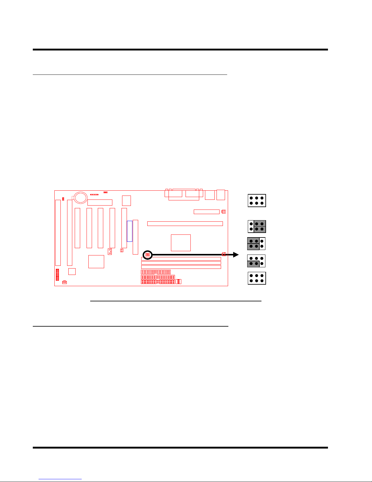
2.4 66/100/133MHz System Configuration
Jumper 1 (JP1) allows you to set the FSB (Front Side Bus) to 66, 100 or 133MHz configuration.
When you set the FSB to 66MHz, you can select a system bus frequency from 66MHz to 95MHz
through “CPU Host/PCI clock” in “Chipset Features Setup” (Please refer to page 31). When you
set the FSB to 100MHz, you can select a system bus frequency from 100MHz to 124MHz
through “CPU Host/PCI clock” in “Chipset Features Setup” (Please refer to page 31). When you
set the FSB to 133MHz, you can select a system bus frequency from 124MHz to 150MHz
through ”CPU Host/PCI clock” in “Chipset Features Setup” (Please refer to page 31).
NOTE: If you are not familar with this feature, we recommend you set this jumper to
“AUTO”.
Transcend
JP1
66/100/133MHz
1
AUTO
66MHz
100MHz
133MHz
66/100/133MHz FSB Configuration Jumper
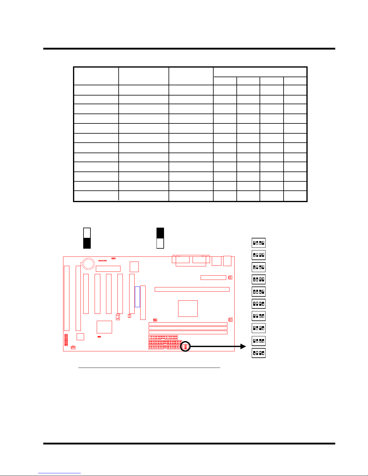
2.5 CPU Internal Frequency Ratio Setting
Switch 1 (SW1) is for adjusting the CPU’s internal frequency ratio. The frequency ratio settings
are shown in the table shown overleaf. The internal frequency can be calculated by the following
formula:
CPU internal frequency = frequency ratio x system bus frequency *
* System bus frequency is set in “CPU Host/PCI Clock” of “Chipset Features Setup” in BIOS
SETUP MENU (Please refer to page 31 ).
NOTE: Because Intel has locked the frequency ratio for new CPUs, setting SW1 to
adjust the frequency ratio is useless. However , it is effective for old version CPUs.
HARDW ARE INSTALLA TION
11
CPU Internal
Frequency
233/350/466MHz
266/400/533MHz
300/450/600MHz
333/500/666MHz
366/550/733MHz
400/600/800MHz
433/650/866MHz
466/700/933MHz
500/750MHz
533/800MHz
JP1
66/100/133MHz
66/100/133MHz
66/100/133MHz
66/100/133MHz
66/100/133MHz
66/100/133MHz
66/100/133MHz
66/100/133MHz
66/100MHz
66/100MHz
Freq.-Ratio
x 3.5
x 4.0
x 4.5
x 5.0
x 5.5
x 6.0
x 6.5
x 7.0
x 7.5
x 8.0
1
O
X
X
X
X
O
O
O
O
X
: ON(O) : OFF(X)
Transcend
CPU Freq.-Ratio DIP Switch Setting
SW1
2
X
O
O
X
X
O
O
X
X
O
SW1
ON DIP
1 2 3 4
ON DIP
1 2 3 4
ON DIP
1 2 3 4
ON DIP
1 2 3 4
ON DIP
1 2 3 4
ON DIP
1 2 3 4
ON DIP
1 2 3 4
ON DIP
1 2 3 4
ON DIP
1 2 3 4
ON DIP
1 2 3 4
3
X
O
X
O
X
O
X
O
X
O
Ratio
x 3.5
x 4.0
x 4.5
x 5.0
x 5.5
x 6.0
x 6.5
x 7.0
x 7.5
x 8.0
4
O
O
O
O
O
X
X
X
X
X
12 HARDWARE INSTALLATION
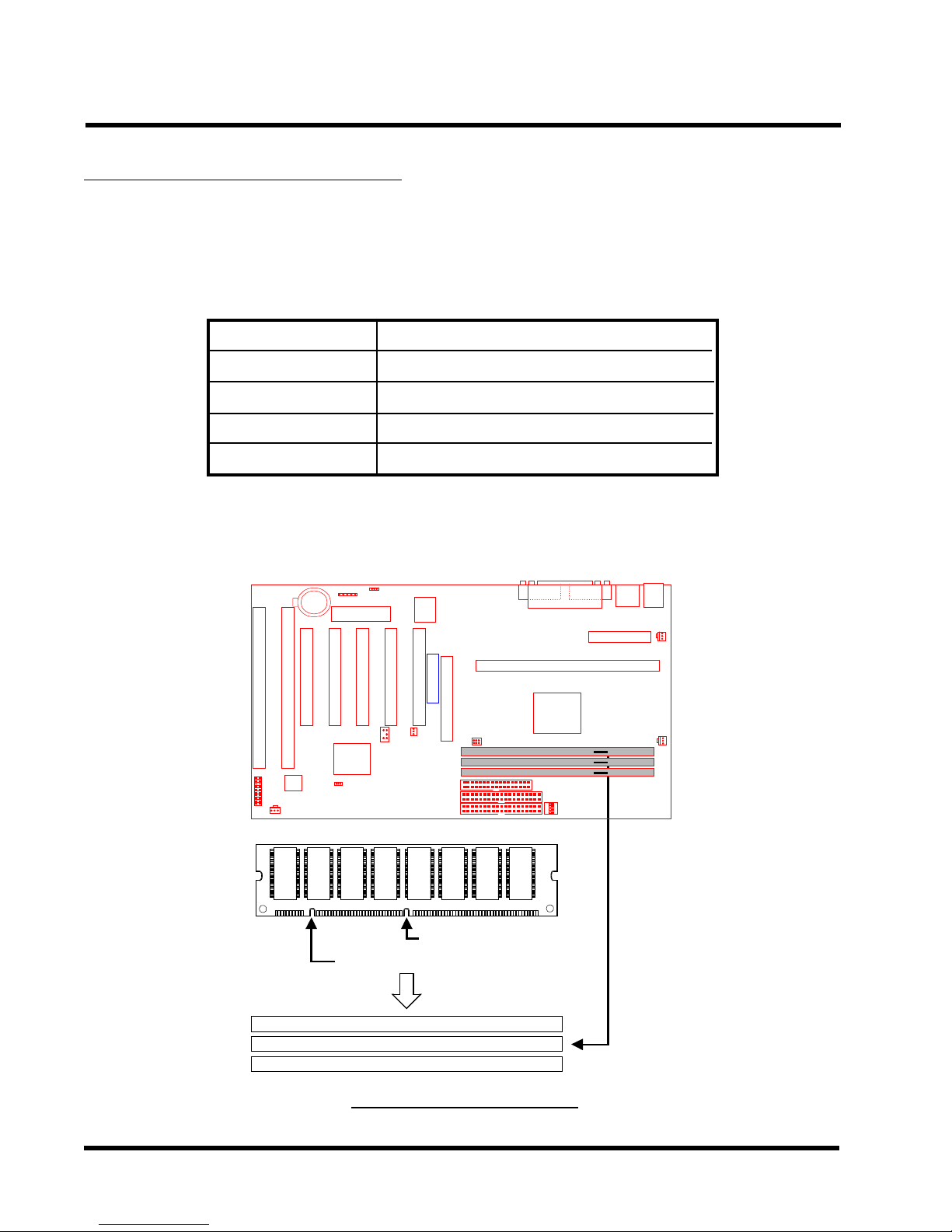
2.6 Memory Configuration
This motherboard must be installed with DIMM (Dual Inline Memory Module). The DIMMs must
be 3.3 Volt synchronous DRAM modules. The VIA Apollo Pro 133 chipset supports PC100,
PC133, Virtual Channel Memory (VCM) and EDO RAM. It also supports ECC (Error Checking
and Correcting) module. Y ou can install memory in any combination as follows:
DIMM Location
DIMM1
DIMM2
DIMM3
T otal Memory
SDRAM 8,16, 32, 64,128, 256MB
SDRAM 8,16, 32, 64,128, 256MB
SDRAM 8,16, 32, 64,128, 256MB
768MB (max.)
168-pin DIMM
NOTE: Different types of DRAM modules should not be installed on a motherboard at
the same time.
Transcend
168Pin SDRAM Module (DIMM1)
168Pin SDRAM Module (DIMM2)
168Pin SDRAM Module (DIMM3)
3.3V Position
Unbuffered Position
168Pin DIMM Sockets
 Loading...