

Transcend TS-ALR4 User Manual

TS-ALR4
USER’S MANUAL
AMD Duron/Athlon Socket A CPU

TS-ALR4 Motherboard
Supporting AMD Duron / Athlon Socket A CPU
200 MHz Front Side Bus Frequency
AGP 4X
ALi 1647/1535D+ Chipset
Welcome !!
Congratulations on your purchase of this great value motherboard, with its range of special
features and innovative onboard functions, built around the advanced architecture of the new et.
More details to follow later in this manual.
Our Website
Please come and visit us at our website on http://www.transcendusa.com/. Y ou’ll find plenty of
interesting information about this and many other quality Transcend products.
Your User’s Manual
This User’s Manual is designed to help end users and system manufacturers to set up and
install the motherboard. All of the information within has been carefully checked for accuracy .
However, Transcend Information, Inc. (hereafter referred to as “Transcend”) carries no
responsibility or liability for any errors or inaccuracies which this manual may contain. This
includes references to products and software. In addition, the information and specifications
are subject to change without prior notice.
Disclaimer
Transcend provides this manual “as is” without any warranty of any kind, either expressed or
implied, including - but not limited to - the implied warranties, conditions of merchantability or
fitness for a particular purpose. Transcend, its management, employees, distributors and
agents are in no way liable for any indirect special, incidental or consequential damages,
including loss of profits, loss of business and the like. This is even if Transcend has been
advised of the possibility of such damages arising from any defect or error in this manual or
product.
Trademarks
All brands, product names and trademarks mentioned in this document are the property of
their respective owners or companies and are used solely for identification or explanation. It
is Transcend policy to respect all product rights.
Copyright
This manual may not, in whole or in part, be photocopied, reproduced, transcribed, translated
or transmitted, in whatever form or language, without the written consent of the manufacturer,
except for copies retained by the purchaser for personal archiving purposes.
Manual Version: 1.1
Release Date: February, 2001
Copyright © 2000 Transcend Information, Inc.

ezBIOS—Motherboard Shield and Upgrade
Utility
ezBIOS—One Click is All it Takes!
Transcend is proud to inform you that your new motherboard comes with ezBIOS from
Transcend. This BIOS updating program developed by Transcend will make BIOS updating easy, and enhance the security and stability of systems built with your Transcend
motherboard.
ezBIOS Features:
• Anti-Virus BIOS Protection – Transcend’s motherboards come with a new hard-
ware monitoring function that can prevent any unauthorized BIOS updating caused
by viruses. Only ezBIOS, the BIOS updating program developed by Transcend,
can update a Transcend motherboard.
• BIOS Updating Confidence – Beyond preventing viruses, ezBIOS allows BIOS
updating with confidence. In the past, any failure or incorrect operation during
BIOS updating could crash the whole system. Normally the user wouldn’t have
the capability to retrieve and reestablish the system, they could only return the
computer to the supplier for costly , time-consuming repairs. With the enhanced
security of ezBIOS, Transcend’s motherboards can completely avoid these problems. No matter what happens during BIOS updating, the user’s system can still
boot from the floppy drive, allowing the updating command to be executed again.
• One-Click, On-Line BIOS Updating – For users of Windows 95/98, ezBIOS allows
you to use Transcend’s innovative on-line updating technology. Just one click can
detect the BIOS version of your system, download the latest version, and execute
all the updating commands automatically from the Internet. Restarting the computer completes the BIOS updating. This feature should be very handy for users
who need to update BIOS repeatedly, especially MIS staff. The on-line updating
program is included on the drivers CD-ROM included in the box with your
motherboard. Following the step-by-step instructions, you can easily update or
backup your BIOS. (If you have a different OS, see Chapter 4 BIOS Upgrade for
your BIOS updating procedure.)
• Linear Overclocking – ezBIOS also provides a linear overclocking function. Users
can fine-tune the Front Side Bus (FSB) by increasing or reducing it by as little as
1.0MHz to find the optimum FSB setting for the system. (For details see “Frequency/Voltage Control” in Chapter 3.) Should the FSB be set too high, the system can be returned to the default setting by pressing the “INS” key.

T able of Contents
CHAPTER 1 INTRODUCTION 1
1.1 Essential Handling Precautions .........................................................................1
1.2 Checklist:Hardware Require for Setup..............................................................2
1.3 Package Contents ............................................................................................2
1.4 Specifications and Features..............................................................................3
CHAPTER 2 HARDW ARE INSTALLATION 5
2.1 T ranscend TS-ALR4 Motherboard ....................................................................5
2.2 Layout of T ranscend TS-ALR4 Motherboard ....................................................6
2.3 CPU Installation ................................................................................................7
2.4 100/133MHz System Configuration...................................................................9
2.5 CPU Internal Frequency Ratio Setting ........................................................ 10
2.6 Memory Configuration.....................................................................................11
2.7 Primary/Secondary IDE Connectors...............................................................12
2.8 Floppy Disk Drive Connector ..........................................................................13
2.9 Fan Power Connectors...................................................................................13
2.10 Wake-on-LAN Connector................................................................................14
2.11 Wake-on-Modem Connector...........................................................................1 4
2.12 IrDA-Compliant Infrared Module Connector ....................................................15
2.13 Panel Connectors ...........................................................................................15
2.14 Power Connector............................................................................................1 7
2.15 External Rear Panel I/O Ports ........................................................................17
2.16 Using Jumper JP4 to clear CMOS..................................................................19
2.17 Internal Audio Connector ................................................................................20
2.18 Internal USB Port Connector...........................................................................21

CHAPTER 3 BIOS SETUP 22
3.1 BIOS Setup....................................................................................................... 22
3.2 The Main Menu ................................................................................................. 22
3.3 Standard CMOS Features ................................................................................ 25
3.4 Advanced BIOS Features ................................................................................. 2 7
3.5 Advanced Chipset Features ..............................................................................31
3.6 Integrated Peripherals.......................................................................................33
3.7 Power Management Setup................................................................................37
3.8 PnP/PCI Configuration Setup ............................................................................42
3.9 PC Health Status............................................................................................... 44
3.10 Frequency/V oltage Control................................................................................45
3.11 Load Fail-Safe Defaults ....................................................................................46
3.12 Load Optimized Defaults...................................................................................4 6
3.13 Set Password ..................................................................................................47
3.14 Save & Exit Setup .............................................................................................49
3.15 Exit Without Saving ...........................................................................................49
CHAPTER 4 BIOS UPGRADE 50
4.1 How to Check Your BIOS File Name and Version ............................................. 50
4.2 How to Download the Correct BIOS File from the Web .................................... 50
4.3 How to Update Your Motherboard BIOS...........................................................51

1 INTRODUCTION
CHAPTER 1 INTRODUCTION
1.1 Essential Handling Precautions
IMPORT ANT :Read this page before unpacking your motherboard!
• Power Supply
Caution! Always ensure that the computer is disconnected from the power supply when working
on the motherboard and its components.
• Static Electricity
Static electricity may cause damage to the delicate integrated circuit chips on your motherboard.
Before handling the motherboard outside of its protective packaging, ensure that there is no
static electric charge in your body . To avoid this risk, please observe these simple precautions
while handling the motherboard and other computer components:
1. If possible, wear an anti-static wrist strap. This fits around your wrist and is connected to
a natural earth ground.
2. Touch a grounded or anti-static surface, or a metal fixture such as a pipe or the chassis of
your system, before touching the motherboard.
3. When you have removed the motherboard from its anti-static packaging, try to hold it only
by the edges, without touching any components.
4. Avoid contacting the components on add-on cards, motherboards, and modules with the
golden fingers (gold-colored connectors) which plug into the expansion slots.
5. It is safest to handle system components only by their mounting brackets.
6. Keep components which are not connected to the system in the anti-static packaging
whenever possible.
These precautions help to reduce the risk of static build-up and ensure any static discharge is
harmless to your equipment.
••
• Battery Replacement
••
The battery which holds the system settings on your motherboard should not require replacement for at least five years, and probably much longer. In picture 2.2, it is located near the
bottom right hand corner.

INTRODUCTION 2
Please replace your battery only with the same type, or a similar type recommended by the
manufacturer. If the battery is replaced incorrectly, there is a risk of a short circuit or explosion.
Used batteries should disposed of according to the manufacturer’s instructions.
••
• Electric Screwdrivers
••
To reduce the risk of damage to the motherboard due to excessive torque, avoid setting
electric screwdrivers above 7.5 kg/cm.
1.2 Checklist: Hardware Required for Setup
It is advisable to have all of these items of hardware available before you unpack your
motherboard from its anti-static packaging and start building your system.
- Computer case and chassis with appropriate power supply . (300W recommended)
- Monitor.
- Socket A Central Processing Unit (CPU).
- DDR DIMM memory module.
- PS/2 or USB Keyboard.
- PS/2 or USB Mouse.
- Hard Disk Drive.
- Floppy Disk Drive.
- CD-ROM Drive.
- (Optional) External Peripherals: printer, speakers, plotter, modem.
- (Optional) Internal Peripherals: modem, LAN cards.
1.3 Package Contents
This motherboard package should contain the following items. Please check them as soon as
you unpack. If you find any damaged or missing items, please contact your retailer.
- TS-ALR4 motherboard
- 1 x CD-ROM
- 1 x FDD cable
- 1 x Ultra DMA/66/100 cable
- User’s Manual
- 1 x External USB connector (optional)

3 INTRODUCTION
1.4 Specifications and Features
• •
• CPU
• •
- Supports AMD Duron / Athlon 550MHz~1.2G+Hz Socket A CPU
• •
• Chipset
• •
- ALi 1647/1535D+
• •
• DRAM Memory
• •
- Supports DDR DRAM
- 3 x 184-pin DDR DIMM module sockets on board
- Up to 3GB memory size
- 4/16/64/128/256/512/1024 MB DDR
- Supports ECC
• •
• Extenision Slot
• •
- 1 x AGP 2X/4X slot
- 6 x Master/Slave PCI slots (PCI 2.2 compliant)
• •
• I/O Port
• •
- Supports PIO Mode 3,4 ATAPI devices and Ultra DMA33/66/100
- Supports 2 high speed UART 16550 COM ports
- Supports SPP/EPP/ECP LPT port
- Supports 1.44/2.88 MB floppy drive
- Supports PS/2 Mouse and PS/2 Keyboard
- Supports IrDA port
- Supports 4 USB ports (2 by Cable)
- Supports Line-out,Line-in and MIC-in jack.
- Supports Game/MIDI port

INTRODUCTION 4
•
Award BIOS
- Supports Plug-and-Play , PC99
- Supports ACPI, APM, DMI and Green Feature
- Easy BIOS Recovery
- Supports Transcend ez BIOS
•
Wake Up Features
- Supports Wake-on-LAN function
- Remote Ring Wake Up
- Time W ake Up
•
PCB Dimensions
- ATX form factor, 4-layer PCB, 21.3cm x 30.5cm (8.4 inch x 12 inch)
•
Switching Voltage Regulator
- VRM 9.0 compliant
•
Other Features
- Year 2000 compliant
- Anti-Virus Boot up
- System voltage monitors for CPU Vcore, VDDQ, +3.3V, +5V, +12V, -12V, -5V, VBAT,
5VSB
(
)
(
)
5 HARDWARE INSTALLATION
CHAPTER 2 HARDWARE INST ALLATION
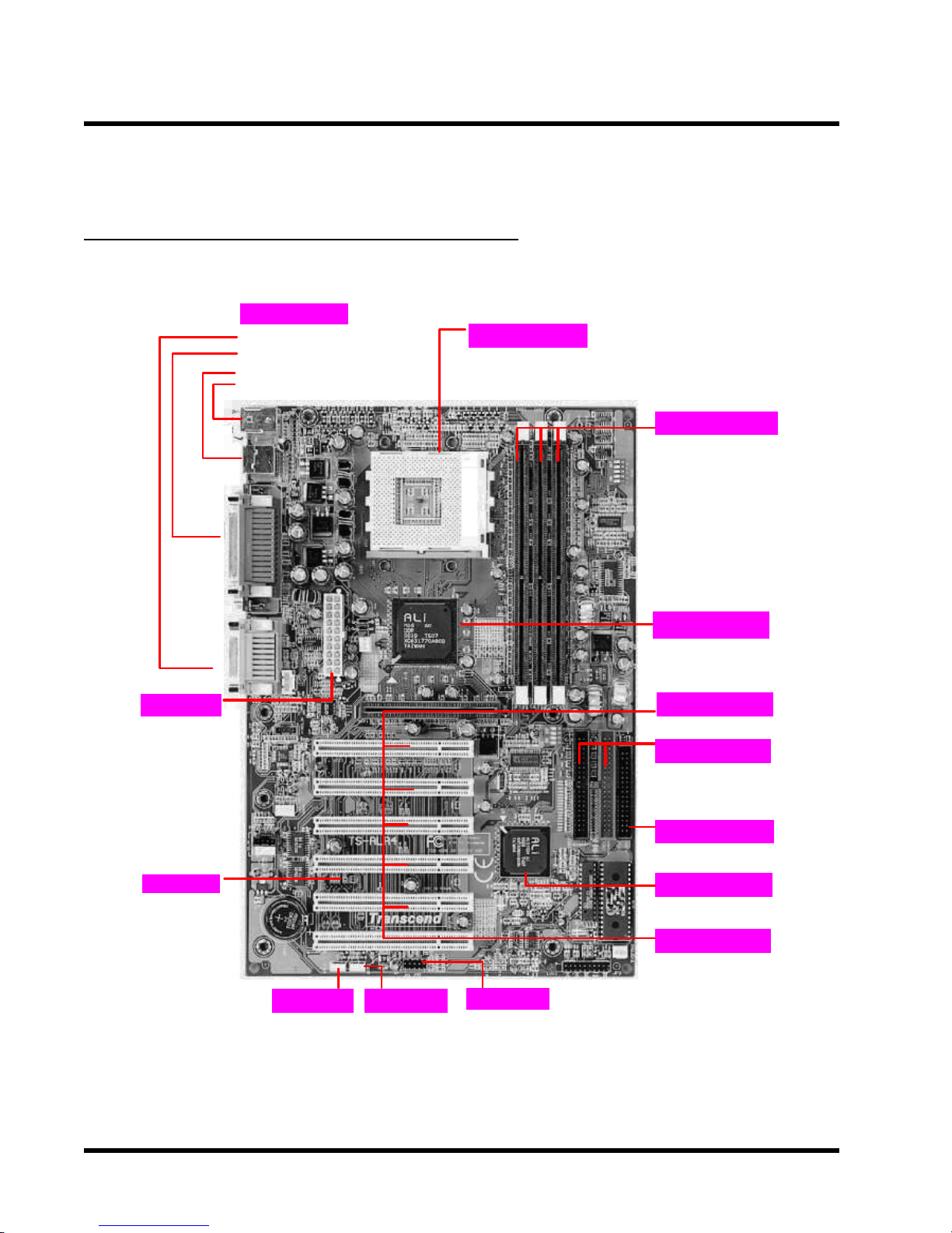
2.1 Transcend TS-ALR4 Motherboard
I/O Port
General MIDI Port & Audio Jack
·
Line-In, Line-Out, MIC-In
·
2 x COM Ports & 1 x Parallel Port
2 x USB Ports
·
·
PS/2 KB Port & PS/2 Mouse Port
CPU
AMD Duron / Athlon Socket A
·
CPU
FSB 200/266MHz
3 x 184 -pin DDR Module
·
·
Support up to 3GBytes
KX133 Chipset
Memory
Power
Connector
IrDA
WOL Header
Wake-on-LAN
·
WOM Header
·
Wake-on-Modem
USB3/4
ALi 1647
North Bridge
·
AGP Connector
·
·
Supports AGP1X/2X/4X
PCI IDE Connector
·
·
Bus Master
PIO Mode 3/4
·
·
DMA Mode 2
·
·
Ultra DMA 33/66/100
·
FDD Connector
ALi1535D+
South Bridge
·
·
Expansion Slots
6 x PCI Slots
··
1 x AGP Slot
··
g
g
HARDWARE INSTALLATION 6
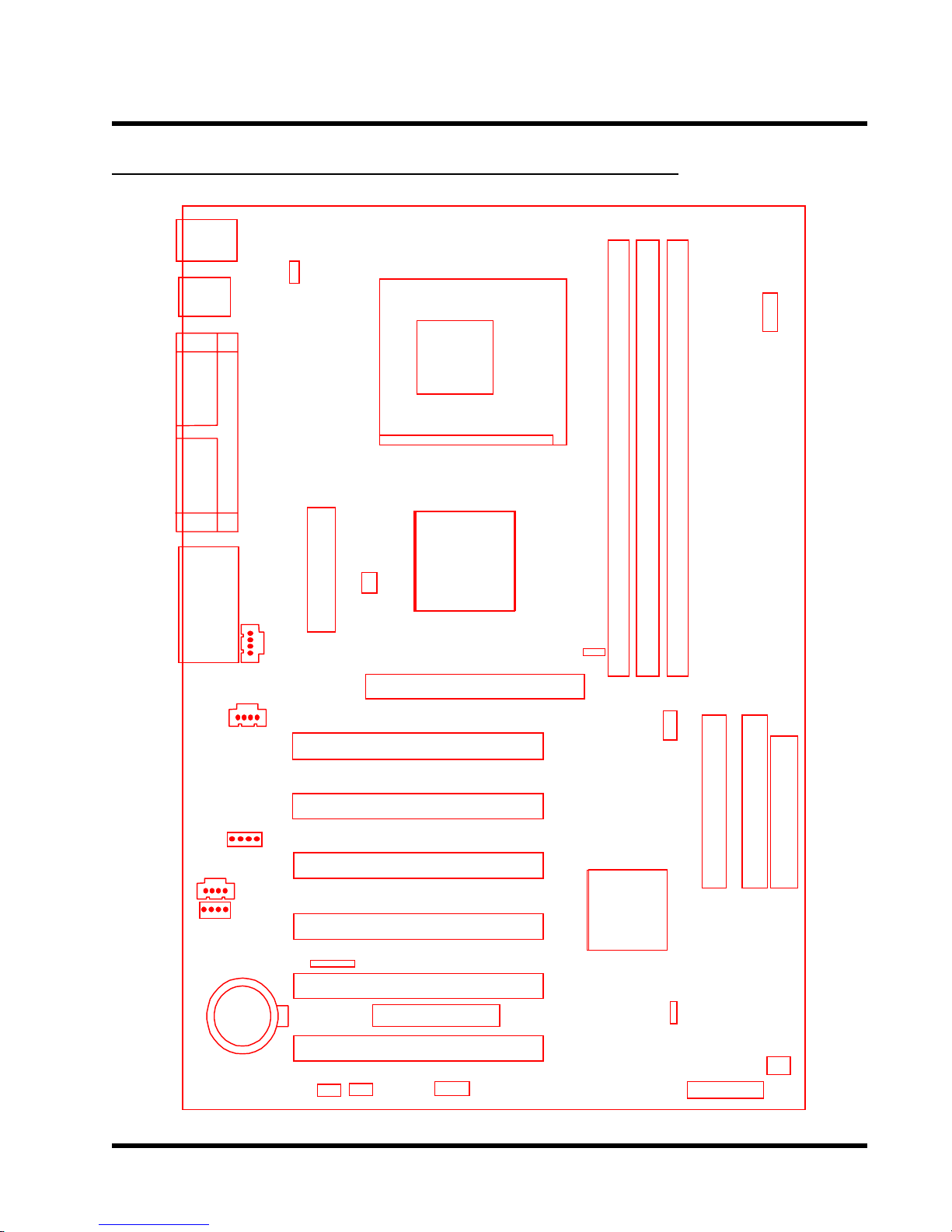
2.2 Layout of Transcends TS-ALR4 Motherboard
KB MOUSE
USB1/2
COMA
COMB
Audio
PRN
VIDEO
JP1
CPU FAN
Power Connector
AUX
PCI Slot1 (PCI1)
Socket462
Nouth
Brid
e
ALi1647
AGP
DIMM1( 184pin DDR Module)
JP5
DIMM3( 184pin DDR Module)
DIMM2( 184pin DDR Module)
SW1
SW2
IDE1IDE2
FDC
MODEM
CD1
CD2
Battery
PCI Slot2 (PCI2)
PCI Slot3 (PCI3)
PCI Slot4 (PCI4)
IrDA
PCI Slot5 (PCI5)
Transcend
PCI Slot6 (PCI6)
WOL WOM
USB3/4
South
Brid
e
ALi1535D+
JP4
Panel Connector
SYS
FAN

7 HARDWARE INSTALLATION
2.3 CPU Installation
So far you have familiarized yourself with the handling precautions, checked you have all of
the necessary hardware for building your system, inspected the motherboard package contents
and looked at the layout of the motherboard. This chapter will take you step by step through
the process of installing the different hardware devices onto it.
Caution!
1. Remember to always make sure the system power is off before installing or removing
any devices.
2. Don’t forget the static electricity precautions.
3. Be careful ! Inserting hardware onto your motherboard incorrectly can damage it.
The motherboard has a ZIF Socket A which houses the CPU. A fan is necessary for the CPU
to prevent overheating. If there is no fan on it, please purchase one before you turn on your
system.
Caution!
This kind of CPU will generate tremendous heat while opearting,make sure install the
CPU fan and enough heat-dissipation grease before power up the computer.Never run
the processor without the heatsink properly and firmly attached.
PERMANENT DAMAGE WILL RESUL T!
Please follow the steps below to install the CPU:
Step 1:
To install the CPU, first turn off your system and remove its cover. Locate the ZIF socket and
open it by first pulling the lever sideways away from the socket then upwards to a 90-degree
right angle. Insert the CPU in the correct direction, smear the heat dissipation grease over the
CPU die,then put a CPU fan to cover the face of the CPU. With the added weight of the CPU fan,
no force is required to insert the CPU. Once completely inserted, close the socket’s lever while
holding down the CPU.
HARDWARE INSTALLATION 8
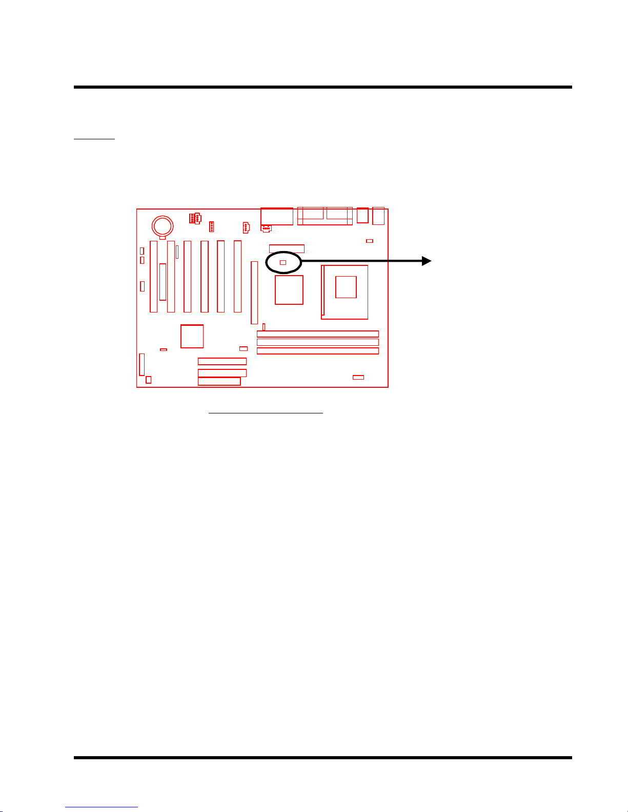
Step 2:
Connect the CPU’s fan cable to the CPU-FAN connector indicated on the diagram below.
Ensure that the cable is connected correctly! It will be obvious which way it fits.
Transcend
CPU-FAN
CPU Installation
9 HARDWARE INSTALLATION
2.4 100/133 MHz System Configuration
The SW1 allows you to set the FSB (Front Side Bus) for 100, or 133 MHz Configuration.
SW1
4
3
OX
X
X
X
X
Transcend
CPU
100
133
O: ON
X: OFF
12
O
O
100/133 MHz FSB Configuration Jumper
HARDWARE INSTALLATION 10
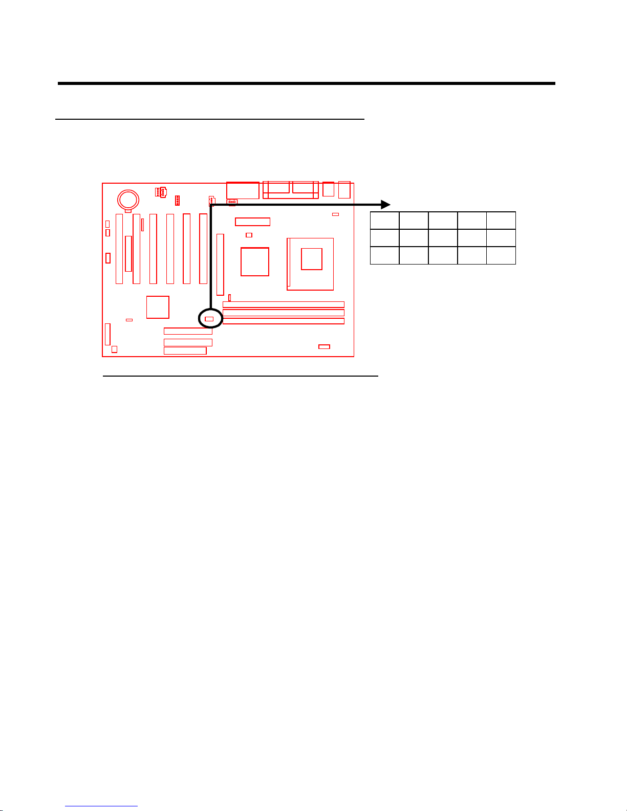
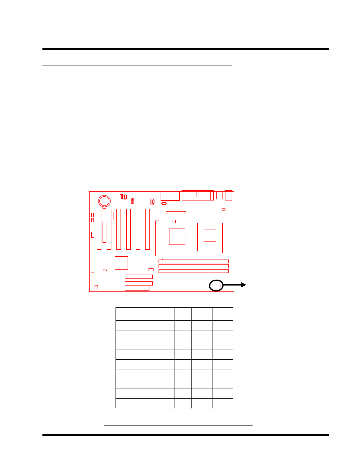
2.5 CPU Internal Frequency Ratio Setting
The switch 2 (SW2) is designated for adjusting the CPU internal frequency ratio. The frequency
ratio is defined in the table below. The internal frequency can be calculated by the following
formula:
CPU internal frequency = frequency ratio x FSB frequency *
* System bus frequency is set in “CPU Host/PCI Clock” of “Frequency ” in BIOS SETUP MENU
(Please refer to page 45 ).
NOTE: Because AMD has locked the frequency ratio for new CPUs, setting SW2 to
adjust the frequency ratio is useless. However, it is effective for older version
CPUs.
Transcend
O: ON
X: OFF
SW2
Default
5.0
5.5
6.0
6.5
7.0
7.5
8.0
8.5
SW2
123 4
O
XO
O
X
O
X
O
X
X
O
X
O
X
X
X
X
O
O
O
O
X
O
X
O
O
O
O
O
X
X
X
X
5
X
O
O
O
O
O
O
O
CPU Internal Frequency Ratio Setting
11 HARDW ARE INSTALLATION
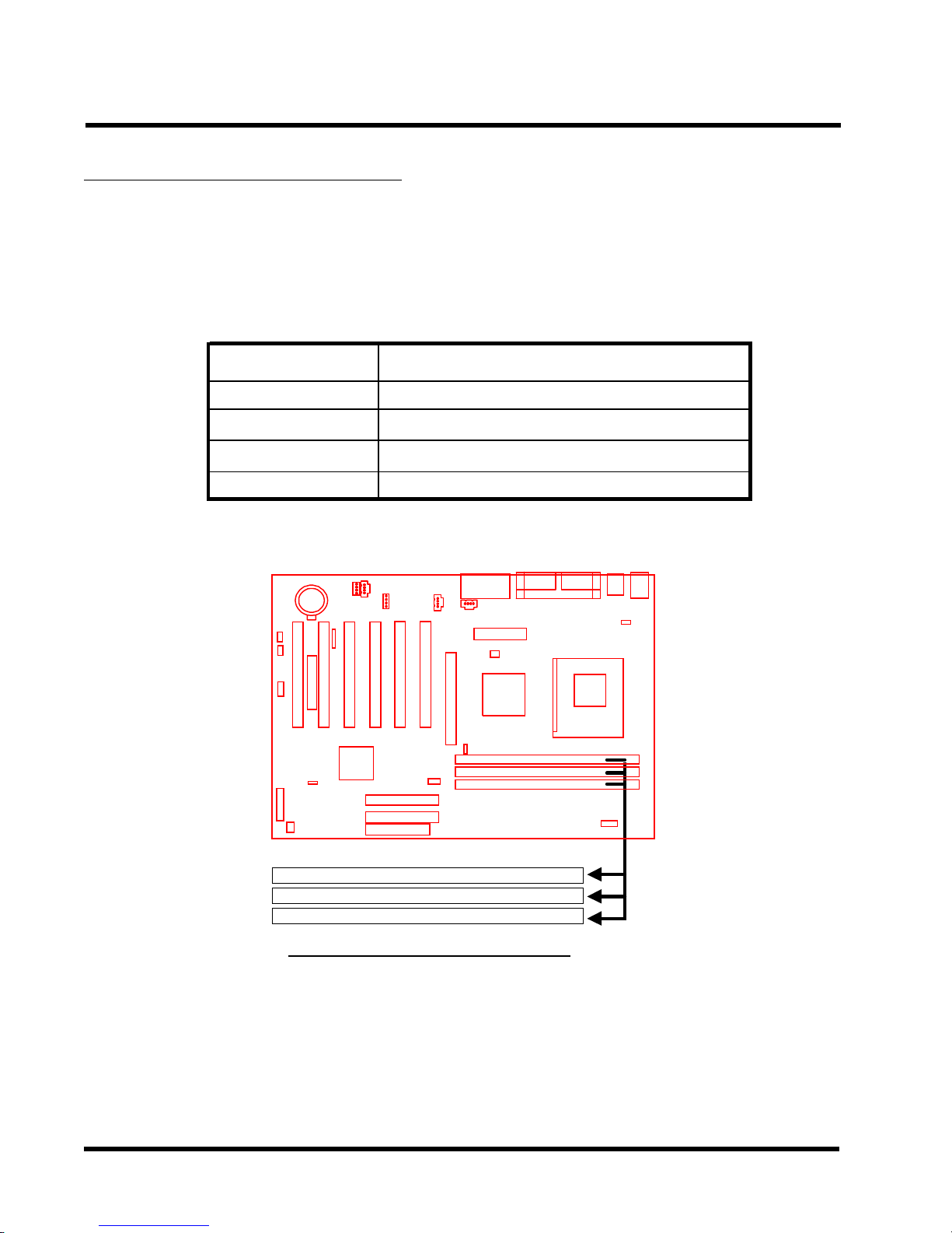
2.6 Memory Configuration
This motherboard must be installed with DIMMs (Dual Inline Memory Modules). The DIMMs
must be 2.5 Volt DDR DRAM modules. You can install memory in any combination as follows:
DIMM Location
DIMM1
DIMM2
DIMM3
Total Memory
Transcend
184-pin DIMM
DDR 4,16, 64,128, 256, 512,1024MBytes
DDR 4,16, 64,128, 256, 512,1024MBytes
DDR 4,16, 64,128, 256, 512,1024MBytes
3GBytes (max.)
184 Pin DDR DIMM Sockets
184 Pin DDR Module (DIMM1)
184 Pin DDR Module (DIMM2)
184 Pin DDR Module (DIMM3)

HARDWARE INSTALLATION 12
2.7 Primary / Secondary IDE Connectors (Two 40-pin IDE)
This mainboard supports two 40-pin IDE connectors marked as IDE1 (primary IDE channel)
and IDE2 (secondary IDE channel). Each channel supports two IDE devices, making a total of
four devices. Connect your Hard Disk (the main one if you are using more than one) to the
“Master” connector (at the end of the cable) and connect it to the IDE1 (see important note
below). If your HDD supports UltraDMA/66/100, you must use an 80-wire cable, otherwise the
HDD won’t be able to reach this speed.
If you intend to operate two IDE devices from the same channel, one device must be set to
“Master” mode, the other to “Slave” mode. A Hard Disk, CD ROM or other IDE device can
have either s e tting, depending on device’s jumper. Please refer to the device’s manual for
more information.
NOTE: The connectors must be attached to the IDE channels the right way round.
Make sure that the red stripe on one edge of the ribbon cable (this may be faint
and could also be a dotted line) is the nearest to PIN1 (on the left as the
motherboard is shown in the picture below).
Note: Orient the red
stripe to Pin1
Transcend
Secondary IDE Connector
Primary IDE Connector
PIN1
IDE2
IDE1
PIN1
IDE Connectors
 Loading...