

Page 1
T
T
T
S
S
S
6
6
6
0
0
0
G
G
G
S
S
S
S
S
S
D
D
D
2
2
2
5
5
5
D
D
D
-
-
-
M
M
M
T
T
T
S
S
S
1
1
1
2
2
2
0
0
0
G
G
G
S
S
S
S
S
S
D
D
D
2
2
2
5
5
5
D
D
D
-
-
-
M
M
M
2.5” Solid State Drive
Transcend Information Inc.
Preliminary V1.0
1
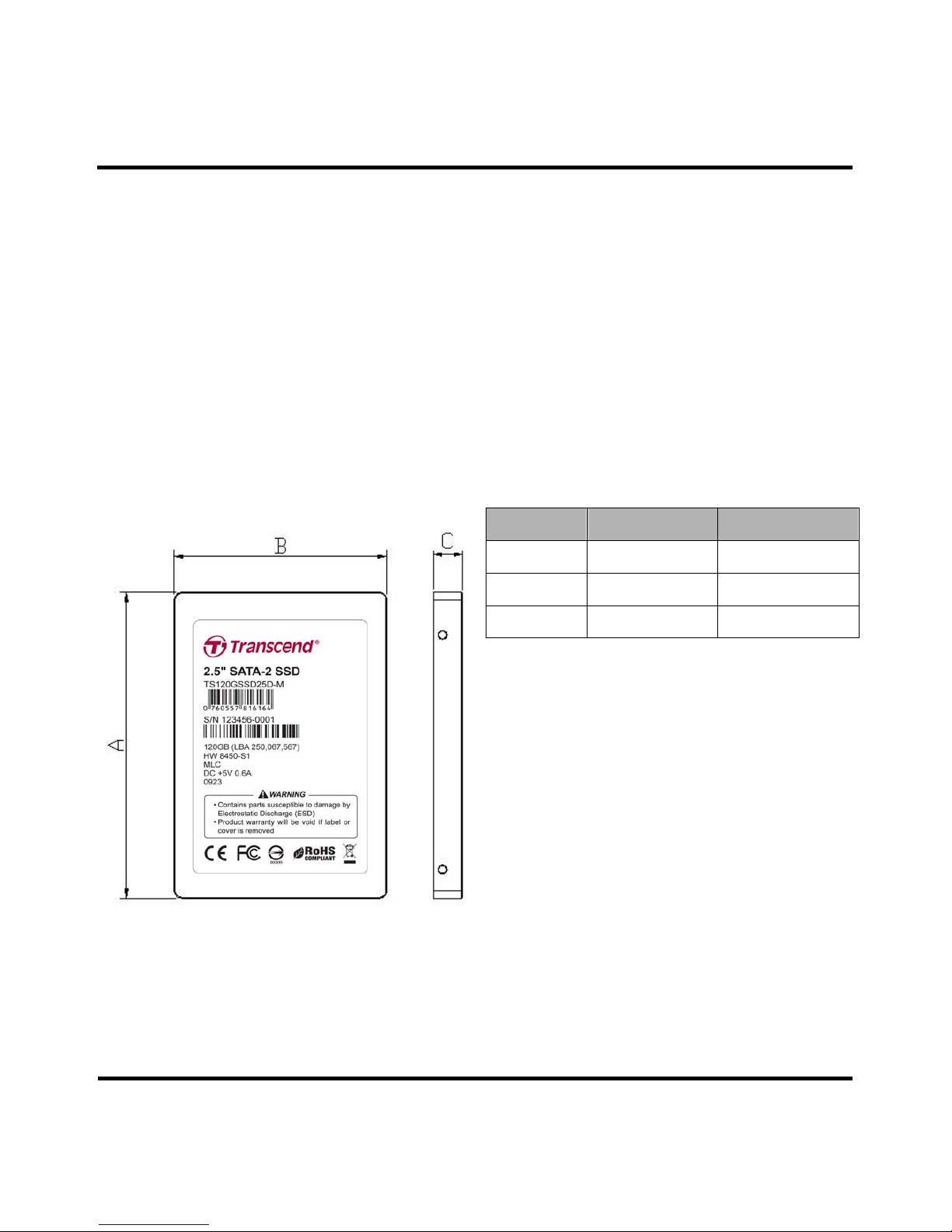
Description
Transcend 2.5” SATA II solid state drive is a hu ge
capacity, high speed, and low power consumption
without moving parts which design for take the place
of traditional hard disk drive. It provides fast read and
write performance for high end system such as
server and storage system. Build in advance ECC
and global wear-leveling provide a durable solution is
perfect replacement storage device for Server
systems, Storage systems, PCs, Laptops and
gaming systems.
Placement
Features
• Fully SATA II 3.0Gbps compatible
• Non-volatile Flash Memory for outstanding data
retention
• Built-in DRAM cache buffer
• Built-in ECC (Error Correction Code) functionality and
wear-leveling algorithm ensures highly relia ble of da ta
transfer
• Lower Power Consumption
• Shock resistance
Dimensions
Side Millimeters Inches
A
100.00 ± 0.40 3.937 ± 0.016
B
69.85 ± 0.20 2.750 ± 0.008
C
9.50 ± 0.20 0.374 ± 0.008
Page 2
T
T
T
S
S
S
6
6
6
0
0
0
G
G
G
S
S
S
S
S
S
D
D
D
2
2
2
5
5
5
D
D
D
-
-
-
M
M
M
T
T
T
S
S
S
1
1
1
2
2
2
0
0
0
G
G
G
S
S
S
S
S
S
D
D
D
2
2
2
5
5
5
D
D
D
-
-
-
M
M
M
2.5” Solid State Drive
Transcend Information Inc.
Preliminary V1.0
2
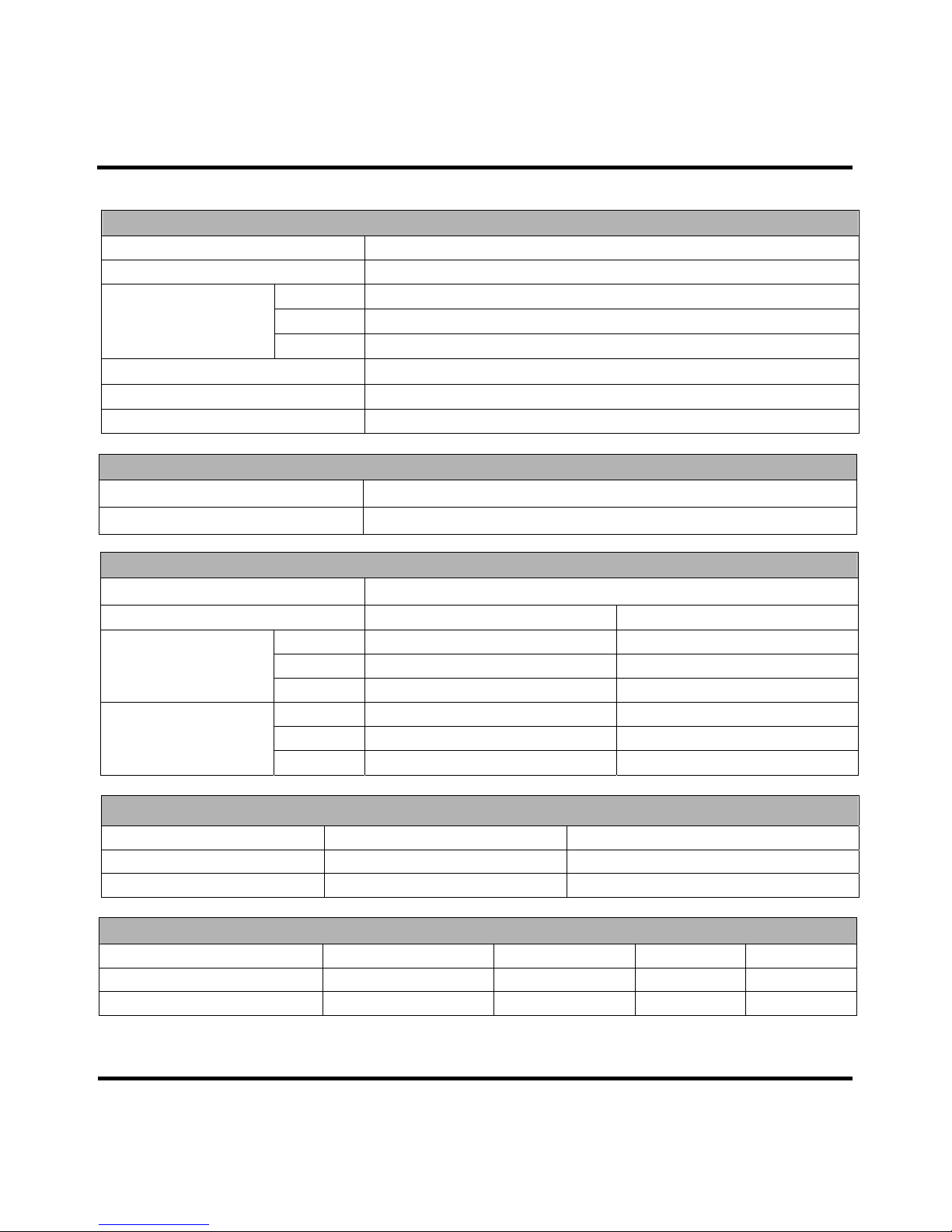
Specifications
Physical Specification
Form Factor
2.5-inch HDD
Storage Capacities
60GB and 120GB
Length
100.00 ± 0.40
Width
69.85 ± 0.20
Dimensions (mm)
Height
9.50 ± 0.20
Input Voltage
5V ± 5%
Weight
91g ± 2g
Connector
SATA 7+15 pins combo connector
Environmental Specifications
Operating Temperature
0
℃ to 70 ℃
Storage Temperature
- 40
℃ to 85 ℃
Performance
Model P/N
Sequential Read
(Max.)
Sequential Write
(Max.)
TS60GSSD25D-M 210 MB/s 150 MB/s
TS120GSSD25D-M 230 MB/s 180 MB/s
Actual Capacity
Model P/N User Max. LBA Cylinder Head Sector
TS60GSSD25D-M 125,045,424 7,783 255 63
TS120GSSD25D-M 250,067,567 15,565 255 63
Power Requirements
Input Voltage
5V ± 5%
@25℃
Mode Max. (mA) Max. (W)
Write
(peak)
395.6 1.98
Read
(peak)
176.7 0.88
Power Consumption
(60GB)
Idle
(peak)
88.3 0.44
Write
(peak)
534.9 2.67
Read
(peak)
196.9 0.98
Power Consumption
(120GB)
Idle
(peak)
88.3 0.44
Page 3
T
T
T
S
S
S
6
6
6
0
0
0
G
G
G
S
S
S
S
S
S
D
D
D
2
2
2
5
5
5
D
D
D
-
-
-
M
M
M
T
T
T
S
S
S
1
1
1
2
2
2
0
0
0
G
G
G
S
S
S
S
S
S
D
D
D
2
2
2
5
5
5
D
D
D
-
-
-
M
M
M
2.5” Solid State Drive
Transcend Information Inc.
Preliminary V1.0
3
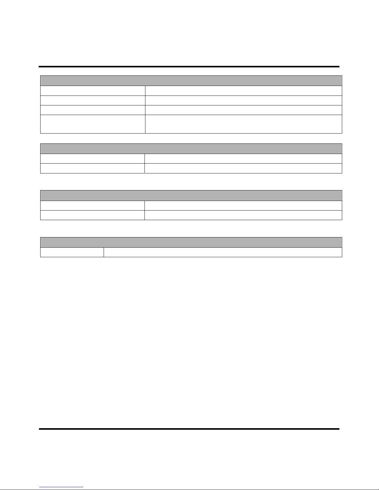
Reliability
Data Reliability
Supports BCH ECC 8 ,12 or 16bits/sector
Data Retention
10 years
MTBF
1.5M hours
Endurance
60GB: 75.7 years @ 20GB write/day
120GB: 151.4 years @ 20GB write/day
Vibration
Operating
5.0G, 15 – 800Hz
Non-Operating
5.0G, 15 – 800Hz
* Note: Reference to the IEC 60068-2-6 Testing procedures; Operating-Sine wave, 5-800Hz/1 oct., 1.5mm, 3g, 0.5
hr./axis, total 1.5 hrs.
Shock
Operating
1500G, 0.5ms
Non-Operating
1500G, 0.5ms
* Note: Reference to the IE C 60068-2-27 Testing procedures; Operating-Half-sine wave, 1500g, 0.5ms, 3 times/d ir., total
18 times.
Regulations
Compliance
CE, FCC and BSMI
Page 4
T
T
T
S
S
S
6
6
6
0
0
0
G
G
G
S
S
S
S
S
S
D
D
D
2
2
2
5
5
5
D
D
D
-
-
-
M
M
M
T
T
T
S
S
S
1
1
1
2
2
2
0
0
0
G
G
G
S
S
S
S
S
S
D
D
D
2
2
2
5
5
5
D
D
D
-
-
-
M
M
M
2.5” Solid State Drive
Transcend Information Inc.
Preliminary V1.0
4
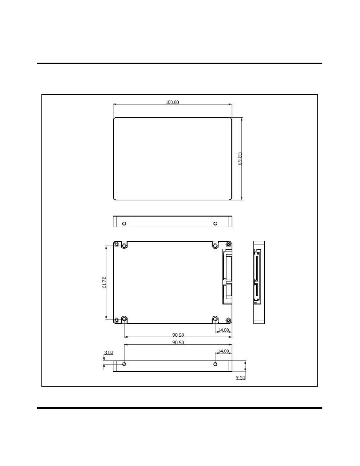
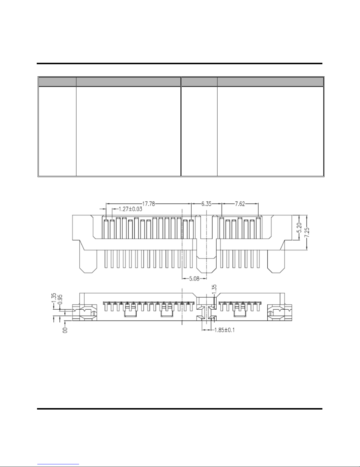
Package Dimensions
Below figure illustrates the Transcend 2.5” SATA Solid State Drive. All dimensions are in mm.
Page 5
T
T
T
S
S
S
6
6
6
0
0
0
G
G
G
S
S
S
S
S
S
D
D
D
2
2
2
5
5
5
D
D
D
-
-
-
M
M
M
T
T
T
S
S
S
1
1
1
2
2
2
0
0
0
G
G
G
S
S
S
S
S
S
D
D
D
2
2
2
5
5
5
D
D
D
-
-
-
M
M
M
2.5” Solid State Drive
Transcend Information Inc.
Preliminary V1.0
5
Pin Assignments
Pin No. Pin Name Pin No. Pin Name
01 GND 02 A+
03 A- 04 GND
05 B- 06 B+
07 GND 08 NC
09 NC 10 NC
11 GND 12 GND
13 GND 14 5V
15 5V 16 5V
17 GND 18 DAS/DSS
19 GND 20 NC
21 NC 22 NC
Pin Layout
1
7 8
22
Page 6
T
T
T
S
S
S
6
6
6
0
0
0
G
G
G
S
S
S
S
S
S
D
D
D
2
2
2
5
5
5
D
D
D
-
-
-
M
M
M
T
T
T
S
S
S
1
1
1
2
2
2
0
0
0
G
G
G
S
S
S
S
S
S
D
D
D
2
2
2
5
5
5
D
D
D
-
-
-
M
M
M
2.5” Solid State Drive
Transcend Information Inc.
Preliminary V1.0
6
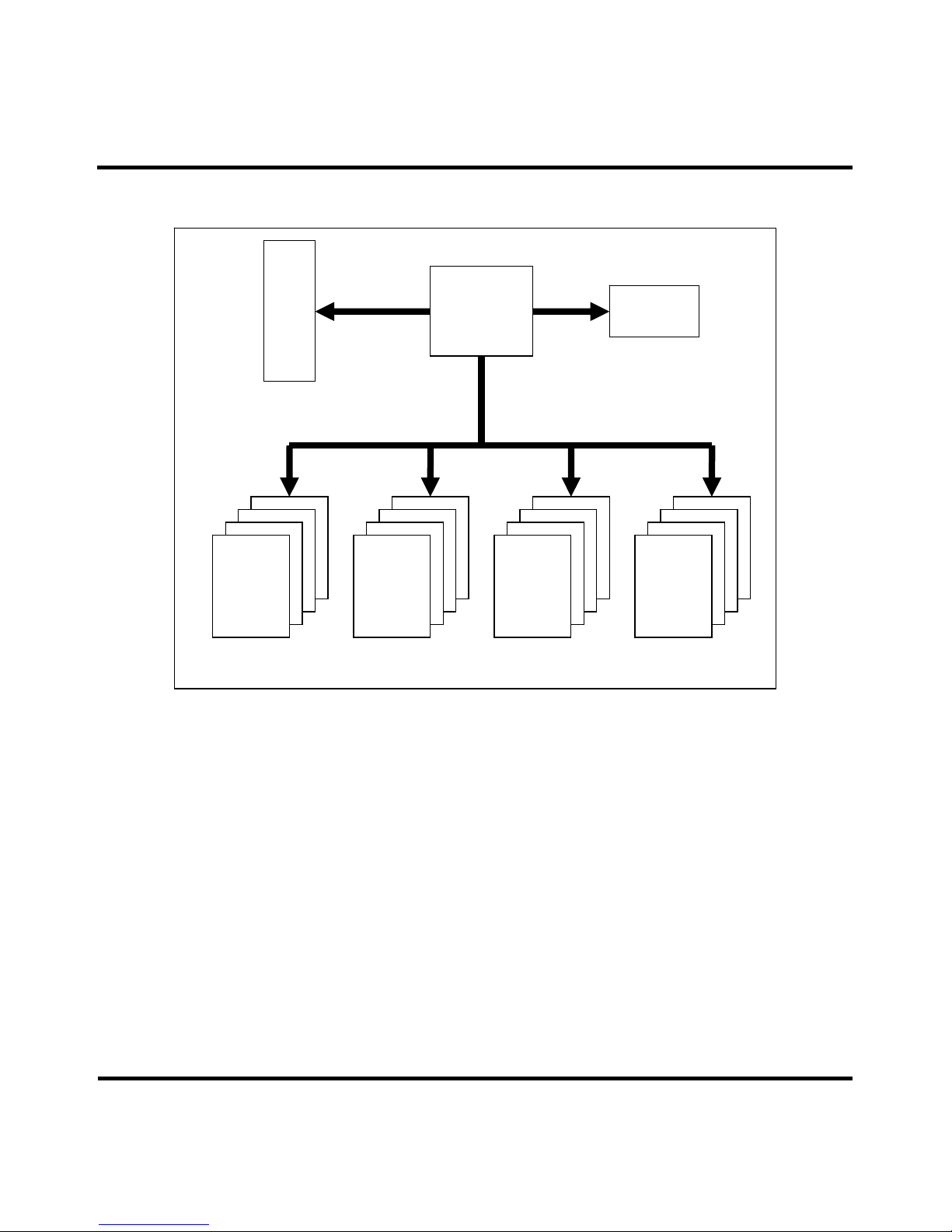
Block Diagram
Flash
Flash
Flash
Flash
Flash
Flash
Flash
Flash
Flash
Flash
Flash
Flash
Flash
Flash
Flash
Flash
S
ATA II 3.
0Gb/s
32bits
16bits 16bits 16bits 16bits
SATA
SSD
Controller
SATA Connector
DRAM
Page 7

T
T
T
S
S
S
6
6
6
0
0
0
G
G
G
S
S
S
S
S
S
D
D
D
2
2
2
5
5
5
D
D
D
-
-
-
M
M
M
T
T
T
S
S
S
1
1
1
2
2
2
0
0
0
G
G
G
S
S
S
S
S
S
D
D
D
2
2
2
5
5
5
D
D
D
-
-
-
M
M
M
2.5” Solid State Drive
Transcend Information Inc.
Preliminary V1.0
7
Reliability
Wear-Leveling algorithm
The controller supports static/dynamic wear leveling. When the host writes data, the controller will find and use the block
with the lowest erase count among the free blocks. This is known as dynamic wear leveling. When the free blocks' erase
count is higher than the data blocks', it will activate the static wear leveling, replacing the not so frequently used user
blocks with the high erase count free blocks.
ECC algorithm
The controller use Reed Solomon code or BCH code option
Reed Solomon: 6Bytes/sector for 128Bytes spare and 12Bytes/sector for 218Bytes spare
BCH: 8 or 12 bits/sector for 128Bytes spare and 16bits/sector for 218Bytes spare size
Bad-block management
When the flash encounters ECC failed, program fail or erase fail, the controller will mar k the block as bad block to
prevent the used of this block and caused data lost later on.
Page 8

T
T
T
S
S
S
6
6
6
0
0
0
G
G
G
S
S
S
S
S
S
D
D
D
2
2
2
5
5
5
D
D
D
-
-
-
M
M
M
T
T
T
S
S
S
1
1
1
2
2
2
0
0
0
G
G
G
S
S
S
S
S
S
D
D
D
2
2
2
5
5
5
D
D
D
-
-
-
M
M
M
2.5” Solid State Drive
Transcend Information Inc.
Preliminary V1.0
8
Supported ATA Command Lists
Page 9

T
T
T
S
S
S
6
6
6
0
0
0
G
G
G
S
S
S
S
S
S
D
D
D
2
2
2
5
5
5
D
D
D
-
-
-
M
M
M
T
T
T
S
S
S
1
1
1
2
2
2
0
0
0
G
G
G
S
S
S
S
S
S
D
D
D
2
2
2
5
5
5
D
D
D
-
-
-
M
M
M
2.5” Solid State Drive
Transcend Information Inc.
Preliminary V1.0
9
SMART
SMART subcommand sets
In order to select a subcommand the host must write the subcommand code to the device's Features Register b efore
issuing the SMART Function Set command. The subcommands are listed below.
SMART Read Data (subcommand D0h)
This subcommand returns the device's Attribute Values to the host. The Attribute Values consist of 512bytes.
Device Attribute Data Structure
Individual Attribute Data Structure
Page 10

T
T
T
S
S
S
6
6
6
0
0
0
G
G
G
S
S
S
S
S
S
D
D
D
2
2
2
5
5
5
D
D
D
-
-
-
M
M
M
T
T
T
S
S
S
1
1
1
2
2
2
0
0
0
G
G
G
S
S
S
S
S
S
D
D
D
2
2
2
5
5
5
D
D
D
-
-
-
M
M
M
2.5” Solid State Drive
Transcend Information Inc.
Preliminary V1.0
10
Attribute ID Numbers
* indicates that the corresponding Attribute Values is fixed value for compatibility.
SMART Save Attribute Values (subcommand D3h)
This subcommand causes the device to immediatel y save any updated Attribute Values to the device's Attribute D ata
sector regardless of the state of the Attribute Autosave feature.
SMART Execute Off-line Immediately (subcommand D4h)
This subcommand causes the device to start the off-line process for the reque sted mode and op eration. The LBA Low
register shall be set to specify the operation to be executed.
SMART Read Log Sector (subcommand D5h)
This command returns the specified log sec tor co ntent to the hos t. LBA Low and Sector Count re gisters s hall be se t to
specify the log sector and sector number to be written.
SMART Log Directory
SMART summary error log sector
Page 11

T
T
T
S
S
S
6
6
6
0
0
0
G
G
G
S
S
S
S
S
S
D
D
D
2
2
2
5
5
5
D
D
D
-
-
-
M
M
M
T
T
T
S
S
S
1
1
1
2
2
2
0
0
0
G
G
G
S
S
S
S
S
S
D
D
D
2
2
2
5
5
5
D
D
D
-
-
-
M
M
M
2.5” Solid State Drive
Transcend Information Inc.
Preliminary V1.0
11
Error log data structure
Command data structure
Page 12

T
T
T
S
S
S
6
6
6
0
0
0
G
G
G
S
S
S
S
S
S
D
D
D
2
2
2
5
5
5
D
D
D
-
-
-
M
M
M
T
T
T
S
S
S
1
1
1
2
2
2
0
0
0
G
G
G
S
S
S
S
S
S
D
D
D
2
2
2
5
5
5
D
D
D
-
-
-
M
M
M
2.5” Solid State Drive
Transcend Information Inc.
Preliminary V1.0
12
Error data structure
State field values
Self-test log structure
N is 0 through 20.
The data structure contains the descriptor of the Self-test that the device has performed. Each descriptor is 24 bytes long
and the self-test data structure is c apable to contain up to 21 des criptors. After 21 descriptor s has been recorded, th e
oldest descriptor will be overwritten with the new descriptor. The self-test log pointer points to the most recent descriptor.
When there is no descriptor, the value is 0. When there are descriptor(s), the value is 1 through 21.
Page 13

T
T
T
S
S
S
6
6
6
0
0
0
G
G
G
S
S
S
S
S
S
D
D
D
2
2
2
5
5
5
D
D
D
-
-
-
M
M
M
T
T
T
S
S
S
1
1
1
2
2
2
0
0
0
G
G
G
S
S
S
S
S
S
D
D
D
2
2
2
5
5
5
D
D
D
-
-
-
M
M
M
2.5” Solid State Drive
Transcend Information Inc.
Preliminary V1.0
13
Selective self-test log st ructure
SMART Write Log Sector (subcommand D6h)
This command writes 512 bytes of data to th e spec ified log s ec tor. LBA Lo w an d Sec tor Co unt re gisters shall be set to
specify the log address and sector number to be written.
SMART Enable Operations (subcommand D8h)
This subcommand enables access to all SMART capabilities. Prior to receipt of a SMART Enable Operations
subcommand, Attribute Values are neither monitored nor saved by the device . The s tate of SMART— either en ab led or
disabled—will be preserved by the device across power cycles. Once enabled, the receipt of subsequent SMART
Enable Operations subcommands will not affect any of the Attribute Values.
SMART Disable Operations (subcommand D9h)
This subcommand disables all SMART capabilities. After receipt of this subcommand the device disables all SMART
operations. Non self-preserved Attribute Values will no longe r be monitored. The state of SMART—either e nabled or
disabled—is preserved by the device acro ss pow er cyc les. Note that this subcomm and doe s not p reclude the de vice's
power mode attribute auto saving.
After receipt of the SMART Disable Operation s subcommand from the host, all other SMART subcommands exc ept
SMART Enable Operations are disabled and will be aborted by the device returning the error code as specified in
“SMART Error Codes”.
Any Attribute Values accumulated and saved to volatile memory prior to receipt of the SMART Disable Operations
command will be preserved in the device's Attribute Data Sectors. If the device is re-enabled, these Attribute Values will
be updated, as needed, upon receipt of a SMART Read Attribute Values or a SMART Save Attribute Values command.
Page 14

T
T
T
S
S
S
6
6
6
0
0
0
G
G
G
S
S
S
S
S
S
D
D
D
2
2
2
5
5
5
D
D
D
-
-
-
M
M
M
T
T
T
S
S
S
1
1
1
2
2
2
0
0
0
G
G
G
S
S
S
S
S
S
D
D
D
2
2
2
5
5
5
D
D
D
-
-
-
M
M
M
2.5” Solid State Drive
Transcend Information Inc.
Preliminary V1.0
14
SMART Return Status (subcommand DAh)
This subcommand is used to communicate the reliability status of the device to the host's request. Upon receipt of the
SMART Return Status subcommand the device saves any updated Attribute Values to the reserved sector, and
compares the updated Attribute Values to the Attribute Thresholds.
SMART Enable/Disable Automatic Off-line (subcommand DBh)
This subcommand enables and disables the optional feature that caus e the device to perform the set of off-line data
collection activities that automatically collect attribute data in an off-line mode and then save this data to the device's
nonvolatile memory. This subcommand may either cause the device to automatic ally initiate or resu me p erfo rmanc e of
its off-line data collection activities or cause the automatic off-line data collection feature to be disabled. This
subcommand also enables and disables the off-line read scanning feature that ca use the device to perform the entir e
read scanning with defect reallocation as the part of the off-line data collection activities. The Sector Count register shall
be set to specify the feature to be enabled or disabled:
Sector Count Feature Description
00h Disable Automatic Off-line
F8h Enable Automatic Off-line
A value of zero written by the host into the device's Sector Count regis ter be fore iss uing this subc ommand s hall cause
the automatic off-line data collection feature to be disabled. Disabling this feature does not preclude the device from
saving attribute values to nonvolatile memory during some other no rma l ope ra tion such as during a power-on, during a
power-off sequence, or during an error recovery sequence. A value of F8h written by the host into the device's Sector
Count register before issuing this subcommand sh all cause th e autom atic Off-lin e data collect ion feature to be enabled.
Any other non-zero value written by the host into this register before issuing this subcommand is vendor specific and will
not change the current Automatic Off-Line Data Collection and Off-line Read Scanning status. However, the device may
respond with the error code specified in “SMART Error Codes”.
Security
Default setting
The Flash SSD is shipped with master password set to 20h value (ASCII blanks) and the loc k function disabled. The
system manufacturer/dealer may set a new master password by using the SECURITY SET PASSWORD command,
without enabling the lock function.
Initial setting of the user password
When a user password is set, the drive automatically enters lock mode by the next powered-on.
SECURITY mode operation from power-on
In locked mode, the Flash SSD rejects media access commands until a SECURITY UNLOCK command is successfully
completed.
Password lost
If the user password is lost and High level security is set, the drive does not allow the user to access any data. However,
Page 15

T
T
T
S
S
S
6
6
6
0
0
0
G
G
G
S
S
S
S
S
S
D
D
D
2
2
2
5
5
5
D
D
D
-
-
-
M
M
M
T
T
T
S
S
S
1
1
1
2
2
2
0
0
0
G
G
G
S
S
S
S
S
S
D
D
D
2
2
2
5
5
5
D
D
D
-
-
-
M
M
M
2.5” Solid State Drive
Transcend Information Inc.
Preliminary V1.0
15
the drive can be unlocked using the master password.
If the user password is lost and Maximum security level is set, it is impossible to access data. However, the drive can be
unlocked using the ERASE UNIT command with the master password. The drive will erase all user data and unlock the
drive.
SATA Optional Features
Power Segment Pin P11
Pin P11 of the power segment of the device connector may be used by the device to provide the host with an activity
indication. The activity indication provided by pin P11 is primarily for use in backplane applications.
Asynchronous Signal Recovery
Phy may support asynchronous signal recovery for those applications where the usage model of device insertion into a
receptacle (power applied at time of insertion) does not apply.
When signal is lost, both the host and the device may attempt to recover the signal. A host or device shall determine loss
of signal as represented by a transition from PHYRDY to PHYRDYn, which is associated with entry into s tates LSI:
NoCommErr or LS2:NoComm within the Link layer. Note that negation of PHYRDY does not always constitute a loss of
signal. Recovery of the signa l is associated with exit from state LS2:NoComm. If the device atte mpts to recover the
signal before the host by issuing a COMINIT, the device shall return its signature following completion of the OOB
sequence which included COMINIT. If a host supports synchronous signal recovery, when the host receives an
unsolicited COMINIT, the host shall issue a COMRESET to the device. An unsolicited COMINIT is a COMINIT that was
not in response to a preceding COMRESET, as defined by the host not being in the HP2:HR_AwaitCOMINIT state when
the COMINIT signal is first received.
When a COMRESET is sent to the device in response to an unsolicited COMINIT, t he host shall set the Status register to
7Fh and shall set all other Shadow Command Block Registers to FFh. When the COMINIT is received in response to the
COMRESET which is associated with entry into state HP2B:HR_ AwaitNoCOMINIT, the Shadow Status regis ter value
shall be updated to either FFh or 80h to reflect that a device is attached.
Page 16

T
T
T
S
S
S
6
6
6
0
0
0
G
G
G
S
S
S
S
S
S
D
D
D
2
2
2
5
5
5
D
D
D
-
-
-
M
M
M
T
T
T
S
S
S
1
1
1
2
2
2
0
0
0
G
G
G
S
S
S
S
S
S
D
D
D
2
2
2
5
5
5
D
D
D
-
-
-
M
M
M
2.5” Solid State Drive
Transcend Information Inc.
Preliminary V1.0
16
Identify Device Parameters
Word Contents Description
0 0C5Ah General information
1 3FFFh Number of logical cylinders
2 C837h Specific configuration
3 0010h Number of logical heads
4 – 5 0 Retired
6 003Fh Number of logical sectors per logical track
7 – 8 0 Reserved
9 0000h Retired
10 -19 XXXX Serial number(20 ASCII characters)
20 0000h Retired
21 4000h Buffer Memory Size
22 3000h Obsolete
23 - 26 XXXX Firmware revision (8 ASCII characters)
27- 46 XXXX Model number
47 8010h Number of sectors on multiple commands
48 0000h Reserved
49 2F00h Capabilities
50 4000h Capabilities
51 - 52 0200h PIO Mode support
53 0007h Reserved
54 3FFFh Number of current logical cylinders
55 0010h Number of current logical heads
56 003Fh Number of current logical sectors per track
57 FC10h
58 00FBh
Obsolete
59 0110h Multiple sector setting
60 XXXXh
61 XXXXh
Total number of user addressable sectors (LBA mode only)
62 0000h Obsolete
63 0007h Multi-word DMA transfer
64 0003h Flow control PIO transfer modes supported
65 0078h Minimum Multiword DMA transfer cycle time per word
66 0078h Manufacturer’s recommended Multiword DMA transfer cycle time per word
67 0078h Minimum PIO transfer cycle time without flow control
68 0078h Minimum PIO transfer cycle time with IORDY flow control
69 - 74 0 Reserved
75 001Fh Queue Depth
76 0706h Serial ATA capability
77 0000h Reserved
78 004Ch Serial ATA features supported
79 0048h Serial ATA features enabled
Page 17

T
T
T
S
S
S
6
6
6
0
0
0
G
G
G
S
S
S
S
S
S
D
D
D
2
2
2
5
5
5
D
D
D
-
-
-
M
M
M
T
T
T
S
S
S
1
1
1
2
2
2
0
0
0
G
G
G
S
S
S
S
S
S
D
D
D
2
2
2
5
5
5
D
D
D
-
-
-
M
M
M
2.5” Solid State Drive
Transcend Information Inc.
Preliminary V1.0
17
80 00E0h Major Version Number
81 0000h Minor Version Number
82 346Bh Command sets supported
83 7D21h Command sets supported
84 4022h Command set/feature supported extension
85 3469h Command set/feature enabled
86 3C01h Command set/feature enabled
87 4022h Command set/feature default
88 407Fh Ultra DMA transfer
89 0000h Time required for security erase unit completion
90 0000h Time required for Enhanced security erase completion
91 0000h Current advanced power management value
92 0000h Master Password Revision Code
93 0000h COMRESET result
94 0000h Automatic acoustic management value
95 0000h Stream minimum request size
96 - 99 0 Reserved
100 - 103 XXXX Maximum user LBA for 48bit address feature set
104-105 0 Reserved
106 0000h Physical sector size / logical sector size
107 0000h Reserved
108 - 111 XXXX Unique ID
112 - 116 0 Reserved
117 - 118 0 Words per logical sector
119 - 126 0 Reserved
127 0000h Removable media status notification feature set supported
128 XXXXh Security status
129 - 159 0 Undefined
160-254 0 Reserved
255 XXXXh Integrity word
Page 18

T
T
T
S
S
S
6
6
6
0
0
0
G
G
G
S
S
S
S
S
S
D
D
D
2
2
2
5
5
5
D
D
D
-
-
-
M
M
M
T
T
T
S
S
S
1
1
1
2
2
2
0
0
0
G
G
G
S
S
S
S
S
S
D
D
D
2
2
2
5
5
5
D
D
D
-
-
-
M
M
M
2.5” Solid State Drive
Transcend Information Inc.
Preliminary V1.0
18
Ordering Information
Capacity
60GB or 120GB
Solid State Drive
Transcend Product
-S = SLC
-M = MLC
Form Factor
25D = 2.5" SATA w/ DRAM
The above technical information is based on industry standard data and has been tested to be reliable. However,
Transcend makes no warranty, either expressed or implied, as to its accuracy and assumes no liability in connection with
the use of this product. Transcend reserves the right to make changes to the specifications at any time without prior notice.
USA
Los Angeles:
E-mail: sales@transcend u sa.com
Maryland:
E-mail: sales_md@transcendusa.com
www.transcendusa.com
CHINA
E-mail: sales@transcendc hina.com
www.transcendchina.com
GERMANY
E-mail: vertrieb@tran s cend.de
www.transcend.de
HONG KONG
E-mail: sales@transcend. com.hk
www.transcendchina.com
JAPAN
E-mail: sales@transcend. c o.jp
www.transcend.jp
THE NETHERLANDS
E-mail: sales@transcend . nl
www.transcend.nl
United Kingdom
E-mail: sales@transcend -uk.com
www.transcend-uk.com
TAIWAN
No.70, XingZhong Rd., NeiHu Dist., Taipei, Taiwan, R.O.C
TEL +886-2-2792-8000
Fax +886-2-2793-2222
E-mail: sales@transcend.com.tw
www.transcend.com.tw
KOREA
E-mail: sales@transcend . kr
www.transcend.co.kr
 Loading...