

Transact Campus VR4101X008 Installation Manual

Vending Reader VR4100
Installation Guide

This Class B digital apparatus complies with
Canadian ICES-003
Cet appareill numérique de la classes B est conform
à la norme NMB-003 du Canada
This device complies with Part 15 of the FCC Rules. Operation is subject to the following two conditions: (1) This
device may not cause harmful interference, and (2) this device must accept any interference received, including
interference that may cause undesired operation.
Part 15.21: Changes or modifications not expressly approved by the party responsible for compliance could void the user’s
authority to operate the equipment.
NOTE: The manufacturer is not responsible for any radio or TV interference caused by unauthorized modifications to this
equipment. Such modifications could void the user’s authority to operate the equipment.
This equipment complies with the FCC radiation exposure limits set forth for an uncontrolled environment. End users must
follow the specific operating instructions for satisfying RF exposure compliance. The antenna(s) used for this transmitter must
be installed to provide a separation distance of at least 20 cm from all persons and must not be co-located or operating in
conjunction with any other antenna or transmitter.

C ONTENTS
1VENDING READER VR4100 INSTALLATION GUIDE
1 Overview
4 Reader Installation
7 Reader Configuration
7 Front Panel (Touch Screen & Service Card) Configuration
8 RS-232 Configuration
9 Web Service Configuration
10 Setup
12 Monitor
14 Audit
15 Admin
17 Reader Test
18 Reader Audit
20 Reader Factory Default Settings
21 Reader Specifications
PRINTED O CTOBER 19, 2010
I

F IGURES
Figure 1: What’s included ..........................................................................................1
Figure 2: Setup Overview ..........................................................................................3
Figure 3: Vending Reader Face and Mounting Dimensions......................................5
Figure 4: Multi-Drop Bus (MDB) Connections ...........................................................6
Figure 5: Configuration Screen..................................................................................7
Figure 6: Web Service Login Window .......................................................................9
Figure 7: Web Service Main Menu Options...............................................................9
Figure 8: Setup Menu Options Window...................................................................10
Figure 9: Setup Network Options Window...............................................................10
Figure 10: Setup Reader Options Window ................................................................11
Figure 11: Monitor Menu Options ..............................................................................12
Figure 12: Log Detail .................................................................................................12
Figure 13: Network Status .........................................................................................13
Figure 14: System Status ..........................................................................................13
Figure 15: Status (reader status) ...............................................................................14
Figure 16: Reader Audit Window...............................................................................14
Figure 17: Admin Options Window ............................................................................15
Figure 18: VR4100 Configuration Flowchart .............................................................16
Figure 19: Audit Totals Main Screen..........................................................................18
Figure 20: Cumulative Totals Screen.........................................................................18
Figure 21: Interval Totals Screen...............................................................................19
PRINTED O CTOBER 19, 2010
II
V ENDING READER VR4100 INSTALLATION GUIDE
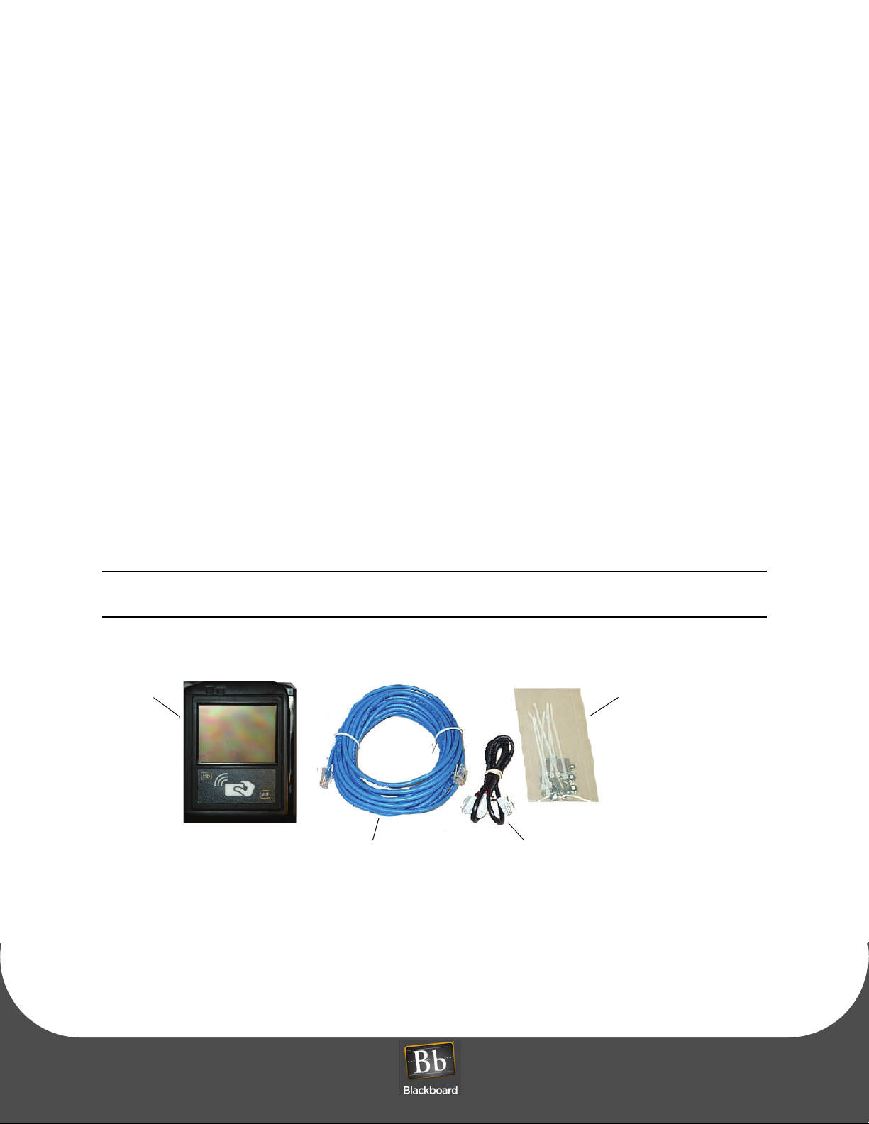
CAT5 Cable (25’)
Hardware Kit
MDB Y-Cable
Nuts, Washers,
Wires ties & Standoffs
VR4100
Reader
D OCUMENT 1277 REV 02
VENDING READER VR4100 INSTALLATION GUIDE
OVERVIEW
The Blackboard VR4100 Vending Reader supports both swipe and contactless card technology. The
vending reader allows MDB vending machines to be used with Blackboard Transaction System (BbTS),
and uses an ethernet connection to communicate to the host server. Communication of host downloads
and reader transactions use a maintained Transport Layer Security (TLS) Secure Communication Channel
to meet PCI Compliance.
The VR4100 Vending Reader can be used in any vending machine that complies with the National
Automated Merchandising Association Multi-Drop Bus (NAMA MDB) interface specification. Many vending
machines manufactured today support this interface.
A specially encoded service card is required to configure the VR4100 reader. Service cards
are ordered separately.
Figure 1: What’s included
PRINTED O CTOBER 19, 2010 1

READER FEATURES
• The reader works with a Microsoft Windows based Transaction System
• Configuration accessible via front panel (Touch Screen), CONFIG port or Web Service
• Stores up to 2500 off-line transactions
• Allows mixed card and cash vends (if supported by machine controller software)
• Interfaces to all NAMA MDB compliant vending machines
• Mounts easily in bill acceptor or comparable sized opening
• Reduces interference problems with limited size inside machine
• Two simple connections: machine controller/coin mechanism and network
• Volume can be set to off, quiet or loud
• Front panel (Touch Screen) and Web Service access can be disabled for added security
• All IP communications encrypted and authenticated for data security
• Tracks cash sales (if supported by machine controller software)
• Displays balance, account warnings, and other messages following vend
• Wireless 802.11b/g with WPA2 security (AES-CCMP encryption, PSK authentication)
O VERVIEW
For specifications, see: Reader Specifications (Page: 21).
OBJECTIVES
After reading this guide you can:
• Install the vending reader • Configure the vending reader
• Test the vending reader • Reset reader factory defaults
PRINTED O CTOBER 19, 2010
2
V ENDING READER VR4100 INSTALLATION GUIDE
1. Configure the reader in BbTS.
See: the Transaction System Administration Guide
2. Reader Installation (page 1-4).
3. Reader Configuration (page 1-7).
4. Reader Test (page 1-17).
D OCUMENT 1277 REV 02
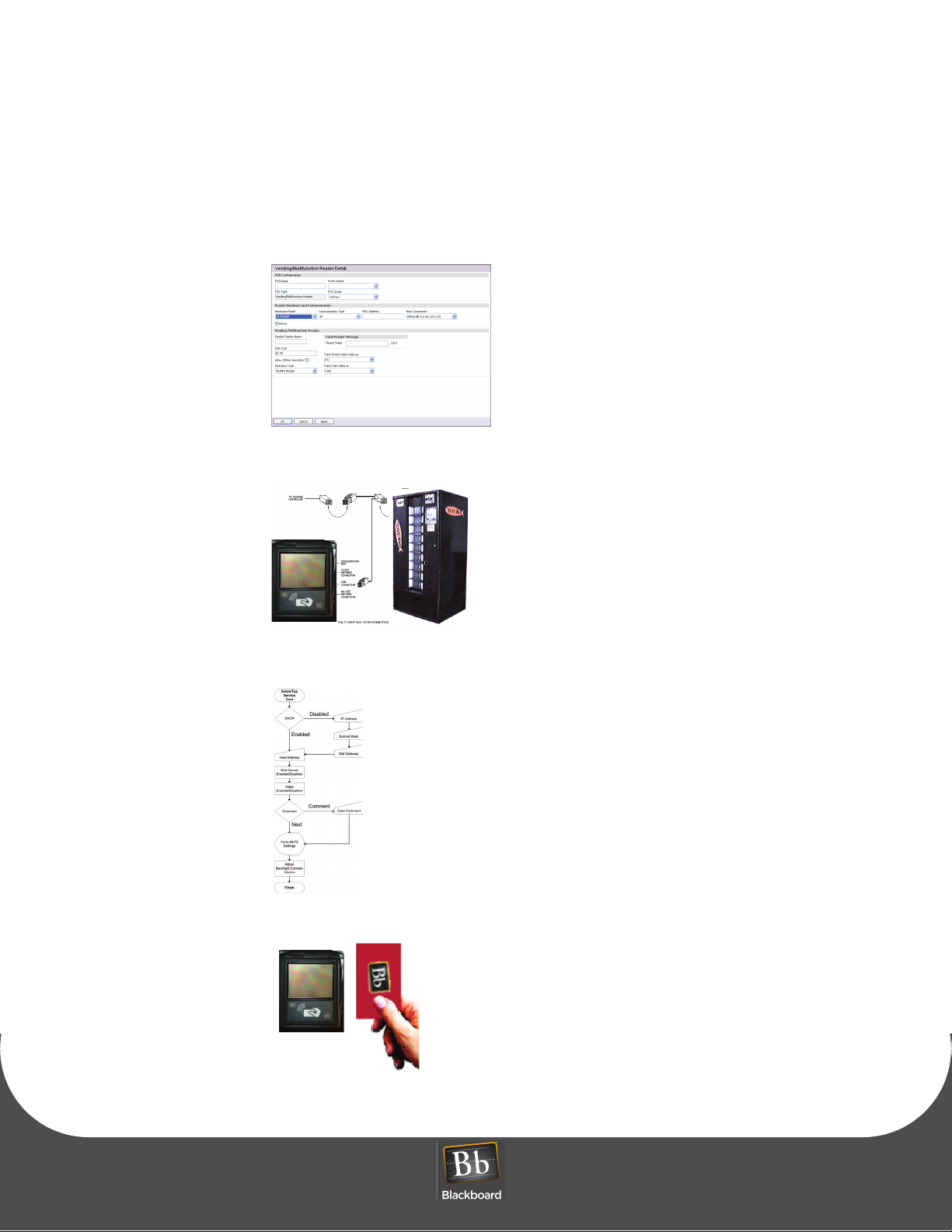
SETUP OVERVIEW
Figure 2: Setup Overview
PRINTED O CTOBER 19, 2010 3

R EADER INSTALLATION
READER INSTALLATION
All wiring should be completed by a trained electronic technician.
To install the reader
1 Power down the vending machine.
Refer to the vending machine operation manual.
2 Prepare a 3.3" x 4.2" cut-out (slightly larger allows reader to fit easily), and then drill four
3/16" holes for mounting studs in the center locations of the slots.
See: the Vending Reader Face and Mounting Dimensions (page 1-5).
If replacing an existing bill acceptor, remove the bill acceptor.
If installing in a pre-cut opening, remove the filler plate.
3 Slide the face of the reader through the opening from the inside of the machine.
If using a mounting plate, slide it over the face of the reader from the outside of the machine.
4 Install four flat washers and four nuts or threaded standoffs onto the threaded studs to secure the
reader.
If installing in a non-conductive panel in the vending machine (such as a plastic front panel), a
customer supplied ground wire should be connected from one of the mounting studs to a grounded
metal part inside the machine.
Data cables are susceptible to electrical noise that can corrupt data. Avoid routing cables near
electrical equipment, including fluorescent lights, compressors, and motors.
PRINTED O CTOBER 19, 2010
4
 Loading...