

Transact Campus LWI30XX001 Users Manual

LC3000 Laundry System
Installation and Setup Guide
The following information applies to wired LC3000 systems equipped with LCM20s only.
Blackboard Inc. LC3000
Tested To Comply
With FCC St andards
FOR HOME OR OFFICE USE
This Class A digital apparatus complies with
Canadian ICES-003
The following information applies to wireless systems equipped with LWIs and LE3/BRIDGES only.
This device complies with Part 15 of the FCC Rules. Operation is subject to the following two conditions: (1) This
device may not cause harmful interference, and (2) th is device must accept any interference received, including
interference that may cause undesired operation.
Part 15.21: Changes or modifications not expressly approved by the party responsible for compliance could void the user’s
authority to operate the equipment.
NOTE: The manufacturer is not responsible for any radio or TV interference caused by unauthor ized modifications to this
equipment. Such modifications could void the user’s authority to operate the equipment.
Date: 9-9-05 Doc. No.: 1135
Copyright © 2005 Blackboard Inc.® All rights reserved. No part of this publication may be reproduced or used
in any form or by any means—graphic, electronic, or mechanical including photocopying, recording, taping, or
information storage and retrieval systems—without the express written permission of Blackboard Inc.
Information contained in this document is subject to change without notice.

TABLE OF CONTENTS
5OVERVIEW
8 Laundry System Components
9 Laundry System Installation Overview
10 INSTALL AND CONFIGURE LC3000
10 LC3000 Laundry Reader Installation
11 Install the LC3000 Enclosure
12 LC3000 Laundry Reader Configuration
14 Configure LC3000 Reader Using Front Panel Keyboard
14 Configure LC3000 Reader Using RS-232
15 Configure LC3000 Reader Using Telnet
16 WIRED LAUNDRY MACHINE INTERFACE INSTALLATION
T ABLE OF CONTENTS
T ABLE OF CONTENTS
16 LE3/PSENCL and LCM20 Installation
16 Install the LCM20 Board in the LC3000
17 Install LE3/PSENCL (if required)
18 Connect External LCM20 to LC3000 and laundry machines
19 LCI Laundry Machine Interface Installation
19 Install Maytag LCI3010 in Laundry Machine
20 Install Alliance/Speed Queen LCI3020 in Laundry Machine
21 Install Whirlpool LCI3030 in Laundry Machine
23 WIRELESS LAUNDRY MACHINE INTERFACE INSTALLATION
24 Wireless Laundry System Installation Overview
24 Mount the LE3/BRIDGE
25 Configure the LE3/BRIDGE Wireless Module
25 Configure the LWI30XX for Laundry Machines
26 Install the LWI30XX in Laundry Machines
31 APPENDIX
31 Reader Operations
31 Laundry Reader Usage
34 Reader Menus and Settings
34 Manager Card
38 Laundry Component Dimensions and Weight
39 Features
Laundry Installation and Setup Guide 3

40 Default LC3000 Configuration Settings
40 Restore Default Settings
41 Error Messages (Unix only)
41 Error Messages (windows only)
42 Retrofits
42 MW9010/MW9012 LCR Retrofits (For Wired Laundry Centers only)
42 Danyl Retrofits
42 LC3000 Drill Template
T ABLE OF CONTENTS
T ABLE OF CONTENTS
Laundry Installation and Setup Guide 4

O VERVIEW
O VERVIEW
OVERVIEW
This manual provides instructions for selecting, installing, and configuring the Blackboard Laundry System, using the LC3000
Laundry Reader. Recommendations on selecting an installation location are included. Wiring diagrams show you how to connect the LC3000 Laundry System.
The LC3000 Laundry Reader activates and monitors washers and dryers across a laundry center network. The
LC3000 is designed to work with the Blackboard Transaction System (BbTS) and provides user interface through a
display, keypad, and mag-stripe reader. The network connections are 10/100 Base-T or RS-485.
The LC3000 supports new installations for wired or wireless laundry centers. Information for retrofits is available in the
“Appendix” on page 31.
Laundry Installation and Setup Guide 5
O VERVIEW
O VERVIEW
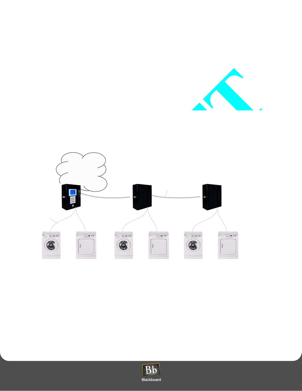
Wired Solution
The wired solution supports up to 60 laundry machines (see Figure 1 below). In laundry centers with 20 or fewer
machines, you only need a single LCM20, which is installed inside the LC3000 enclosure. If your laundry center
supports more than 20 machines, a multiplexer (an LCM20) and an enclosure (LE3/PSENCL) are needed for each
additional set of 20 laundry machines. The LC3000 reader can support a maximum of three (3) multiplexers.
A machine interface (an LCI), which is a wiring harness that communicates with the laundry machine controller, is
connected to a cable within a multiplexer (LCM20). This machine interface must be installed in every laundry machine
to facilitate communication between the laundry machines and the LC3000 laundry reader unit. Several models of
machine interfaces are available. Use Table 1 (on page 8) to determine the correct machine interface (LCI) model
number, based on the manufacturer and model of your laundry machines.
4-conductor cable
(400’ max)
1 ---------------------- 20 21 -------------------- 40 41 -------------------- 60
Campus
Network
Laundry Reader
w/
Multiplexer
(LC3000)
(LMC20)
Laundry Center Interface
Belden 5502UE cable
or equivilant
Multiplexer
w/
Enclosure
(LCI)
installed in each machine
(LCM20)
(LE3/PSENCL)
Multiplexer
w/
Enclosure
(LCM20)
(LE3/PSENCL)
Figure 1: Wired Laundry Center Solution
Laundry Installation and Setup Guide 6
O VERVIEW
O VERVIEW
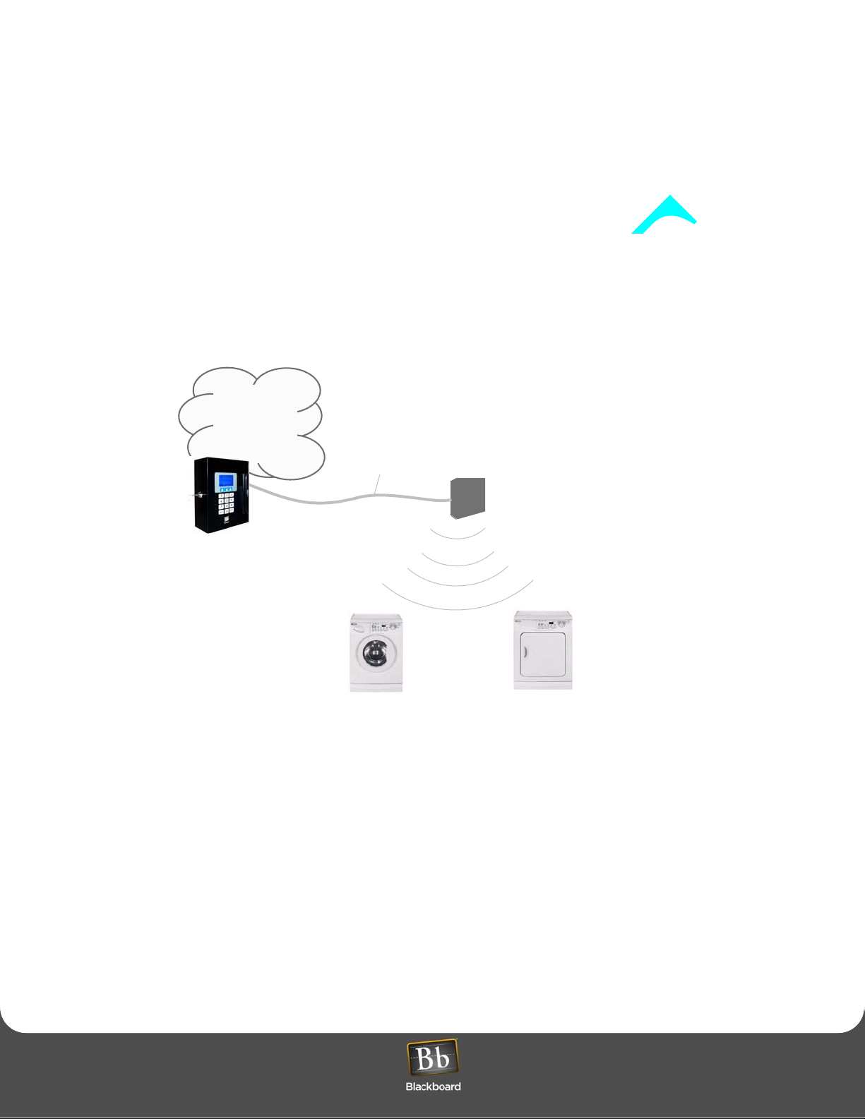
Wireless Solution
The wireless solution supports up to 60 laundry machines, using a wireless bridge (L E3/BRIDGE). See Figure 2 below.
A laundry wireless interface (LWI) must be installed in every laundry machine to facilitate communication between the
laundry machines and the LC3000 Laundry Reader. The LWI includes a Wireless Interface Module and a wiring
harness. Several models of LWIs are available. Use Table 1 (on page 8) to select the correct LWI model numb er based
on the manufacturer and model of your laundry machines.
Campus
Network
Belden 5502UE cable
or equivilant
Laundry Reader
(machines 1 - 60)
(LC3000)
(60 feet)
1 ------------------------------------------ 60
Laundry Wireless Interface
Wireless Bridge
(LWI)
installed in each machine
(LE3/BRIDGE)
Figure 2: Wireless Laundry Center Solution
Laundry Installation and Setup Guide 7
L AUNDRY SYSTEM COMPONENTS
L AUNDRY SYSTEM COMPONENTS
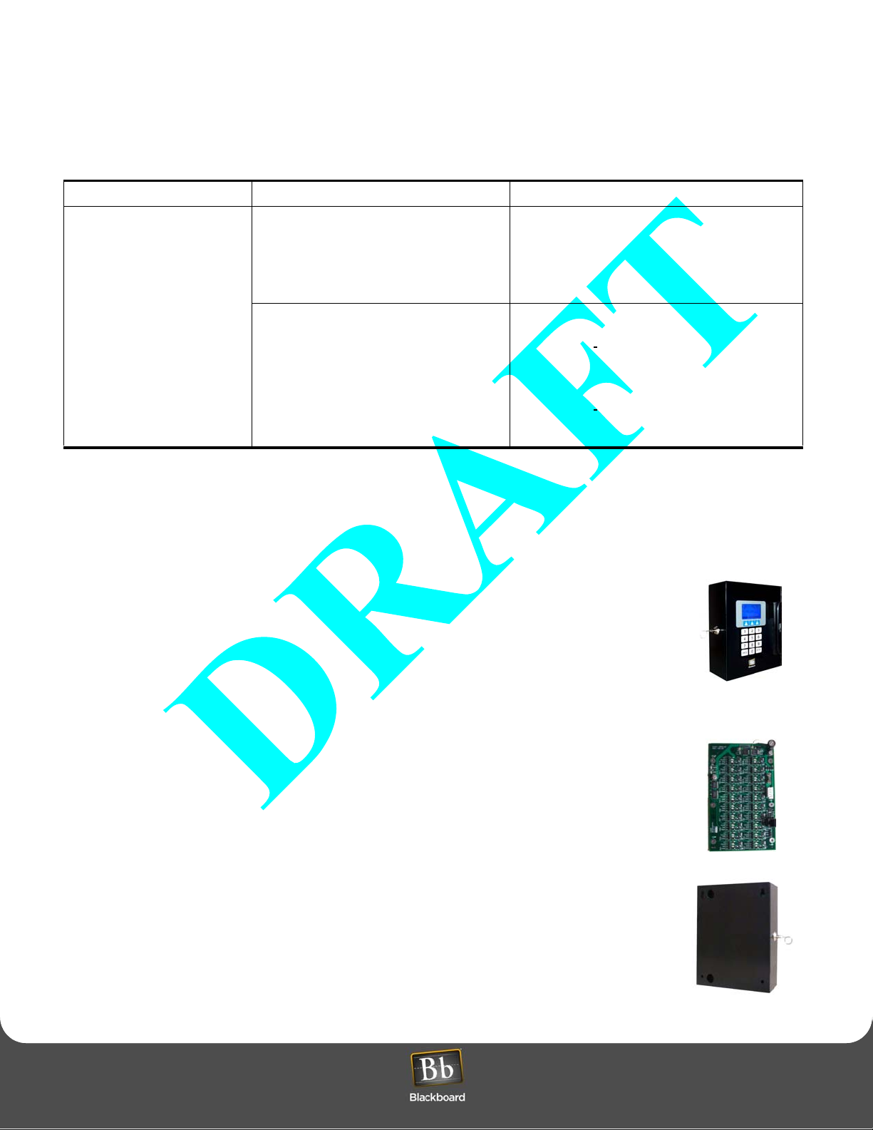
LAUNDRY SYSTEM COMPONENTS
Common Component Wired Interface Components Wireless Interface Components
Laundry Reader (LC3000):
Supports up to 60 machines*
using up to 3 Multiplexers
(wired); or up to 7 Wireless
Bridges (LE3/BRIDGE) per
Laundry Reader; up to 60
machines within 60 feet
• Laundry Multiplexer (LCM20): 1 per 20
wired machines*; first LCM20 is included
in the LC3000 enclosure; second and third
LCM20s require LE3/PSENCL.
• Enclosure (LE3/PSENCL): (power
supply/enclosure) 1 per external LCM20.
• Wired Interfaces (LCI)
Wireless Bridge (LE3/BRIDGE): 1 per laundry
room; up to 7 Bridges per Laundry Reader; and up
to 60 machines* can be supported within 60 feet.
• Wireless Interfaces (LWI)
• LCI3010: Mayt ag interface, wired: 1 per
machine or complete stacked unit
• LCI3020: Speed Queen interface,
wired; 1 per machine or half stacked
unit.
• LCI3030: Whirlpool interface, wired; 1
per machine or half stacked unit.
• LWI3010:
machine or complete stacked unit.
• LWI3020: Speed queen interface, wireless; 1
per machine or half stacked unit.
• LWI3030:
machine or half stacked unit.
Maytag interface, wireless; 1 per
Whirlpool interface, wireless; 1 per
Table 1: Laundry System Components
* count a stacked unit as two machines
The Blackboard Laundry System can communicate with most computer-controlled (debit-ready) mach ine s. Th is
System includes the following components:
Laundry Reader (LC3000)
The Laundry Reader is a wall-mounted card reader with a vertical swipe mag-stripe card
reader. It includes a 15-key keypad and an LCD display. It features a keyed lock to secure the
inside of the unit, along with a hinged door to access the circuit boards.
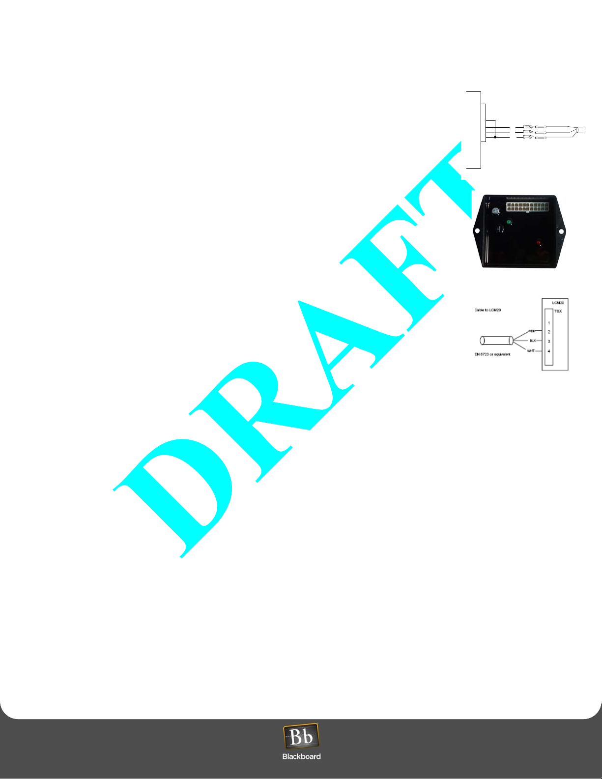
Laundry Center Multiplexer (LCM20)
The Multiplexer communicates with the LC3000 and controls up to 20 laundry machines. Up to
three LCM20 Multiplexers can be connected to an LC3000 to control a maximum of 60 laundry
machines. The LC3000 communicates to an LCM20 over an RS-485 bus.
Enclosure (LE3/PSENCL)
External Multiplexers (LCM20s), the 2nd an d 3rd Multiplexers connected to an LC30 00, require
this enclosure for mounting
Laundry Installation and Setup Guide 8
L AUNDRY SYSTEM INSTALLATION OVERVIEW
L AUNDRY SYSTEM INSTALLATION OVERVIEW
Laundry Center Interface (LCI)
The LCI is a wiring harness that attaches to the control circuitry within the laundry machine.
There are several LCI models to support machines from different manufacturers and model
types.
Laundry Wireless Bridge (LE3/BRIDGE)
The Bridge provides a wireless connection between the LC3000 and laundry machines. It
communicates with the LC3000 over an RS-485 bus and communicates with LWIs within the
laundry machines over a wireless network.
Laundry Wireless Interface (LWI)
The LWI is a wiring harness installed inside the laundry machine and interfaces with the
machine controller. There are several models of LWIs to support machines from different
manufacturers and model types.
Laundry Machine
6
5
4
3
RED
2
WHT
1
BLK
RED
WHT
BLK
LAUNDRY SYSTEM INSTALLATION OVERVIEW
1 Configure BbTS (See System Administrator Guide).
2 LC3000 Laundry Reader Installation (page 10 )
3 LC3000 Laundry Reader Configuration (page 12)
4 Wired Laundry Machine Interface Installation (page 16) or
Wireless Laundry Machine Interface Installation (page 23)
Laundry Installation and Setup Guide 9

I NSTALL AND CONFIGURE LC3000
I NSTALL AND CONFIGURE LC3000
INSTALL AND CONFIGURE LC3000
LC3000 LAUNDRY READER INSTALLATION
Select a mounting method based on the application and the network mode of the reader. The LC3000 enclosure is
designed to mount on a wall: it can be flush-mounted (wiring can come from the interior of the wall); or it can be
surface-mounted (wiring can run through conduit on the exterior of the wall).
LC3000 Mounting Location Considerations
Use the following criteria to select the best mounting location for the LC3000:
Connect to 120 VAC @ 60 Hz. Connect only to a 15A maximum branch circuit protection or equivalent.
Use a circuit breaker or switch to disconnect power when installing or removing the LC3000.
• 120VAC power a vailability
• Network communications availability (RS-485 or 10/100 Base T)
• Wiring distance limitations
RS-485 Communications 4000' total per loop
10/100 Base-T Communications 300'
• Ease of cable routing to Laundry machines (if wired configuration)
• Installation height regulations
Mounting Requirements
Mounting hardware, .25” appropriate to surface.
Laundry Installation and Setup Guide
10
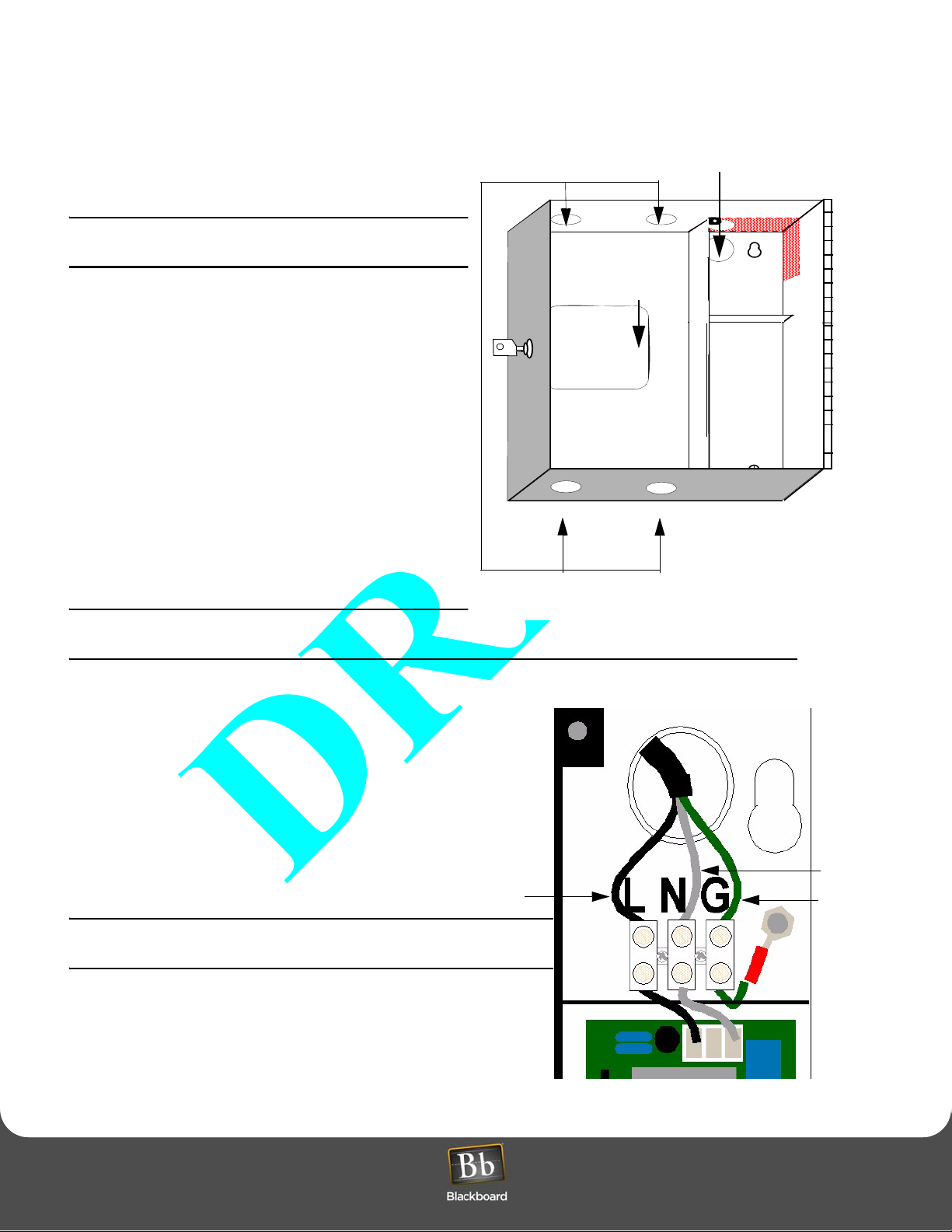
Preparing the Enclosure
ACMAIN
Mount
Mount
Before mounting the enclosure, remove all
necessary knockouts to route wires and/or attach
conduits.
Remove only the knockouts required for your
installation.
• All knockouts are dimensioned for 1/2” conduit
fittings.
Flush-mounted enclosure: If installing a wired
laundry center, route machine wires through the
“3x3” cutout.
Surface-mounted enclosure: Remove conduit
knockouts, located on the top and bottom of the
enclosure, to route wire to the laundry machines.
• The enclosure provides two knockouts, in the upper
right, for power.
Flush-mounted enclosure: Remove the knockout
on the back side.
Surface-mounted enclosure: Remove the
knockout on the top.
LC3000 LAUNDRY READER INSTALLATION
LC3000 LAUNDRY READER INSTALLATION
AC Main Power
Flush-mount
“3x3” cutout
Surface-mount knockouts
Maintain 1/4" separation from AC wiring to other
wiring.
Install the LC3000 Enclosure
1 Inside the LC3000, remove the power supply cover
to access the upper right mounting hole.
Protect power supply from debris while mounting the
enclosure.
2 Secure the enclosure to a wall using hardware
appropriate for the wall material.
Mounting holes accept up to 1/4” hardware.
Disconnect external AC power when installing any
wiring.
Line
Figure 3: Knockout areas
Neutral
Ground
Figure 4: Power Supply Installation
Laundry Installation and Setup Guide 11

LC3000 LAUNDRY READER CONFIGURATION
LC3000 LAUNDRY READER CONFIGURATION
3 Strip back the insulation on the AC wire .28" to prevent bare wire from being exposed when installed in the AC
terminal block.
4 Install the appropriate wires into the AC terminal block, as shown in Figure 4, tighten the screws to 5 - 7 in-lbs., and
replace power supply cover.
Ensure all 120VAC wiring is confined within the po wer supply comp artment when the cover is reinst alled to
maintain UL compliance.
5 Reconnect external AC power.
Maintain 1/4" separation from AC wiring to other wiring.
6 Connect to Network.
The LC3000 board provides both 10/100 Base-T TCP/IP and RS-485 network connections for communications
with the BbTS (NP, Network Processor). Select a connection based on the local network.
Once you connect the LC3000 to the network, configu re th e L C300 0 for the networ k. Re fe r to the LC3000
Laundry Reader Configuration (page 13) for details on configuring the unit.
LC3000 LAUNDRY READER CONFIGURATION
Configuration Methods
The Laundry Reader must be configured to interface with the BbTS network. Configure the Reader using either the
front panel of the Reader or the configuration port (see Figure 5: LC3000 Laundry Reader Configuration (page 13).
Future configuration modifications can be one using Telnet, if enabled.
Default Settings
The LC3000 Controller Unit default settings are:
• DHCP enabled
• NP (host) IP address assigned by DHCP server
Configure the LC3000 Laundry Reader to interface with BbTS, using one of three modes:
• Front Panel Keyboard
• Config Port - provides for RS-232 connection to a computer with Hyperterminal software
• Telnet via IP if using Ethernet connections
Laundry Installation and Setup Guide 12
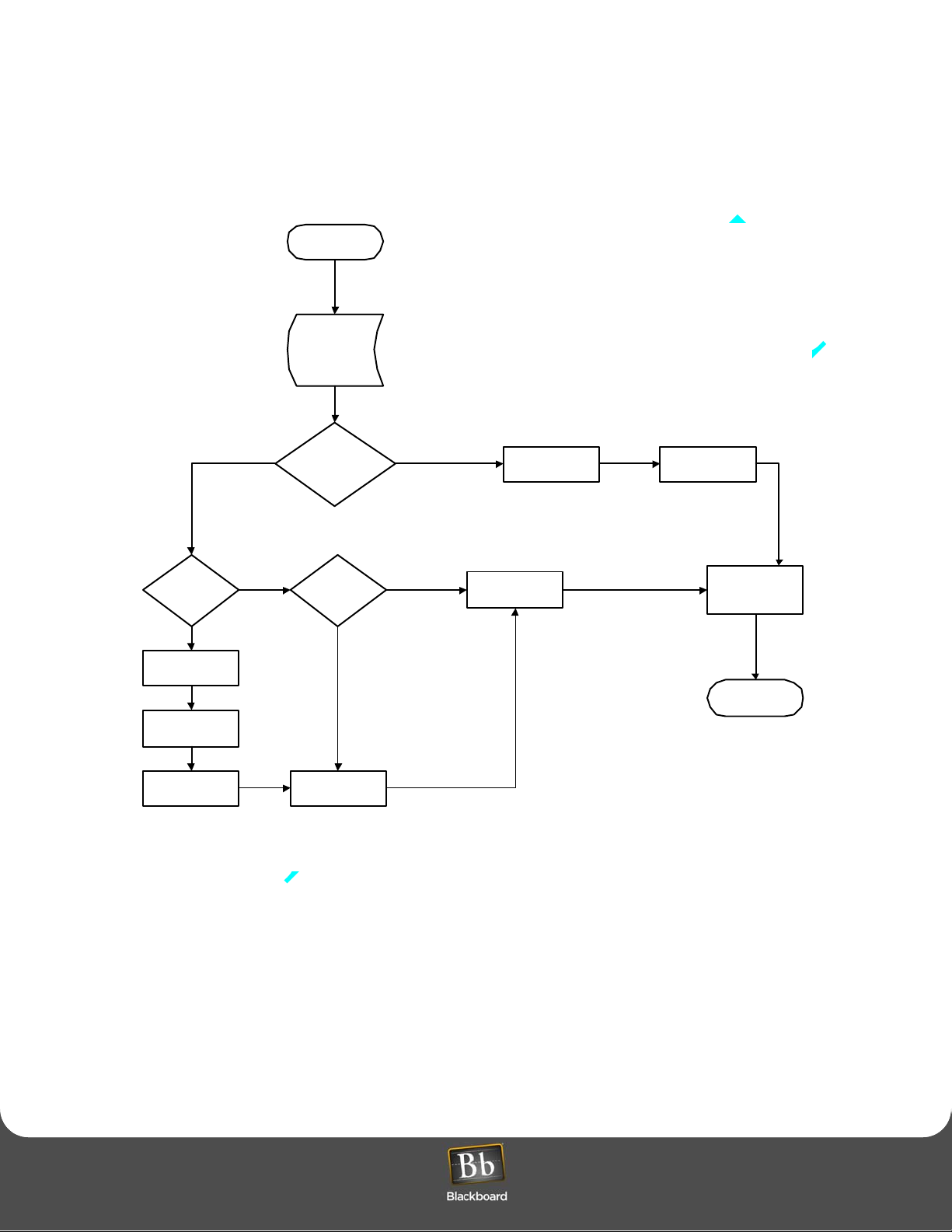
LC3000Config
MAC Address
IP Address
DHCP Status
LC3000 LAUNDRY READER CONFIGURATION
LC3000 LAUNDRY READER CONFIGURATION
IP Communica ti o ns
Enabled
DHCP
Disabled
IP Address
Subnet Mask
Default Router/
Gateway
Communication
Mode
Host DHCP Telnet Enabl e
Host IP Address
RS-485 Communications
Reader Address Baud Rate
Disable
Service Card
Enabl e
Save
Figure 5: LC3000 Laundry Reader Configuration
Laundry Installation and Setup Guide 13
 Loading...