

Transact Campus DR4100X007 Installation Manual
AC3100
Installation Guide
"Underwriters Laboratories Inc. (“UL”) has not tested the performance or reliability of the security or
signaling aspects of this product. UL has only tested for fire, shock and/or casualty hazards as outlined in
the U.S. and Canadian (Bi-National) Standard for Safety of Information Technology Equipment, CSA C22.2
No. 60950-1-03; UL 60950-1 First Edition dated April 1, 2003. UL Certification does not cover the
performance or reliability of the security or signaling aspects of this product. UL MAKES NO
REPRESENTATIONS, WARRANTIES OR CERTIFICATIONS WHATSOEVER REGARDING THE
PERFORMANCE OR RELIABILITY OF ANY SECURITY OR SIGNALING RELATED FUNCTIONS OF
THIS PRODUCT."
Blackboard Inc. AC3100
Tested To Comply
With FCC Standards
FOR HOME OR OFFICE USE
This Class A digital apparatus complies with
Canadian ICES-003
This device complies with Part 15 of the FCC Rules. Operation is subject to the following two
conditions: (1) This device may not cause harmful interference, and (2) this device must accept any
interference received, including interference that may cause undesired operation. Part 15.21:
Changes or modifications not expressly approved by the party responsible for compliance could void the
user’s authority to operate the equipment.
NOTE: The manufacturer is not responsible for any radio or TV interference caused by
unauthorized modifications to this equipment. Such modifications could void the user’s
authority to operate the equipment. This equipment complies with the FCC radiation exposure
limits set forth for an uncontrolled environment. End users must follow the specific operating
instructions for satisfying RF exposure compliance. The antenna(s) used for this transmitter
must be installed to provide a separation distance of at least 20 cm from all persons and must
not be co-located or operating in conjunction with any other antenna or transmitter.
PRINTED APRIL 14, 2011

Contents
AC3100 INSTALLATION GUIDE
4 AC3100 Installation
4 Mount the AC3100
6 Connect the AC3100 to the power source
7 Connect the AC3100 to the network
8 AC3100 Communication Configuration
10 Configure Communication using Front Panel & Service Card
11 Configure Communication using RS-232 or Telnet
13 AC3100 Transaction Process
13 Deposit Funds to an Existing Account
13 Purchase a Visitor Card
13 Check Account Balance
14 AC3100 Manager Card Functions
14 Display/print transaction totals
14 Terminal setup
14 Display device status information
14 Perform diagnostic functions
15 AC3100 Maintenance
15 Fill the Card Dispenser
15 Empty the Bill Box
17 Install the Paper Roll
20 Component Replacement
20 Replace the Power Supply Fuses
23 AC3100 Features & Specifications
23 AC3100 Features:
23 AC3100 Specifications:
24 BbTS Universal Edition Changes
PRINTED APRIL 14, 2011
I

Figures
Figure 1-1 What You Get .............................................................................................1
Figure 1-2 AC3100 Reader Details..............................................................................3
Figure 1-3 Mounting Illustration ...................................................................................5
Figure 1-4 RS-485 Reader Pinout ...............................................................................7
Figure 1-5 Configuration Flowchart .............................................................................9
Figure 1-6 Out-Of-Service Codes ..............................................................................10
Figure 1-7 Configuration Command Reference.........................................................12
Figure 1-8 Bill Box Removal ......................................................................................16
Figure 1-9 AC3100 Paper roll ....................................................................................18
Figure 1-10 Paper Roll Cut-off.....................................................................................18
Figure 1-11 Paper Entry Opening................................................................................19
Figure 1-12 AC3100 Fuse Locations...........................................................................20
Figure 1-13 AC3100 Components...............................................................................21
Figure 1-14 Lock Lubrication .......................................................................................22
PRINTED APRIL 14, 2011
II
AC3100 INSTALLATION GUIDE
AC3100 Reader
Bill Box keys
Spare Bill Box
Paper rolls
Door lock keys
Hardware kit
D OCUMENT 1353 REV 01
AC3100 INSTALLATION GUIDE
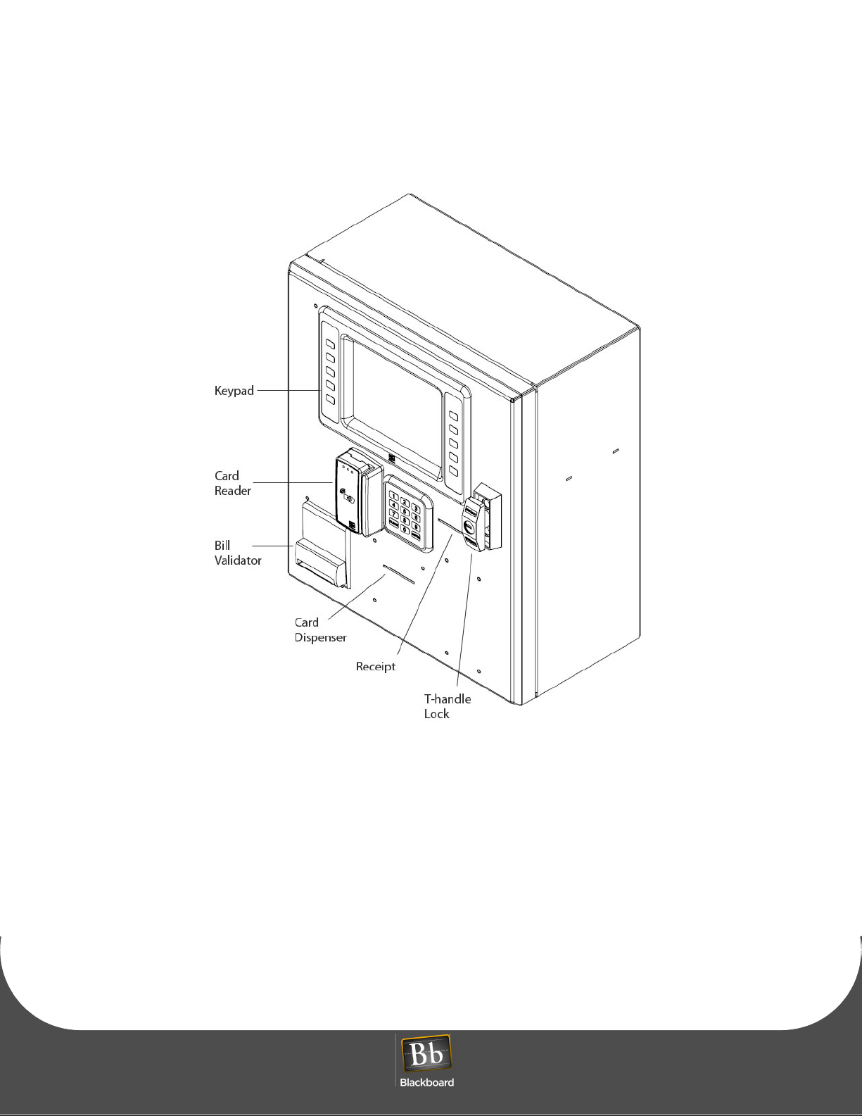
The Blackboard AC3100 enables cardholders to deposit to accounts, check balances, and purchase visitor
cards. The user interface utilizes an LCD display, keypad, and a combination mag-stripe and contactless
reader. Both the UNIX Edition and Universal Edition versions of the reader support user configurable
background color, text color, and banner images. Communication of host downloads, and reader
transactions use a maintained Transport Layer Security (TLS) Secure Communication Channel to meet
PCI Compliance.
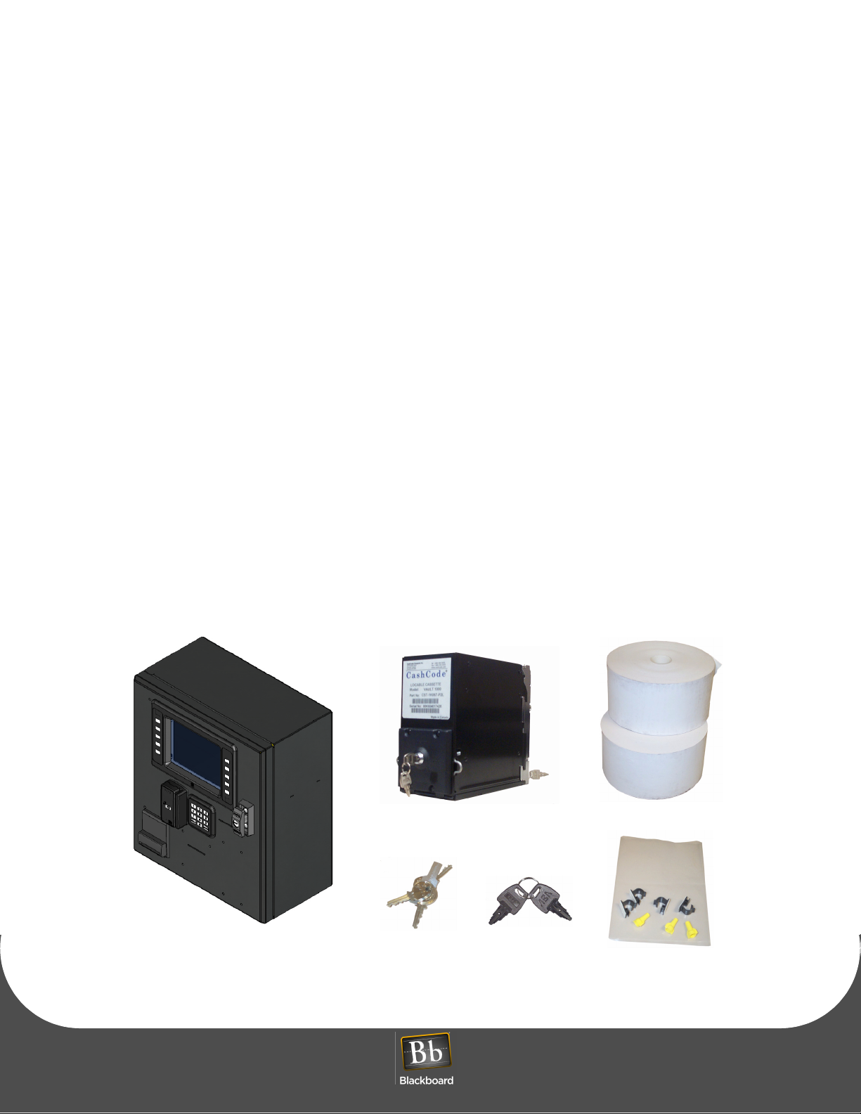
WHAT YOU GET
The following items are included with each AC3100:
• (2) bill boxes (one installed)
• (2) paper rolls
• (4) door lock keys
• (4) bill box key sets
• (1) hardware kit
Figure 1-1 What You Get
PRINTED APRIL 14, 2011 1

The AC3100 connects to the Universal Edition Host via 10/100 Base-T or RS-485 through an IP Converter
(IPC). In UNIX Edition, the AC3100 optionally connects via RS-485. This unit replaces the Value Transfer
Station (VTS) on the UNIX Edition Host, and the Card Management Center (CMC) on the Universal Edition
Host.
The AC3100 accepts unattended deposits into existing cardholder accounts, and must be online to be
operational.
The following topics are covered in this document:
• AC3100 Installation (page 1-4)
• AC3100 Communication Configuration (page 1-8)
• AC3100 Transaction Process (page 1-13)
• AC3100 Maintenance (page 1-15)
• Component Replacement (page 1-20)
• AC3100 Features & Specifications (page 1-23)
PRINTED APRIL 14, 2011
2
AC3100 INSTALLATION GUIDE
D OCUMENT 1353 REV 01
Figure 1-2 AC3100 Reader Details
PRINTED APRIL 14, 2011 3

AC3100 INSTALLATION
AC3100 INSTALLATION
Mount the AC3100
The AC3100 can be surface mounted on a wall, recessed into a wall, or mounted on a pedestal. At least
four 3/8” diameter metal fasteners should be used to mount the enclosure. The installer is responsible for
ensuring the unit is securely installed to prevent theft.
WARNING: Use caution when opening the door without the enclosure secured to a wall or
pedestal. The weight of the door when open can cause the unit to tip over and cause injury.
Ensure the unit is securely mounted prior to operation.
To mount the AC3100
1 Decide where to mount the unit, and how to route power.
Conduit knockouts are located in the junction box located in the lower left of the enclosure. Power
wiring must enter the unit within the junction box.
2 Decide how to route the network wiring entering the unit.
NOTE: To eliminate risk of electrical shock or injury, do not route the network cable through
the junction box.
3 Punch or drill mounting holes in either the back or the bottom of the unit, based on the application.
4 Punch or drill a hole in the back or bottom of the cabinet to route the network cable.
This hole must be large enough to accommodate the RJ45 connector.
5 Securely mount the unit, see: Figure 1-3 Mounting Illustration (page 5).
PRINTED APRIL 14, 2011
4
AC3100 INSTALLATION GUIDE
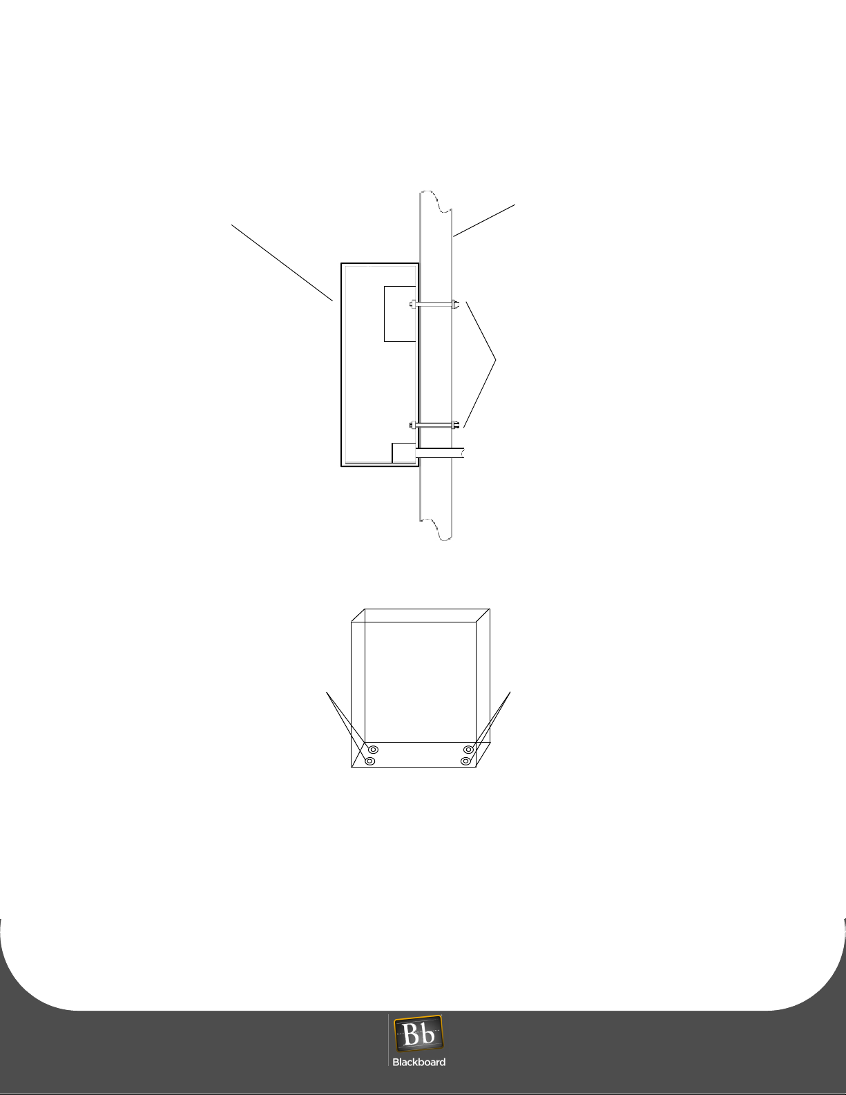
AC3100
Wall
anchor
bolts
pedestal mount
3/8” bolt & washers3/8” bolt & washers
D OCUMENT 1353 REV 01
Figure 1-3 Mounting Illustration
PRINTED APRIL 14, 2011 5
 Loading...