

Trango Systems VTX5900 User Manual

FALCON PLUS SERIES
5.8 GHz Wireless Video/Audio/Alarm/Data Transmission System
Installation and Operating Instructions
1• Verify proper operation of camera and monitor/event recorder using coaxial cable prior
to installing wireless link.
2• Install transmitter (VTX5900) and receiver (VRX5900) units in desired location to a steel
pole per installation drawing. The pole must be securely mounted so that it does not move,
and may be from 1.5” to 3” in diameter.
3• Install antennas above the enclosures.
WARNING
WARNING
WARNINGWARNING
USE EXTREME CARE WHEN INSTALLING ANTENNAS NEAR POWER LINES.
4• Slide heatshrink over antenna cable. Tighten antenna cable to receiver and transmitter.
Heat up the heatshrink until it contracts around the connector junction.
5• Connect video, audio, power, alarm, PC interface cables as needed to units through
flanges. Tighten flanges to allow small air gap at bottom of enclosure.
IMPORTANT NOTE:
Power adapter must be kept dry.
6• Verify that LEDs are lit up and transmitter and receiver are on same channel.
7• Tighten lid of enclosure down.
8• To help protect against potential lightning damage, use a lightning surge arrestor in line
with all cabling entering a structure a nd at the antenna input.
CAUTION
CAUTION
CAUTIONCAUTION
DO NOT APPLY POWER TO THE TRANSMITTER UNLESS THE ANTENNA IS
CONNECTED. PERMANENT DAMAGE MAY RESULT.
Copyright © 1999 Trango Systems, Inc. All rights reserved.
1

Congratulations on choosing Trango Systems, Inc. to fulfill your wireless video needs. Unpack
your system carefully. If any items are missing, notify your sales representative. If an item
appears to be damaged from shipment, replace it in its packing material and notify the shipper.
Save the packaging for further storage of the equipment.
Service:
If the unit ever needs repair service, contact your Trango Systems, Inc. distributor for
return authorizatio n and shipping inst ruc tion s.
FCC Information:
Note: This equipment has been tested and found to comply with the limits for a Class B
digital device, pursuant to Part 15 of the FCC Rules. These limits are designed to
provide reasonable protection against harmful interference in a residential installation.
This equipment generates, uses, and can ra diate radio frequency energy, and if not
installed and used in accordance with these instructions, may cause harmful interference
to radio communications. However, there is no guarantee that interference will not
occur in a particular installation. If this equipment does cause harmful interference to
radio or television reception, which can be determined by turning the equipment off and
on, the user is encouraged to correct the interference by one of more of the following
measures:
1) Reorient the receiving antenna;
2) Increase the separation between the affected equipment and the receiver;
3) Connect the affected equipment to an outlet on a different circuit from that
which the receiver is connected to;
4) Consult the dealer and/or experienced radio/TV technician for help.
VTX2500: # NCYVTX5900
CANADA:
IMPORTANT NOTE:
Intentional or unintentional cha nges or modifications not express ly approved by the
party responsible for compliance must not be made. Any such modifications could void
the user’s authority to operate the equipment and will void the manufacturer’s
warranty.
System Description:
The FALCON PLUS Wireless Video System is a professional quality system designed
for sending composite NTSC or PAL video, audio, and alarm signals using 5.8 GHz
wireless technology. The typical FALCON PLUS system consists of a VTX5900
transmitter and antenna, VRX5900 Receiver and antenna, and power adapters. The
system is ideal for permanent or temporary video links due to its portable nature and easy
installation. It is not designed for operation while in motion.
2
Copyright © 1999 Trango Systems, Inc. All rights reserved.
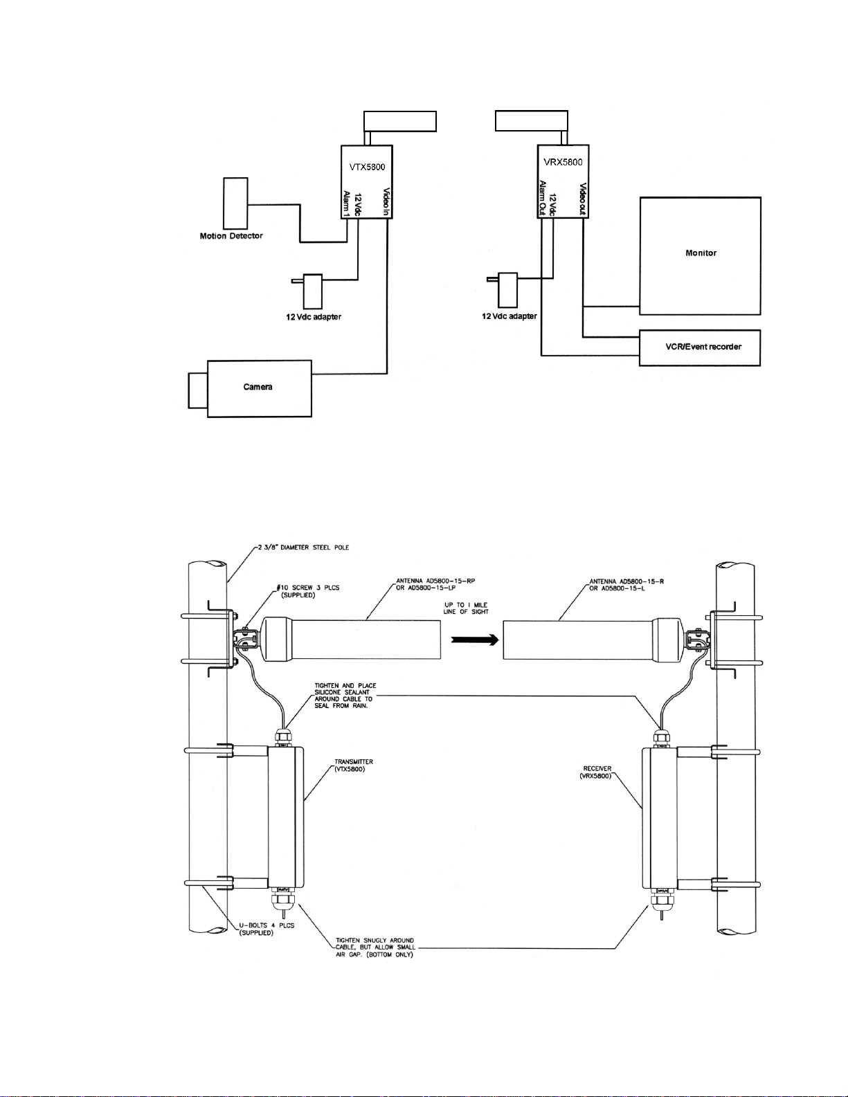
• FIGURE 1a •
Figure 1a shows the most common connection diagram for setting up a wireless video
link using the FALCON PLUS. Audio and power connections are not shown.
FIGURE 1b
Copyright © 1999 Trango Systems, Inc. All rights reserved.
3
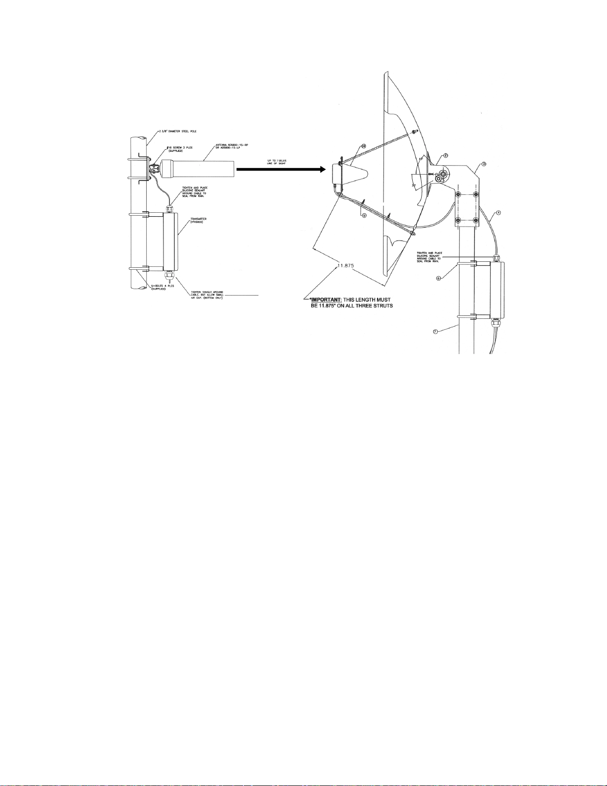
FIGURE 1c
Figures 1b and 1c show the orientation of the antennas and mounting of the enclosures.
Since the antennas are directional, they must be aligned towards each other as shown.
NOTE: Make sure that your camera and monitor/recorder work properly hardwired
before attempting to install the wireless link.
4
Copyright © 1999 Trango Systems, Inc. All rights reserved.

Installation:
The FALCON PLUS system is factory-configured for operation on channel 1 with right
and left audio operational.
To obtain the best picture quality and transmission distance, the following rules of thumb
should be followed:
1) Mount the transmitter and receiver antennas above human and mechanical traffic,
the higher the better. A 10 foot 2 3/8” diameter steel mast on top of a building is
typical. Make sure that the mast is well grounded to earth ground with an 8 AWG or
larger wire. For maximum range, the transmit and receive antennas must be 15 to 20
feet above all obstacles in the line of sight.
2) Keep the transmission path as open as possible. Objects such as walls and
metallic objects near the transmission path reflect signals and may reduce the
transmission distance.
3) Do not add additional lengths of cable to connect the receiver to the antenna as
significant losses in signal and reduced transmission range will occur.
4) Keep the cable connecting the antenna to the receiv er as sh ort as possib le.
The VTX5900 transmitter and VRX5900 receiver units come pre-mounted in a NEMA4X rated aluminum enclosure which allows mounting of the unit outdoors.
Copyright © 1999 Trango Systems, Inc. All rights reserved.
5
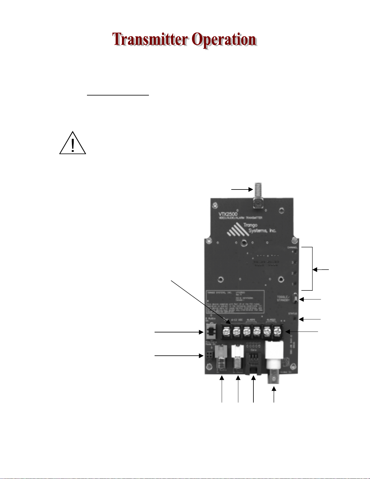
Figure 2 shows the interior of the VTX5900 transmitter and the functi ons of each control and
input/output. Each control is described in greater detail below. This card is encased in a NEMA4X rated aluminum/powdercoat enclosure. Do not remove the card from the enclosure.
IMPORTANT NOTE: The transmitter uses a non-standard jack to connect to
the transmitter antenna. Any modification to this jack may void the user’s
authority to operate the equipment and will void the manufacturer’s warranty.
CAUTION
CAUTION
CAUTIONCAUTION
DO NOT APPLY POWER TO THE TRANSMITTER WITHOUT THE
ANTENNA SECURELY ATTACHED. DO NOT APPLY VOLTAGE TO
THE ALARM PINS. DAMAGE TO THE UNIT MAY RESULT.
1. Power
2. Alarm 1/2 inputs
3. Right audio input
4. Left audio input
5. Stereo/Alarm switch
6. Data
7. Video input
8. Toggle/Standby
9. Status LED
10. Channel LEDs
11. Antenna connector
12. Header for use with optional
LC-485/422
1.
11.
10.
8.
9.
5.
Use with dry
contact closures
12.
7.6.4.3.
• FIGURE 2•
6
Copyright © 1999 Trango Systems, Inc. All rights reserved.
only.
2.

VTX5900 Transmitter Inputs & Controls:
1. POWER INPUT
Accepts a 6-12 Vdc power source such as the standard 7 Vdc adapter (Trango part
number PT07800-1), or an optional battery. The nominal current draw is 200
milliamperes. If using an adapter from a third party, use a well-regulated 300 mA
minimum output supply. Do not use the PT07800-1 to power a camera or video
distortion may occur.
2. ALARM INPUTS
These inputs are used to send alarm signals to the receiver. They sense an open or
closed state and reflect that state to the receiver whenever it changes. The alarm
inputs operate independently of each other. The transm itter is capa ble of sending
either alarms or stereo audio, selectable via the Stereo/Alarm switch.
3/4. RIGHT & LEFT AUDIO INPUTS
Designed to mate to standard RCA connectors, each input accepts 1 Vpp audio input
and is terminated with 600Ω unbalanced configuration. It is designed to interface to
“lineout” audio sources. A preamplifier must be used to connect a microphone to this
input.
5. STEREO/ALARM SWITCH
When this switch is in the “R Audio On” position, stereo audio transmission is
enabled. This permits the transmission of stereo audio with no data or alarms. When
it is in the “Alm/Data Mode On” position, R audio is disabled. In its place, either
alarms or user data (Data Pass-Through mode) are transmitted.
6. DATA INTERFACE
When connected to a personal computer via the optional CBLDAT-1 interface cable,
this input accepts serial commands that control settings in the transmitters not
available on the front panel. See the TrangoLink software section and program help
for more information. This is also the input for the RS-232 user data to be sent in
Data Pass-Through mode.
7. VIDEO INPUT
Designed to mate to a standard BNC male connector, this input accepts 1Vpp video
in both NTSC and PAL formats. This input is terminated with 75Ω. RCA-BNC
adapters are available for use with some cameras and VCRs.
8. TOGGLE/STANDBY
Depressing this switch momentarily changes the transmitter channel. Remember to
change the receiver channel as well, since it is not automatically changed when the
transmitter channel is changed. Holding the button down for 2 seconds places the
transmitter in Standby mode.
Copyright © 1999 Trango Systems, Inc. All rights reserved.
7

9/10. STATUS/CHANNEL LEDs
These LEDs display the transmitter status and current transmitter channel. There are
12 channels to choose from.
CAUTION
CAUTION
CAUTIONCAUTION
DO NOT APPLY EXTERNAL VOLTAGES TO THE ALARM INPUTS AS
PERMANENT DAMAGE TO THE UNIT MAY RESULT. USE ONLY DRY
CONTACTS WITH THESE INPUTS.
8
Copyright © 1999 Trango Systems, Inc. All rights reserved.
 Loading...