

Page 1
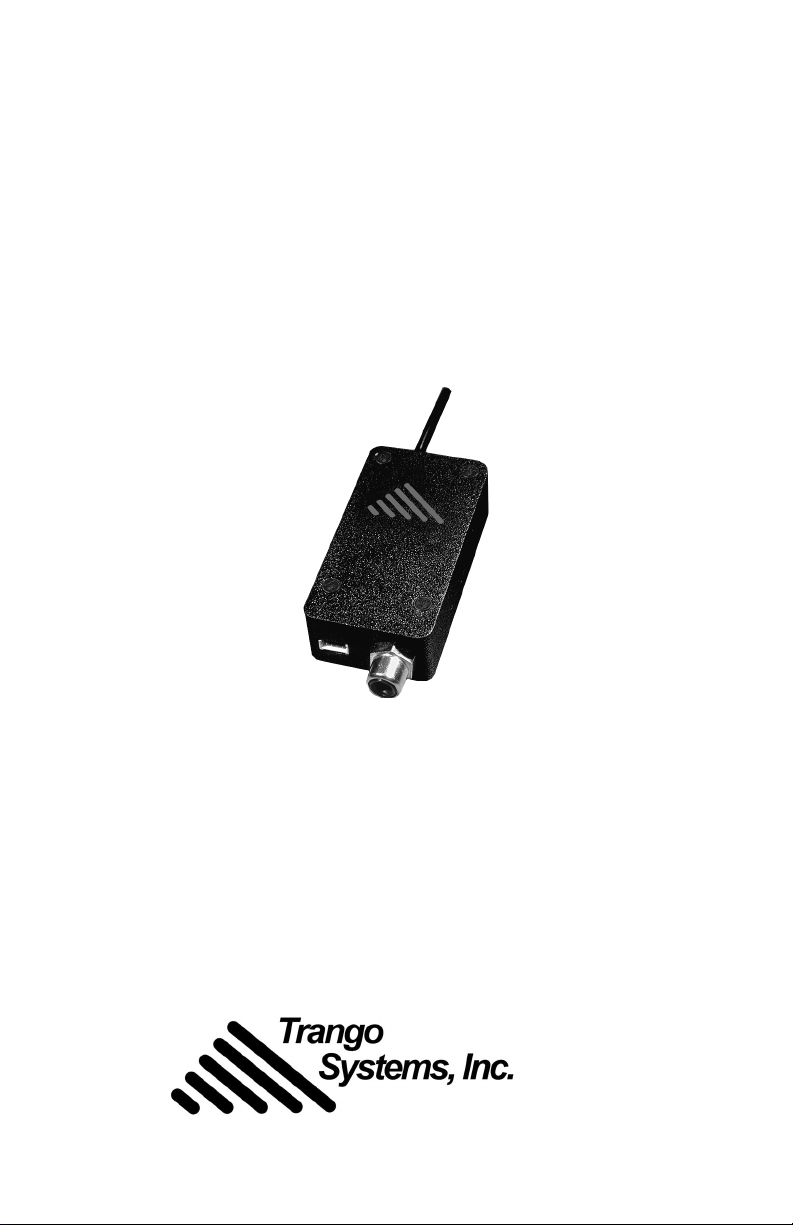
MTX-2500
2.4GHz Wireless
Video/Audio Transmitter
™
Operating Instructions
THE LEADER IN WIRELESS VIDEO
Page 2

Trango Systems, Inc.
FCC ID: NCYMTX2500MP (Canada pending)
This device complies with Part 15 of the FCC Rules.
Operation is subject to the following two conditions:
(1) this device may not cause harmful interference
and (2) this device must accept any interference received,
incluing interference that may cause undesired operation.
¤
M-MTX_A.p65
All rights reserved.
© 2001 Trango Systems, Inc.
9939 Via Pasar, San Diego CA 92126-4559
+1 858-653-3900
www.trangosys.com
MTX-2500 Operating Instructions
Page 3

The MTX-2500
™
Wireless Video/Audio Transmitter
Congratulations on choosing the MTX-2500 video/audio transmitter
from Trango Systems. When unpacking the unit, verify that the following items are present:
• MTX-2500 transmitter
• attached omnidirectional antenna
• combination input cable with connectors for power (nine-volt battery)
and audio (RCA)
If any items are missing, notify your sales representative. If an item
appears to be damaged from shipment, replace it in its packing material and notify the shipper.
Important! Intentional or unintentional changes or modifications to
this transmitter not expressly approved by the party responsible for
compliance, must not be made. Any such modifications could void the
user’s authority to operate the equipment and will void the manufacturer’s warranty.
System Description
The MTX-2500 is a miniature wireless video/audio transmitter designed
for transmitting composite NTSC or PAL video and audio signals simultaneously using 2.4GHz wireless technology.
The system is ideal for short range transmission where small size, mobility, and low current consumption are required. Due to the nature of
radio frequency (RF) transmission characteristics, the unit will perform
best while stationary, and not moving. A moving transmitter will cause
noticeable intermittent interference at the receiver, and this is normal.
rev A Trango Systems, Inc. 3
Page 4

Setup Guide
1 Prior to connecting the MTX-2500, verify proper operation of video
source and monitor/video recorder using a directly connected cable.
MONITOR
CABLE
VIDEOCAMERA
or CAMCORDER
2 Connect the power/audio cable to the MTX-2500 and attach a nine-
volt battery. Note: the unit will operate between 6 and 13.8 volts
DC, if you desire to use a different power source.
ON
1 2
MTX2500-MP
9VDC
AUDIO
VIDEO
VIDEOCAMERA
or CAMCORDER
3 Connect the video and audio sources to the RCA inputs as shown.
Audio input. Designed to mate to a standard male RCA connec-
!
tor, the audio input jack accepts 1V
audio input and is terminated
pp
with 47KΩ line configuration. A preamplifier must be used to connect a microphone to this input.
Video input. Designed to mate to a standard male RCA connec-
"
tor, this input accepts 1V
video in both NTSC and PAL formats.
pp
This input is terminated with 75Ω. RCA-to-BNC adapters are available for use with some cameras and VCRs.
Power. Nine-volt battery connector. Alternatively, a voltage be-
#
tween 6 and 13.8 volts DC may be applied. The nominal current draw
is 95 milliamperes. For alternative battery sources, the user may clip
the supplied battery lead; special care must be used to ensure that
4 MTX-2500 Operating Instructions
Page 5
the leads for positive and negative voltages are attached correctly,
otherwise the unit will not function.
Channel DIP switch. This switch controls the transmitter chan-
$
nel. Remember to change the receiver (either Eagle PLUS™ or Stingray™) channel as well, since it is not automatically changed when
the transmitter channel is changed.
60° 45°
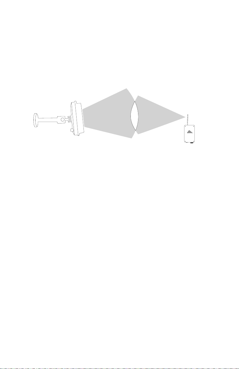
4 Move and adjust the orientation of the MTX-2500 and receiver un-
til the best picture is obtained. The best picture will be obtained
when orienting the MTX-2500 within the receiver antenna beam
width, unobstructed, as shown.
Receiver Operation
See your Stingray or Eagle PLUS documentation for proper use of video
receivers from Trango Systems, Inc.
Operational Hints
The MTX-2500 is factory-configured for operation on channel 1. The
standard transmitter is supplied with an omnidirectional (or 360°) antenna that allows the receiver to be located in any direction relative to
the transmitter within a 45° beamwidth vertically. To obtain the best
picture quality and transmission distance, the following rules of thumb
should be followed:
• Place the transmitter and receiver antennas above human and mechanical traffic but away from metallic objects.
• Keep the transmission path as open as possible. Objects such as
walls, ceilings, and metallic objects near the transmission path can
reflect signals and may reduce the transmission distance.
rev A Trango Systems, Inc. 5
Page 6

• If operating more than one system in an area, set the channels as far
apart as possible on each system (i.e. system A uses channel 1, system B uses channel 4).
Transmission Range
The system is designed to operate up to three hundred feet in most
office environments, and two thousand feet line-of-sight. Buildings with
thick steel-reinforced or concrete inner walls will reduce the maximum
obtainable range.
Service
If the unit ever needs repair service, contact your Trango Systems, Inc.,
dealer for return authorization and shipping instructions.
FCC Information
This equipment has been tested and found to comply with the limits
for a Class B digital device, pursuant to Part 15 of the FCC Rules. These
limits are designed to provide reasonable protection against harmful
interference in a residential installation. This equipment generates,
uses, and can radiate radio frequency energy and, if not installed and
used in accordance with these instructions, may cause harmful interference to radio communications. However, there is no guarantee that
interference will not occur in a particular installation.
If this equipment does cause harmful interference to radio or television reception, which can be determined by turning the equipment off
and on, the user is encouraged to correct the interference by one of
more of the following measures:
• Reorient the receiving antenna.
• Increase the separation between the affected equipment and the re-
ceiver.
• Connect the affected equipment to an outlet on a different circuit
from that which the receiver is connected to.
• Consult the dealer and/or experienced radio/TV technician for help.
6 MTX-2500 Operating Instructions
Page 7

Troubleshooting
Interference. If interference such as lines in the pictures are observed,
changing the channels may cure the problem. Also, AC generators in
close proximity to the transmitter or receiver may cause lines in the
picture. Move the unit away from the source of the interference. Note:
microwave ovens may interfere with this product.
No Picture. Check that the transmit and receive channels are set the
same. Verify all connectors are tight.
Poor Picture Quality. Raise transmitter and receiver antennas above
ground and away from obstacles and traffic, including foot traffic.
Video Too Dark. Make sure that any monitors and other peripheral
equipment connected to the video source are set to high impedance termination since the MTX-2500 transmitter has a built-in 75Ω termination.
Video Too Bright. Make sure that the receiver video output line is
terminated with 75Ω.
Please contact our Technical Support staff at 1-858-653-3900.
Specifications
Radio Section
Frequencies:
Channel 1: 2413 MHz
Channel 2: 2432 MHz
Channel 3: 2451 MHz
Channel 4: 2470 MHz
RF Output Power: 9dBm ± 1dB EIRP with
omni antenna. Meets FCC 15.249 radiated field strength of 50 mV/m at 3m.
Video Section
Input Level: 1V
Input Impedance: 75Ω unbalanced
per NTSC/PAL standard
pp
rev A Trango Systems, Inc. 7
Audio Section
Input Level: 1 V
Input Impedance: 47kΩ
Power Section
Input Voltage: 6–13.8 Vdc range,
reverse voltage protected
Current Consumption: 95±5mA typical
Max. Ripple Input: 1 V
Mechanical
Size: 1.15″W × 2.15″L × 0.64″H
Weight: 1.2 oz
Environmental
Operating Temp.: –30° to 70°C
Storage: –30° to 85°C
nominal
pp
pp
Page 8

Trango Systems technical support
online: www.trangosys.com voice: +1 858-653-3900
 Loading...