

Page 1

Ffirm
HD Mesh
HIGH DENSITY MESH SYSTEM
USER MANUAL
October 25, 2006
Revision 1.6
Page 2

Table of Contents
Preface ....................................................................................................................iii
Warranty Information ...............................................................................................iii
Contact Information..................................................................................................iii
Section 1 Introduction .........................................................................................................................................4
Overview.................................................................................................................. 4
Section 2 Hardware Overview ...........................................................................................................................5
System Contents ...................................................................................................... 5
System Radio Kits Option .......................................................................................... 6
Location of Serial Number ......................................................................................... 6
Section 2 Getting Started ...................................................................................................................................7
Opening the Box....................................................................................................... 7
Connections and Power............................................................................................. 7
Location of RJ-45/LED Port........................................................................................ 8
HD MESH Management ............................................................................................. 8
Password ................................................................................................................. 8
Browser Interface ..................................................................................................... 9
Browser Interface Login Screen ................................................................................. 9
Primary Features and Pages of the Browser Interface: .............................................. 10
Winbox (GUI) Interface........................................................................................... 11
Primary Features and Pages of the Winbox Interface: ............................................... 12
Command Line Interface ......................................................................................... 13
Telnet .................................................................................................................... 13
Section 3 Basic Configuration via Web Browser...........................................................................................14
Web Browser Interface page ................................................................................... 14
Port Web Configuration........................................................................................... 15
Port Name Web Configuration ................................................................................. 15
Interface Web Graphing .......................................................................................... 15
System Web Configuration ...................................................................................... 16
Firewall Web Configuration...................................................................................... 16
DHCP Server Web Configuration .............................................................................. 17
Upgrading RouterOS via Web Browser ..................................................................... 18
Section 4 Basic Configuration via Winbox .....................................................................................................20
Configuring an IP address ....................................................................................... 20
Configuring the Wireless Card ................................................................................. 21
Configure Firewall................................................................................................... 22
Configuring DHCP Server ........................................................................................ 23
Configuring OSPF ................................................................................................... 26
Section 5 Basic Configuration via CLI ............................................................................................................29
Launching CLI “Setup” ............................................................................................ 29
Configuring IP Address via CLI Setup ....................................................................... 30
Configuring Gateway via CLI Setup .......................................................................... 31
Configure DHCP Client via CLI Setup........................................................................ 31
Configuring DHCP Server via CLI Setup .................................................................... 32
Section 6 Default Configuration.......................................................................................................................33
Restoring Default Configuration WinBox ................................................................... 34
Restoring Default Configuration Command Line Interface.......................................... 35
Appendix A Serial Port ...............................................................................................................................36
Management serial cable......................................................................................... 36
Appendix B Specifications..........................................................................................................................37
Trango Broadband Wireless — High Density MESH page ii
Page 3
Preface
This manual covers the basic configuration and installation of the HD Mesh system, and applies to the
following part numbers:
HD Mesh 1 US Model
HD Mesh 2 International Model
The HD Mesh 1/2 system consists of an outdoor rated NEMA box (R3/ IP42) that includes a 532 Mikrotik
router board, a CM9 Wireless Access Point, one Omni 8dBi antenna, and 5 Trango PoE ports. The HD
Mesh system may be used in conjunction with any Trango Point to Point backhaul wireless broadband
equipment in a ring architecture to provided access to Wifi Hotspot as well as the local devices.
The HD Mesh system when used in conjunction with any Trango Point to Point wireless Broadband
equipment in a ring architecture will provide a reliable, redundant, high capacity Mesh style wireless
connection.
Warranty Information
HD Mesh units from Trango Broadband Wireless are warranted for one year from date of purchase.
Please see www.trangobroadband.com for a complete description of warranty coverage and limitations.
Contact Information
Corporate Headquarters Trango Broadband Wireless, a division of Trango Systems, Inc.
15070 Avenue of Science Suite 200
San Diego, CA 92128 USA
Web Sites www.trangobroadband.com www.trangosys.com
Sales Inquiries email: [email protected]
Telephone: 1-858-653-3900
Technical Support email: [email protected]
Telephone: 1-858-653-3900
Firmware Update Notices Mailing List http://www.trangobroadband.com/mailinglist/mailingListAdd.aspx
Trango Broadband Wireless — High Density MESH page iii
Page 4
HD Mesh Node
Section 1 Introduction
Trango has developed a mesh architecture that maximizes up time reliability, while minimizing the
constraints on actual data throughput. The Trango solution focuses the fail-safe functions at the most
important element of the network, the backbone. Maintaining a robust, hi-speed and redundant mesh
backbone is the most critical aspect of the network. The result is that HD Mesh provides system performance
and reliability well beyond that of competing technologies.
Overview
Trango's HD Mesh wireless backbone radios are available in 4.9, 5.3 and 5.8 GHz frequency bands.
Each HD Mesh micro cell base station includes an environmentally controlled enclosure with thermostat
controlled heater and fan, nine port router, and can support up to six additional Ethernet devices (cameras,
access points, etc.). HD Mesh is also designed to support WiMAX-ready radios and 802.11g for WiFi
hotspots. This highly flexible and scalable system is built to grow with the needs of any network and like all
Trango equipment, HD Mesh is designed for easy installation and maintenance.
The HD Mesh node box provides an innovative and easy method to create a self-healing hi-speed
backbone ring for reliable delivery of wireless broadband connectivity. The HD Mesh system is ideal for highcapacity metro backhaul, broadband access, mesh systems bandwidth injection, WiMAX systems, VOIP
traffic and IP-based video surveillance.
Trango Broadband Wireless — High Density MESH page 4
Page 5
HD Mesh Node
8d
ets
Screws, washers and Nuts
U-bolts
Section 2 Hardware Overview
The HD Mesh is an outdoor NEMA rated box that houses a Mikrotik 532 router. The router provides
OSPF functionality on the routed ports that connect to two Trango Point to Point wireless backhaul radios
which results in a layer 3 self healing wireless network. The other three Trango PoE ports can be used in
conjunction with any Trango Access Point to provide wireless connections in a Point to Multipoint format.
Each one of these PoE ports connects to an individual port on the router. This results in a unique broadcast
domain for each Access Point yielding higher performance at each cell. The router board also connects to a
MiniPCI CM9 wireless board that functions as a WiFi Access Point. This Access Point uses an Omni 8 dBi
antenna to provide a hotspot solution. The other four ports on the router can be used with any Ethernet or IP
devices and can be configured as bridge ports or router ports, for meeting different application requirements.
The HD Mesh box is powered by 110 Volts AC for HD Mesh 1 and 220 Volts AC for HD Mesh 2. The box is
design to operate in temperatures between -40º C to 60º C.
System Contents
The HD Mesh system is available in two versions:
HD Mesh 1 - US mode (110 VAC)
HD Mesh 2 - International model (220 VAC)
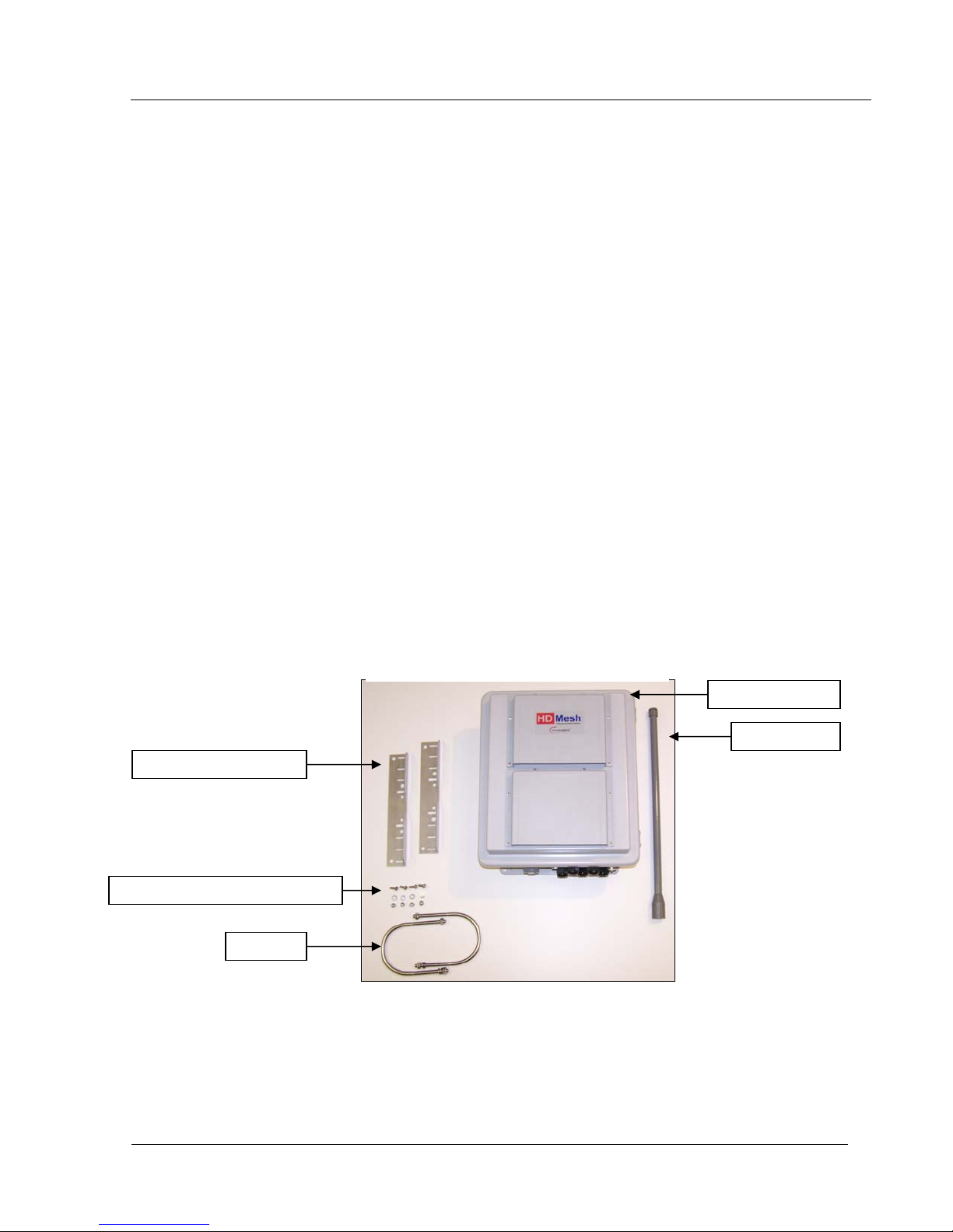
Each HD Mesh kit consists of one HD Mesh Box, one Omni 8dBi antenna, two mounting brackets, two U
bolts, four screws, four washers, and four nuts. (Figure 1)
HD Mesh Kit
Mounting Brack
HD Mesh Box
Bi Omni
Figure 1
Trango Broadband Wireless — High Density MESH page 5
Page 6
HD Mesh Node
System Radio Kits Option
HDM5010-EXT: Includes 2Atlas5010-EXT 5 GHz radios, connectorized for external antennas
HDM5010-INT: Includes 2 Atlas5010-INT 5 GHz radios, with integrated 23dBi antennas
HDM4900-INT-18: Includes 2 Atlas4900-INT-18 4.9GHz radios with integrated 18dBi antennas
HDM4900-INT-22: Includes 2 Atlas4900-INT-22 4.9GHz radios with integrated 22 dBi antennas
HDM4900-EXT: Includes 2 Atlas4900-EXT 4.9GHz radios, connectorized for external antennas
Location of Serial Number
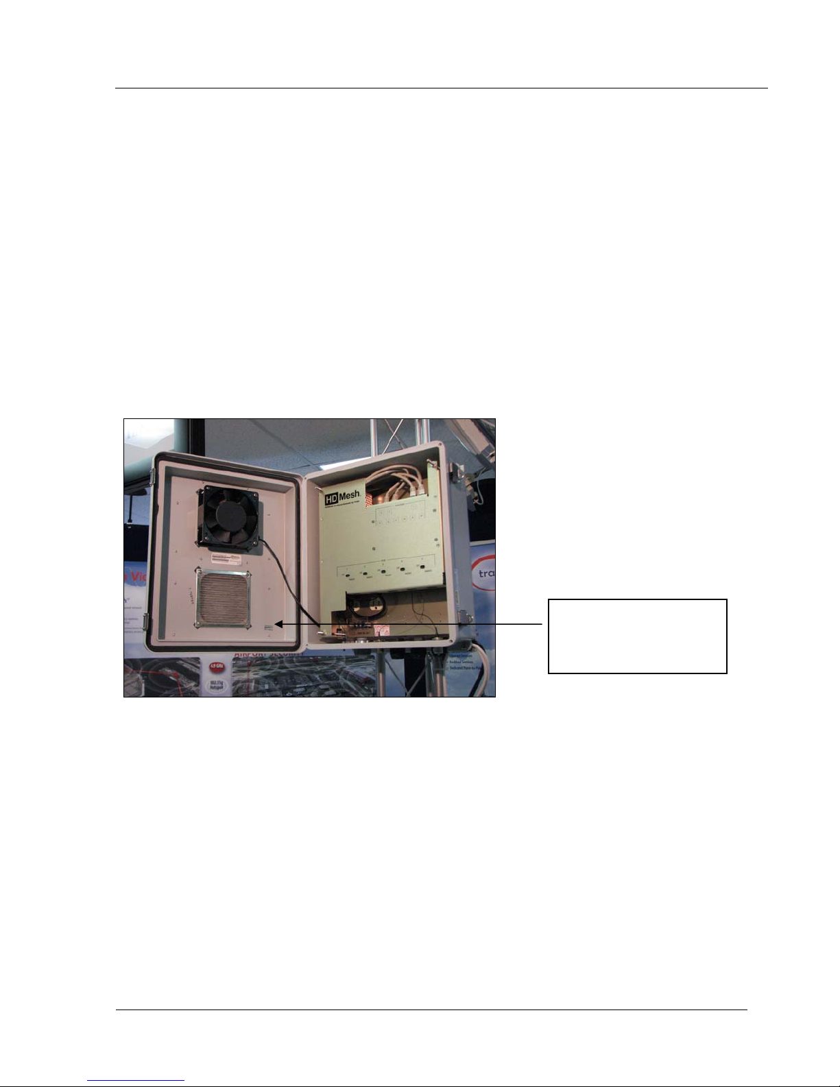
The serial number can be found on the inside of the door of the HD Mesh box. (Figure 2)
Figure 2
TRANGO BROADBAND WIRELESS
HD MESH-1
REV: A
SERIAL: HDM10XXXX
Trango Broadband Wireless — High Density MESH page 6
Page 7
HD Mesh Node
Section 2 Getting Started
It is always a good idea to first provision and test the equipment on the bench before deploying them in the
field. This is a particularly useful exercise for the novice user.
Opening the Box
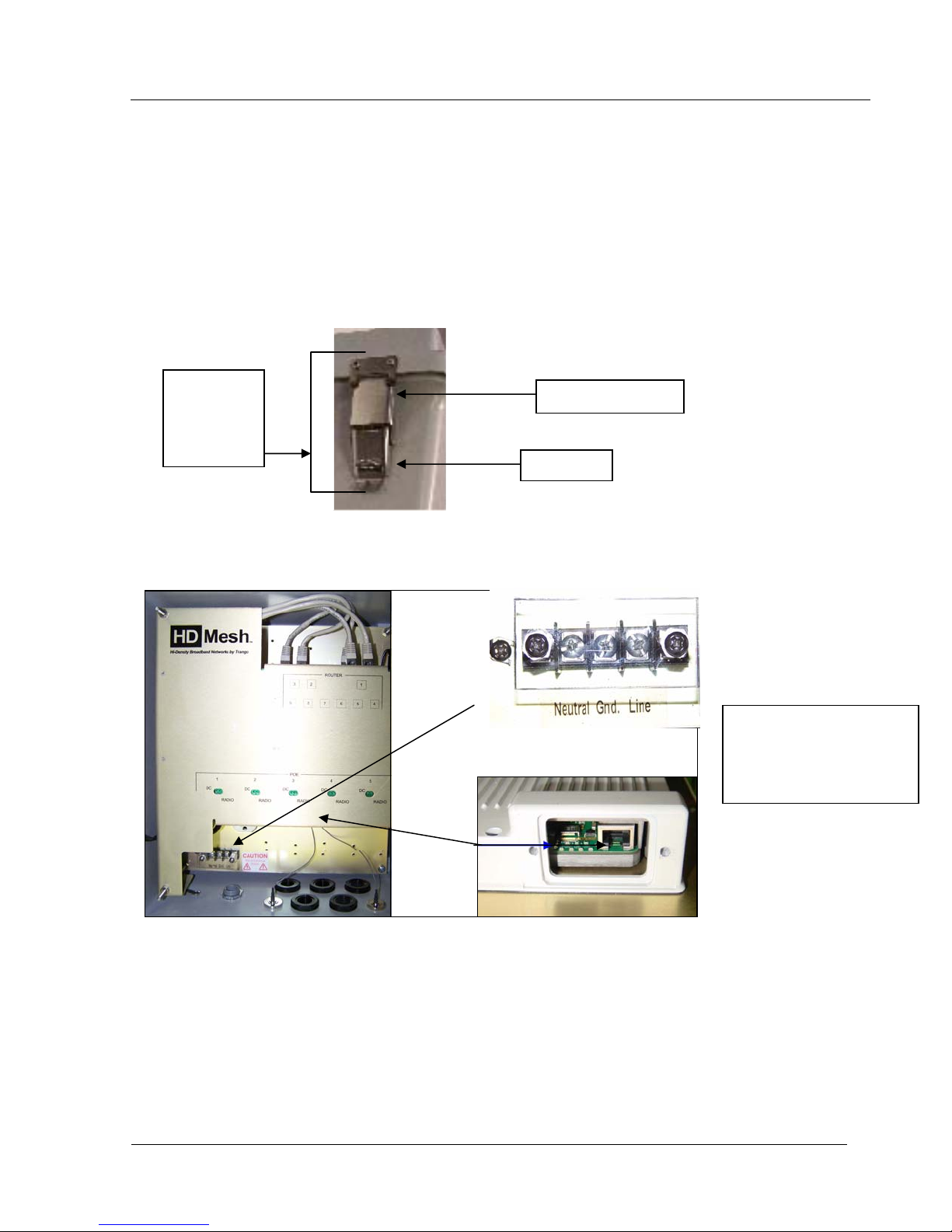
Open the box by flipping up the quick release lockable latches.
Quick
Release
Lockable
Latch
Pull away from box
Flip Up
Connections and Power
Note: Improper wiring of
power may power unit but
may cause damage to
system.
Figure 3
• Power is applied to the HD Mesh unit via the Power Input Terminals located at the bottom left hand
corner inside the box.
• There are 5 PoE ports to provide connection to 5 Trango Broadband radios. Connect a Cat-5 (straight
through) Ethernet cable (Trango Broadband recommends shielded twisted pair) between the POE
port of the HD Mesh unit and the RJ-45 connector on the radio.
• Both green LEDs on the POE of the HD Mesh should be lighted, indicating power is present to the
POE as well as the radio. (Figure 3)
Trango Broadband Wireless — High Density MESH page 7
Page 8
HD Mesh Node
Location of RJ-45/LED Port
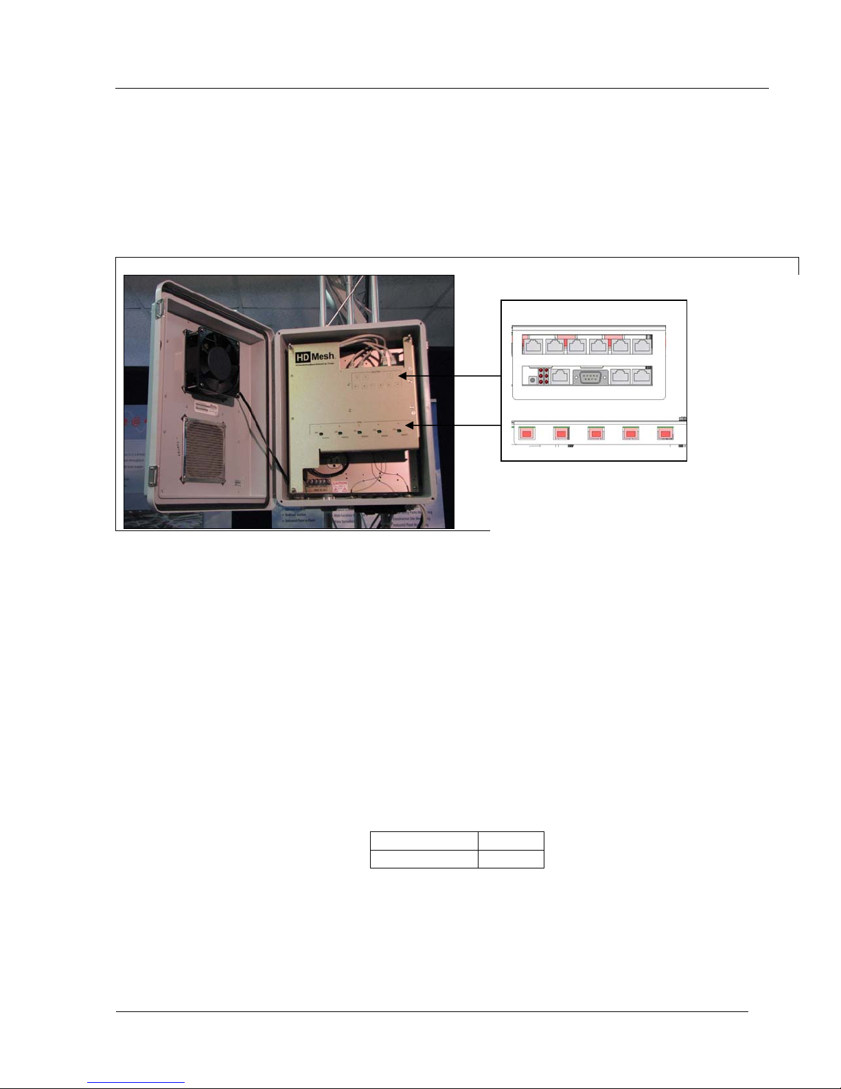
The RJ-45 connectors for Trango Power Over Ethernet (PoE) injectors are located at the bottom of the
mounting plate inside the HD Mesh box. The router ports and serial port are located at the top of the
mounting plate. The PoE diagnostic LEDs are located on the face lid of the mounting plate. Functionality of
the LEDs is described later in this text. (Figure 4)
ROUTER
POE
Figure 4
HD MESH Management
The HD Mesh unit can be configured using a Command Line Interface (CLI), Web Browser (HTTP) interface,
or Winbox (GUI) interface. Although all methods are comprehensive and powerful, the CLI method provides
more functionality.
Password
The HD Mesh unit is pre-configured with the following default account and password. This user name
and password will allow you to gain access via CLI, HTTP, or Winbox.
User Name admin
Password trango
Note: The password will default to a blank password if the unit is set to factory defaults. The user name will still
be admin.
Trango Broadband Wireless — High Density MESH page 8
Page 9
HD Mesh Node
Browser Interface
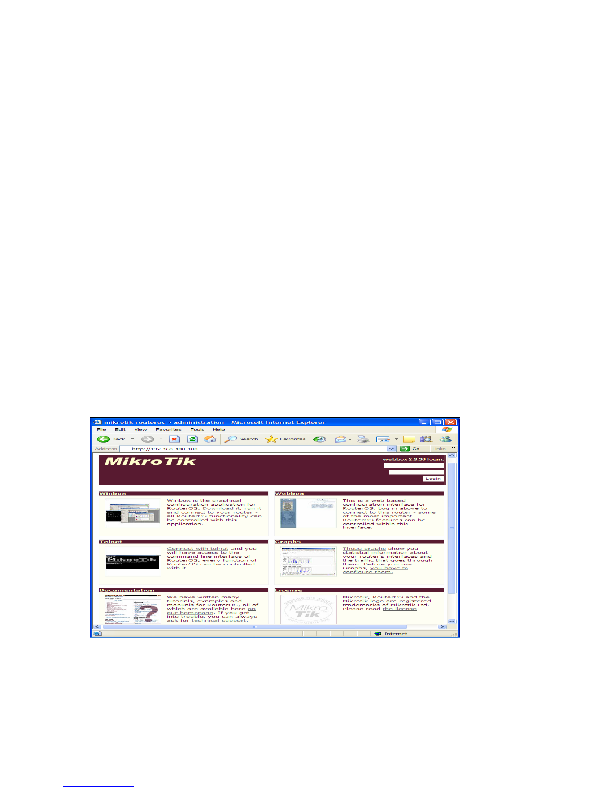
The HDMESH features a convenient and easy-to-use web based configuration and management tool. No
additional software is needed on your computer other than a web browser. The browser interface offers
limited and basic functions, although the majority can only be performed via command line interface (CLI).
To use the browser interface, the following must be present:
• An Ethernet (wired or wireless) connection between a PC and the HD Mesh unit.
• Ethernet PC connection with IP/subnet that is routable to the HD Mesh unit.
• A web browser on the PC (i.e. Microsoft Internet Explorer )
In order to use the browser interface – simply connect the HD Mesh unit to a PC and type the HD Mesh’s IP
address into the web browser (i.e. Microsoft Internet Explorer). This will bring up the Login
page.
Browser Interface Login Screen
The first page of the web browser is called the configuration page. The configuration page offers the
following options.
• Downloading Winbox
• Displaying Graphs
• Telnet into the router
• Documentation from Mikrotik’s Website & License Information
Winbox can be downloaded from the router itself under the configuration page of the web browser.
The top left side of the configuration page offers a link to download the Winbox application. The application
can also be downloaded from Mikrotik’s website. (Figure 5)
Type the username (default: admin) and password (default trango) and continue. This will bring up the
router’s Interface page.
Trango Broadband Wireless — High Density MESH page 9
Figure 5
Page 10

HD Mesh Node
Primary Features and Pages of the Browser Interface:
Navigation Column: Each page features a navigation column that runs along the left-hand side of the page.
On the bottom of the navigation column is the current status of the router including its System ID, IP address,
Time, Date, CPU Utilization, Uptime, Disk Space Free, Disk Space Total, Memory Free, Memory Total, Rx,
Tx, AP, Clients, and Timeout.
The navigation column also features buttons to each of the following pages:
System
period.
Interface
first page shown after login.
Firewall
Protect customer, Protect router, and NAT.
Routes
Simple Queues
PPPoE
Registration Table
Access List
Forward settings.
DHCP Server
Upgrade
Logout
: This page shows ID, Version, System Reset, Reboot, Change password, and Web page refresh
: The interface name, type, IP address, enable/disable and graph are seen on this page. It is the
: This page allows you to setup a basic firewall by selecting the Public interface and check boxes of
: This page will display all routing information with capabilities of adding static routes.
: Simple Queues page allows you to rate limit traffic on the router.
: Allows you to enable PPPoE on an interface and add users and passwords.
: This page will show you current registered clients.
: This page will allow adding an Access List based on MAC address, Interface, Authenticate and
: This page will show you current DHCP server settings to include current DHCP leases.
: This page will allow you to upload an upgrade package or downgrade.
: This link will end the current browser session with the router.
Trango Broadband Wireless — High Density MESH page 10
Page 11
HD Mesh Node
Winbox (GUI) Interface
The HDMESH features a convenient and easy-to-use GUI interface tool. The Winbox interface offers the
closest functionality to the Command Line Interface (CLI). . The Winbox interface provides a lot more
functionality than the Web Interface. Winbox is improving with each release but CLI still provides the most
functionality
To use the Winbox, the following must be present:
• An Ethernet (wired or wireless) connection between a PC and the HD Mesh unit.
• Ethernet PC connection to the HD Mesh unit.
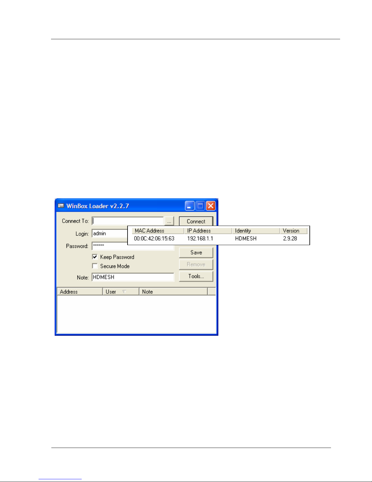
In order to use the Winbox simply connect the HD Mesh unit to a PC and type the HD Mesh’s IP address into
the “Connect To” space. Clicking on the dotted square will perform a broadcast scan and show MAC
addresses and IP addresses of HD Mesh Nodes discovered on the network. Supply a Login Name “admin”
and password “trango” (Figure 6)
Figure 6
Trango Broadband Wireless — High Density MESH page 11
Page 12

HD Mesh Node
Primary Features and Pages of the Winbox Interface:
Menu Bar: Winbox has a menu bar that runs along the left-hand side of the page.
Interface
Wireless
Bridge
PPP
IP
: Includes the following Menus: Addresses, Routers, Pool, ARP, VRRP, Firewall, Socks, UPnP, Traffic
Flow, Accounting, Services, Packing, Neighbors, DNS, DHCP Client, DHCP Server, DHCP Relay, Hotspot,
IPSec, and Proxy.
Routing
.
Ports
Parity, Stop Bits and Flow Control.
Queues
Drivers
System
Logging, History, Console, Scripts, Scheduler, Watchdog, Reboot, Shutdown, NTP Client and NTP Server.
Files
Log
SNMP
Users
Radius
Tools
Traffic monitor, Packet Sniffer, Torch, MAC Server, Graphing, IP Scan, Ping Speed, Flood Ping, and
Netwatch.
New Terminal
Telnet
Password
Certificate
Make SUPOUT.rif
Manual
Exit
: General information of the interface, Status, Ethernet port settings and traffic.
: Wireless status, Access List, Registration, Connect List, Security Profiles, and wireless settings.
: Shows Bridge status, Ports in the Bridge, Filters, Broute, NAT and Hosts.
: Configure PPP interface, Secrets, Profiles, and Active Connections
: Display menus for the following: BGP, RIP, OSPF, and prefix
: Displays the serial port where the following setting can be changed. Name, Baud Rate, Data Bits,
: Display Simple Queues, Interface Queues, Queue Tree, and Queue Types.
: Displays drivers for the Ethernet and Wireless chip set.
: This button shows setting for Identity, Clock, Resources, License, Packages, Auto Upgrade,
: Displays files on your router which include backups and hotspot html pages.
: Display the log information of the router.
: SNMP Server setting. By default public has read only access.
: Displays Users information. By default there is only one account admin which has full access.
: Radius information is displayed and can be configured.
: Tools menu has the following tools: Ping, MAC Ping, Traceroute, Bandwidth Test, BTest Server,
: Opens a CLI session to the router.
: Allows to telnet to an IP address using the following methods of telnet. Telnet, SSH, and MAC Telnet.
: Changes the password of the account that is currently being used.
: This menu allows you to see the current Keys, Import, Decrypt and Reset keys.
: This will prompt for a file name that will be created with troubleshooting information.
: The Manual button is a direct link to Microtik’s manual.
: This will close the Winbox session.
Trango Broadband Wireless — High Density MESH page 12
Page 13

HD Mesh Node
Command Line Interface
The Web browser interface covers very basic features in a limited role. The command line interface
(CLI) provides much more functionality, and is usually the management tool of choice for experienced users.
The CLI can be accessed through Telnet or Console cable.
Telnet
Open a command prompt (DOS) session on your PC. Open a Telnet session by typing:
telnet [ip address of router]
All HD mesh units are pre-configured at the factory. The factory default username is admin and password is
trango. Once you connect to the router you will be greeted with the current RouterOS version information and
prompted for a login.
CLI Login Example
C:>telnet 192.168.100.100
MikroTik v2.9.32
Login: admin
Password:
MMM MMM KKK TTTTTTTTTTT KKK
MMMM MMMM KKK TTTTTTTTTTT KKK
MMM MMMM MMM III KKK KKK RRRRRR OOOOOO TTT III KKK KKK
MMM MM MMM III KKKKK RRR RRR OOO OOO TTT III KKKKK
MMM MMM III KKK KKK RRRRRR OOO OOO TTT III KKK KKK
MMM MMM III KKK KKK RRR RRR OOOOOO TTT III KKK KKK
MikroTik RouterOS 2.9.32 (c) 1999-2006 http://www.mikrotik.com/
Terminal ansi detected, using single line input mode
[admin@HDMESH] > quit
To terminate a CLI session (Telnet or Serial) type the command quit.
Note: Type ? for a listing of CLI commands and directories. More basic information on the CLI will
be covered throughout this text for advance CLI commands reference Mikrotik’s website for
documentation www.mikrotik.com
Trango Broadband Wireless — High Density MESH page 13
Page 14
HD Mesh Node
Section 3 Basic Configuration via Web Browser
This section describes a few basic concepts, as well as how to configure basic settings using the
Browser (HTTP) Interface. This section is written to address only the most basic steps. It is highly
recommended that you visit and read Mikrotik’s website to gain an understanding of all important
configuration parameters.
In this section you will learn the following:
• Configure an IP address
• Configure Firewall
• Configure DHCP Server
• Upgrading the RouterOS
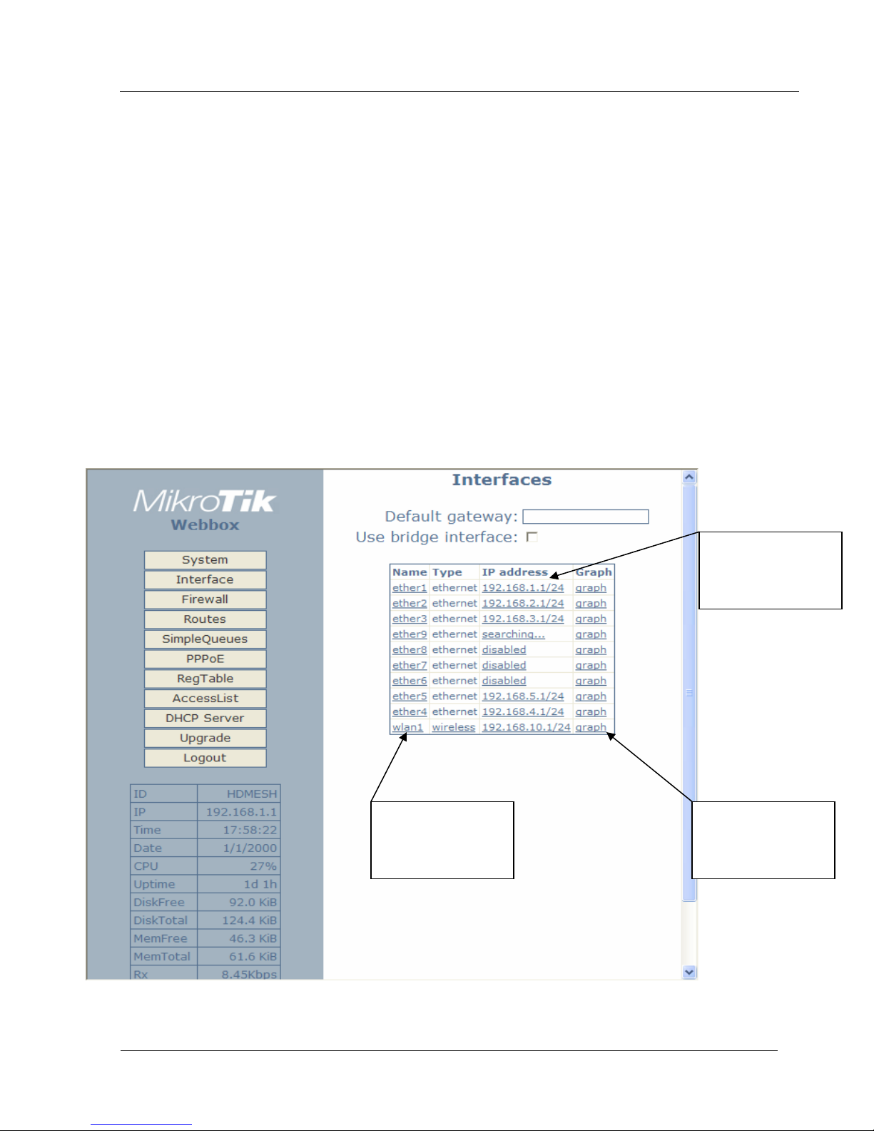
The initial page once you have login is the Interface page. Clicking on the IP address will allow you to
assign the interface an IP address. Clicking on the Interface will allow you to change the interface name from
the standard naming convention. (Figure G)
Web Browser Interface page
Clicking on the
Name will open a
page to change the
Name.
Clicking on the IP
address will bring up
the port
configuration page.
Clicking the graph
link will open a
MRTG graph of the
interface
Figure 7
Trango Broadband Wireless — High Density MESH page 14
Page 15
HD Mesh Node
Port Web Configuration
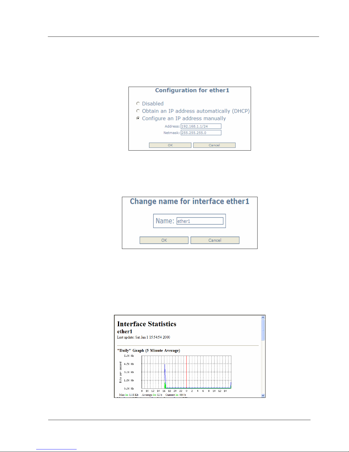
Clicking on the IP address of the interface will bring up the port configuration page. The port can be
disabled, configured to obtain an IP address from a DHCP server, or manually configured with an IP address
and Netmask. (Figure 8)
Figure 8
Port Name Web Configuration
Clicking on the name of the port will allow you to change the name of the port. (Figure 9)
Figure 9
Interface Web Graphing
The Interface page has a graph link which will display the in and out traffic of an interface. The graph
is broken down into daily, weekly, monthly and yearly results. (Figure 10)
Figure 10
Trango Broadband Wireless — High Density MESH page 15
Page 16
HD Mesh Node
System Web Configuration
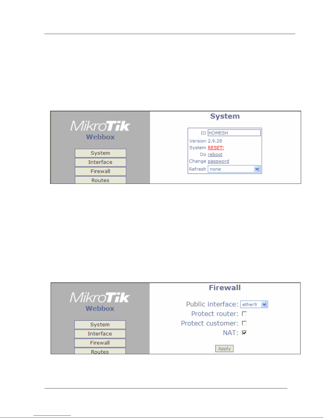
The System page will allow you to change the password simply by clicking the password link. The ID
of the HDMESH can also be changed from the system page. The unit can also be rebooted. The system page
also provides you with a system RESET. (Figure 11)
Note: The system reset defaults the unit completely to Mikrotik’s default configuration. You will then
need to reload Trango’s default configuration.
Figure 11
Firewall Web Configuration
The HD Mesh node by default is configured to use public interface ether 9 and NAT enabled. The
web browser is the easiest way to create a firewall. Simply select a public interface and check the NAT box.
Checking Protect Router and Protect Customer adds additional rules to strength the firewall. (Figure 12)
• Public Interface
• Protect Router
• Protect Customer
• NAT
Figure 12
Trango Broadband Wireless — High Density MESH page 16
Page 17
HD Mesh Node
DHCP Server Web Configuration
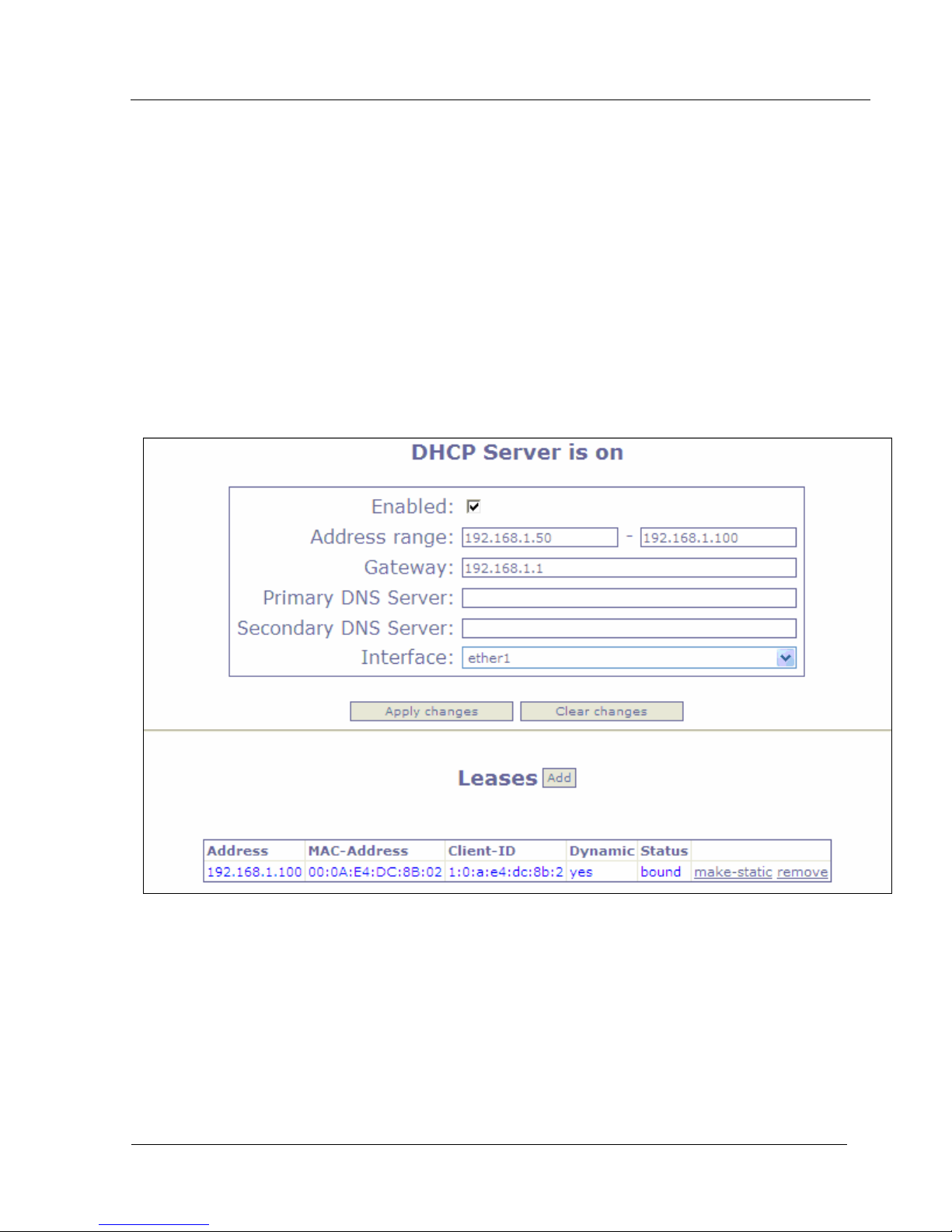
The HD Mesh node is configured by default as a DHCP server. DHCP Services can be applied to any
interface. DHCP leases are also shown on this page. The following information must be to be provided.
(Figure 13)
• The DHCP interface
• The IP address range that will be issues to DHCP clients
• Primary & Secondary DNS Server
• The Gateway IP address
Trango Broadband Wireless — High Density MESH page 17
Figure 13
Page 18
HD Mesh Node
Upgrading RouterOS via Web Browser
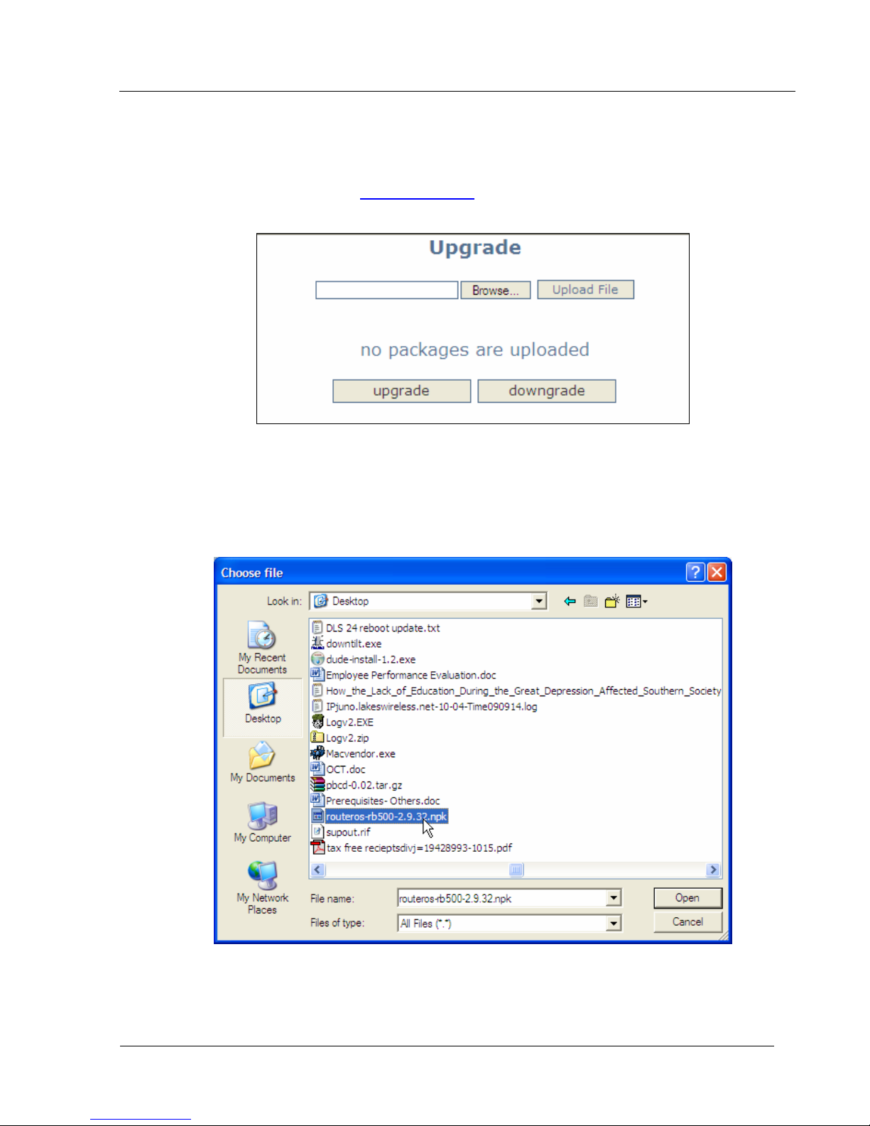
The RouterOS can be upgraded from the web browser upgrade page. The RouterOS can be
downloaded from Mikrotik’s web site www.mikrotik.com
the left side of the web page. (Figure 14)
A window browser will open for you to select the NPK file to upload. Once the file is selected click the upload button
to begin transferring the file from you computer to the router. (Figure 15)
Note: This will only transfer the file to the router
Click on the UPGRADE from the navigation menu on
Figure 14
Trango Broadband Wireless — High Density MESH page 18
Figure 15
Page 19
HD Mesh Node
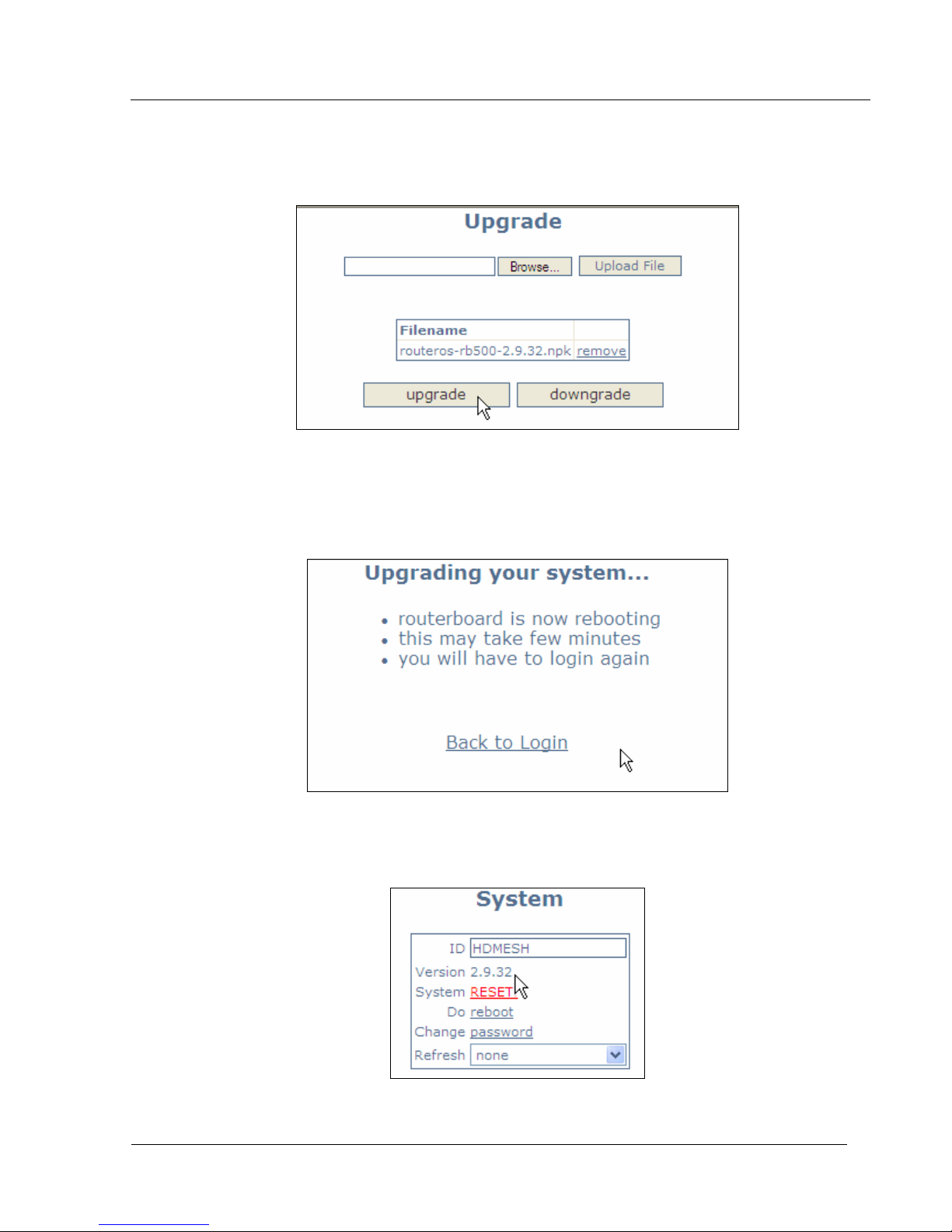
Once the file has been successfully uploaded to the router the upgrade and downgrade button can be used. (Figure
16)
Figure 16
The upgrade procedure will log out the current web session. The process will take a few minutes for the upgrade
procedure to complete. (Figure 17)
Note: DO NOT POWER OFF router during this process
To verify the upgrade procedure was successful. Log back into the router and check the version under the system
page. (Figure 18)
Trango Broadband Wireless — High Density MESH page 19
Figure 17
Figure 18
Page 20
HD Mesh Node
Section 4 Basic Configuration via Winbox
This section describes how to configure basic settings using Winbox. This section is written to
address only the basic steps. It is highly recommended that you visit and read Mikrotik’s website to gain an
understanding of all important configuration parameters.
In this section you will learn the following:
• Configure an IP address
• Configure Wireless Card
• Configure Firewall
• Configure DHCP Server
• Configure OSPF
Configuring an IP address
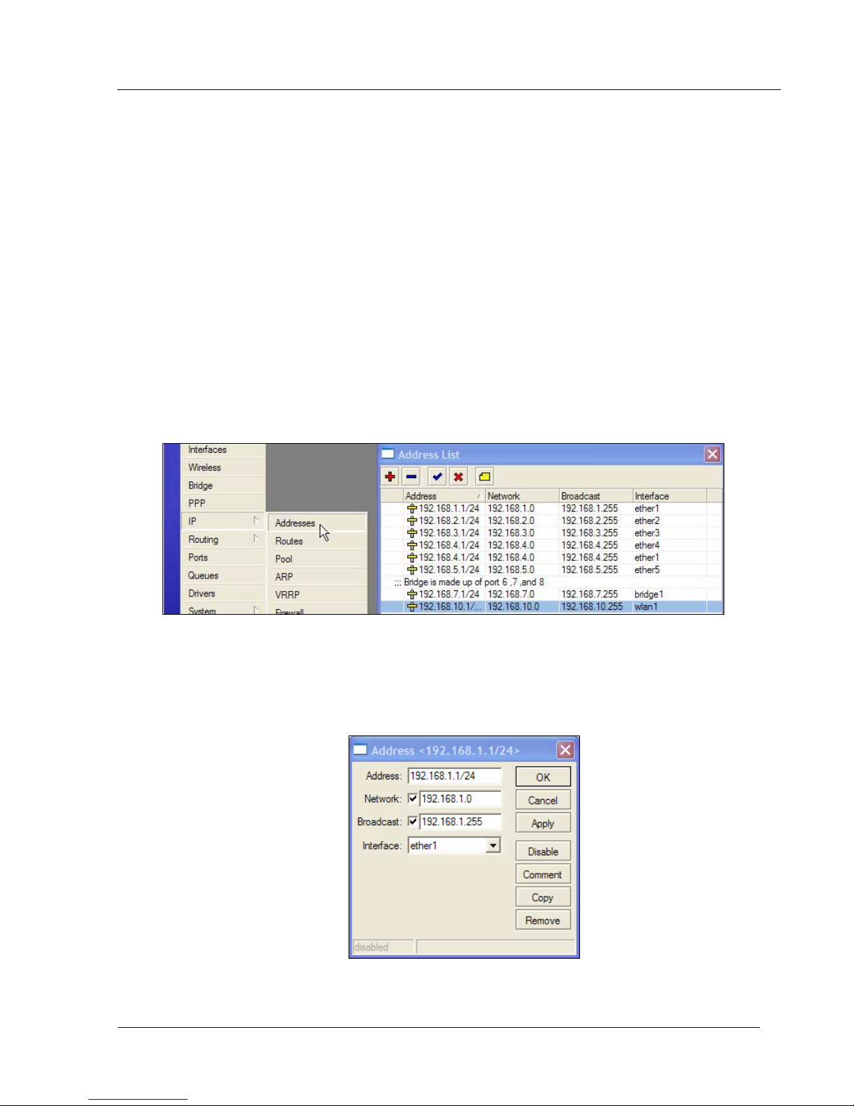
Once you have logged into Winbox the Menu bar on the left will appear. Clicking on the IP and then
addresses will display all interfaces and IP addresses of the interfaces. (Figure 19)
Figure 19
Double clicking on the IP address will bring up the IP address configuration window. Select the
interface; assign an IP address followed by a slash and the bits of the subnet mask. If you provide the bits of
the subnet mask the Network and Broadcast will be populated automatically once apply is clicked. Multiple IP
addresses can be assigned to a single interface. (Figure 20)
Figure 20
Trango Broadband Wireless — High Density MESH page 20
Page 21
HD Mesh Node
Configuring the Wireless Card
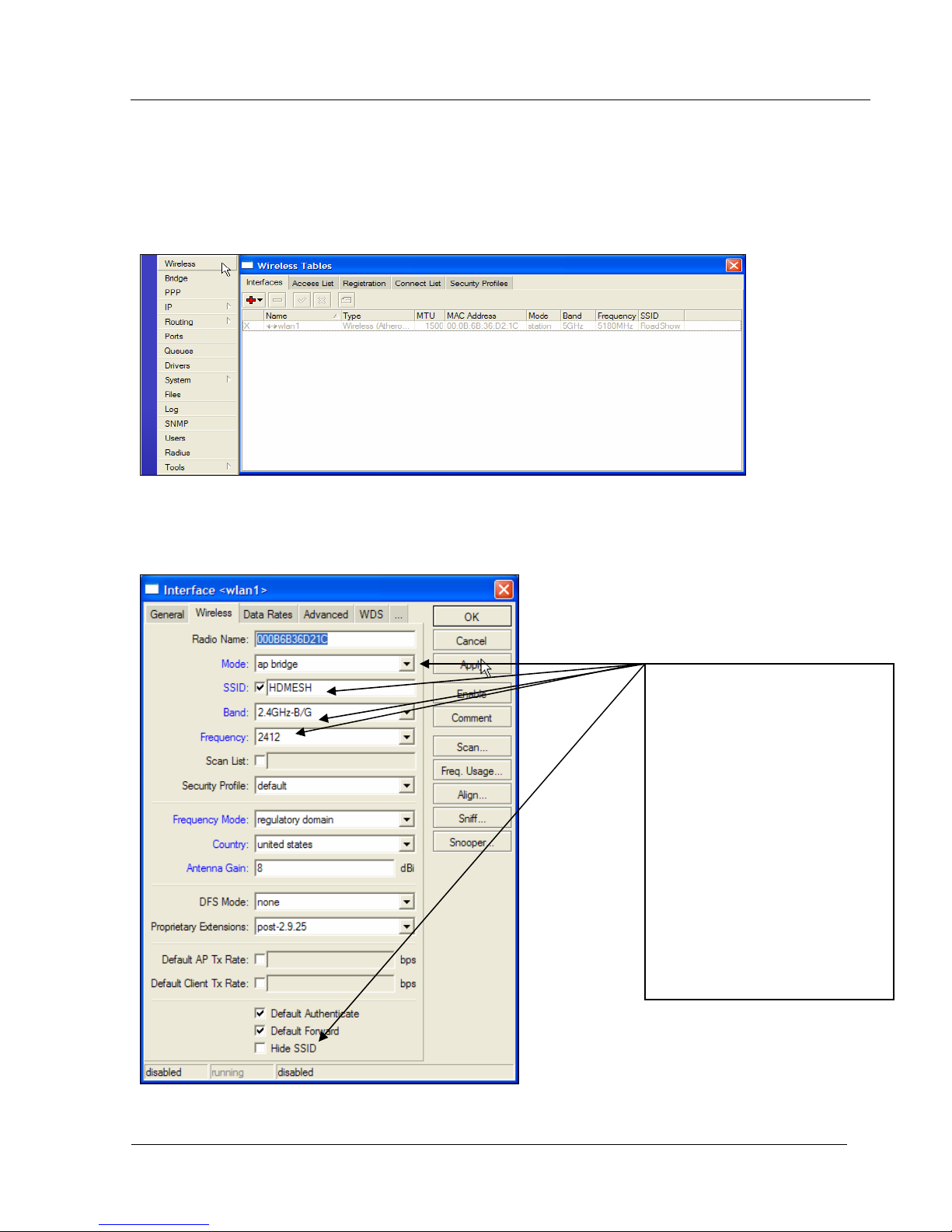
Clicking the Wireless menu option from the menu bar will bring up the Wireless Tables. Double
clicking on the wireless interface will bring up the Interface configuration menu. Once in the configuration
menu there are a number of tabs General, Wireless, Data Rates, Advance and Status are just a few. For
more information on settings consult Mikrotik’s website. (Figure 21 & 22)
Figure 21
.
Figure 22
There are many option that can be
selected in the Wireless tab. The
following are the default setting
configured by Trango Broadband.
Mode: AP Bridge
SSID: HDMESH
Band: 2.4 B/G
Frequency: 2412
Show SSID
Trango Broadband Wireless — High Density MESH page 21
Page 22
HD Mesh Node
Configure Firewall
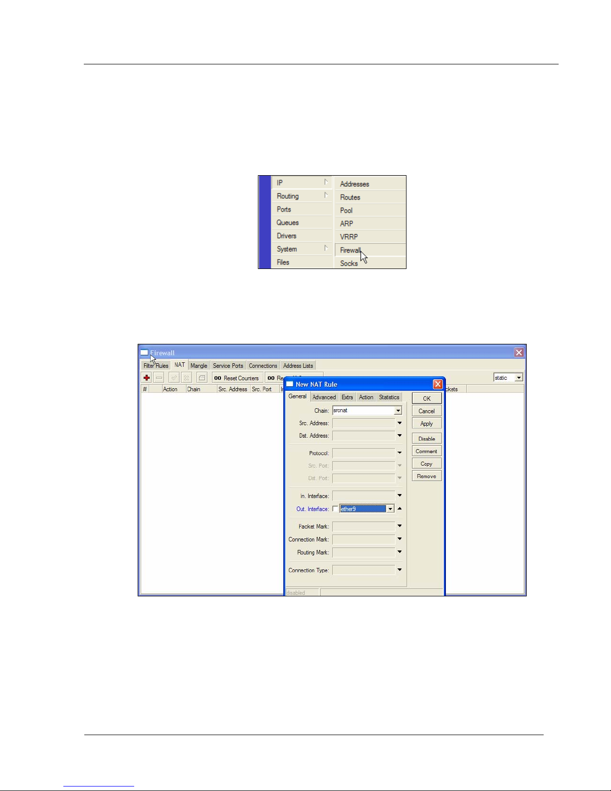
The firewall configuration offers many options but this section will only cover creating NAT on an
interface using masquerading. In the Winbox session select IP menu then Firewall menu option. This will
open the Firewall Windows. (Figure 23)
Figure 23
The following tabs are presented in the firewall window: Filter Rules, NAT, Mangle, Connections, and Address
Lists. Select the NAT table and click on the red plus sign to open the New NAT Rule window.
Once the New NAT Rule window is open the Chain must be set to srcnat and the Out Interface. (Figure 24)
Trango Broadband Wireless — High Density MESH page 22
Figure 24
Page 23
HD Mesh Node
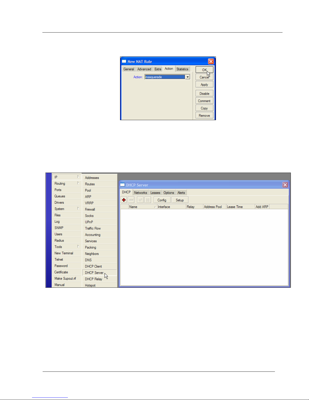
Next in the New NAT Rule select the ACTION tab. The ACTION needs to be set to MASQUERADE.
Click APPLY then OK and the NAT masquerade is configured. (Figure 25)
Figure 25
Configuring DHCP Server
By default the DHCP Server service is enabled in Trango Broadband configuration on Ether1, 2, 3, 4,
5, WLAN, and the bridge interfaces. In order to create a DHCP Server from within Winbox select IP then
DHCP Server. This will open the DHCP Server window (Figure 26)
Trango Broadband Wireless — High Density MESH page 23
Figure 26
Page 24
HD Mesh Node
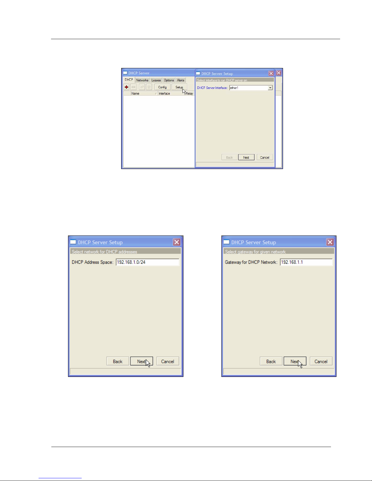
Clicking the Setup button in the DHCP Server window will bring up the DHCP Server Setup window. Select
the interface on which to run DHCP services. (Figure 27)
Figure 27
Once the interface is selected, the DHCP Address Space will need to be added. (Figure 28) This will be
followed by the Gateway for DHCP Network. (Figure 29)
Note The DHCP Gateway is the IP address of the interface.
Note: If not filled out properly the Setup will end without creating the DHCP server
Figure 28 Figure 29
Trango Broadband Wireless — High Density MESH page 24
Page 25
HD Mesh Node
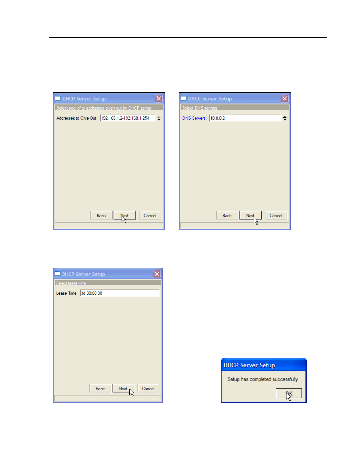
The next prompt will be for the range of IP addresses to give out. This will create an IP pool
automatically. (Figure 30) After the IP address range is given, a DNS server IP address is required. (Figure
31)
Note: If not filled out properly the Setup will end without creating the DHCP server
Figure 30 Figure 31
Lastlly the Lease Time will need to be given. The default is 3 days. The format is days:
hours:minutes:seconds. If this is filled out properly a success windows will open. (Figure 33)
Figure 32 Figure 33
Trango Broadband Wireless — High Density MESH page 25
Page 26
HD Mesh Node
Configuring OSPF
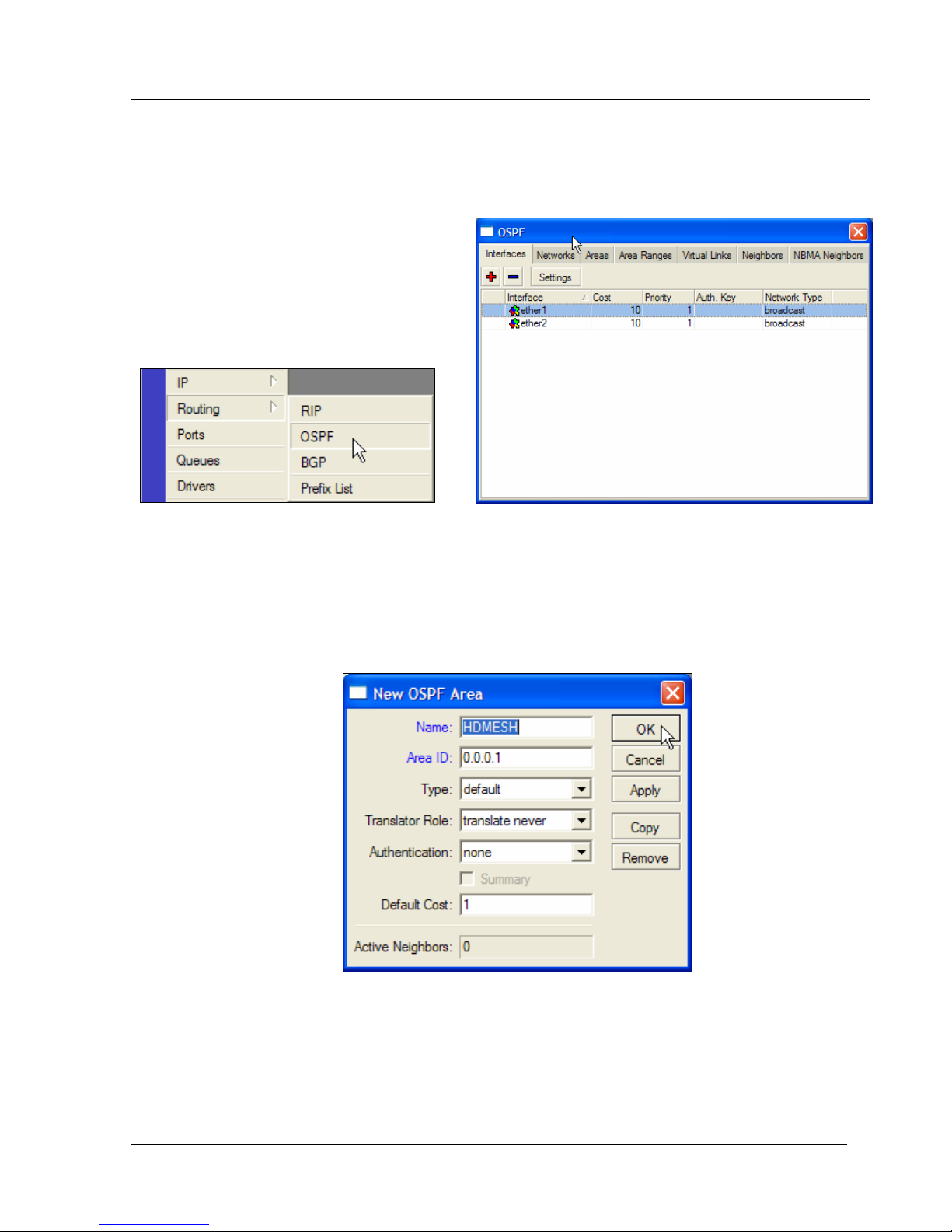
OSPF stands for Open Shortest Path First. This routing protocol is the key to creating redundancy by
the HD Mesh node. This Section will cover how to configure OSPF. The OSPF configuration window can be
opened by selecting Routing then OSPF. (Figures 34 & 35)
Figure 34 Figure 35
Create an area by clicking on the ‘area’ tab and then clicking on the red plus sign. This will open the New
OSPF Area. The following information will need to be supplied. The Area NAME, AREA ID in dotted format.
The rest of the options can remain the same. (Figure 36)
Note: THIS INFORMATION MUST BE THE SAME FOR ALL ROUTERS PARTICAPTING IN THE
MESH
Trango Broadband Wireless — High Density MESH page 26
Figure 36
Page 27
HD Mesh Node
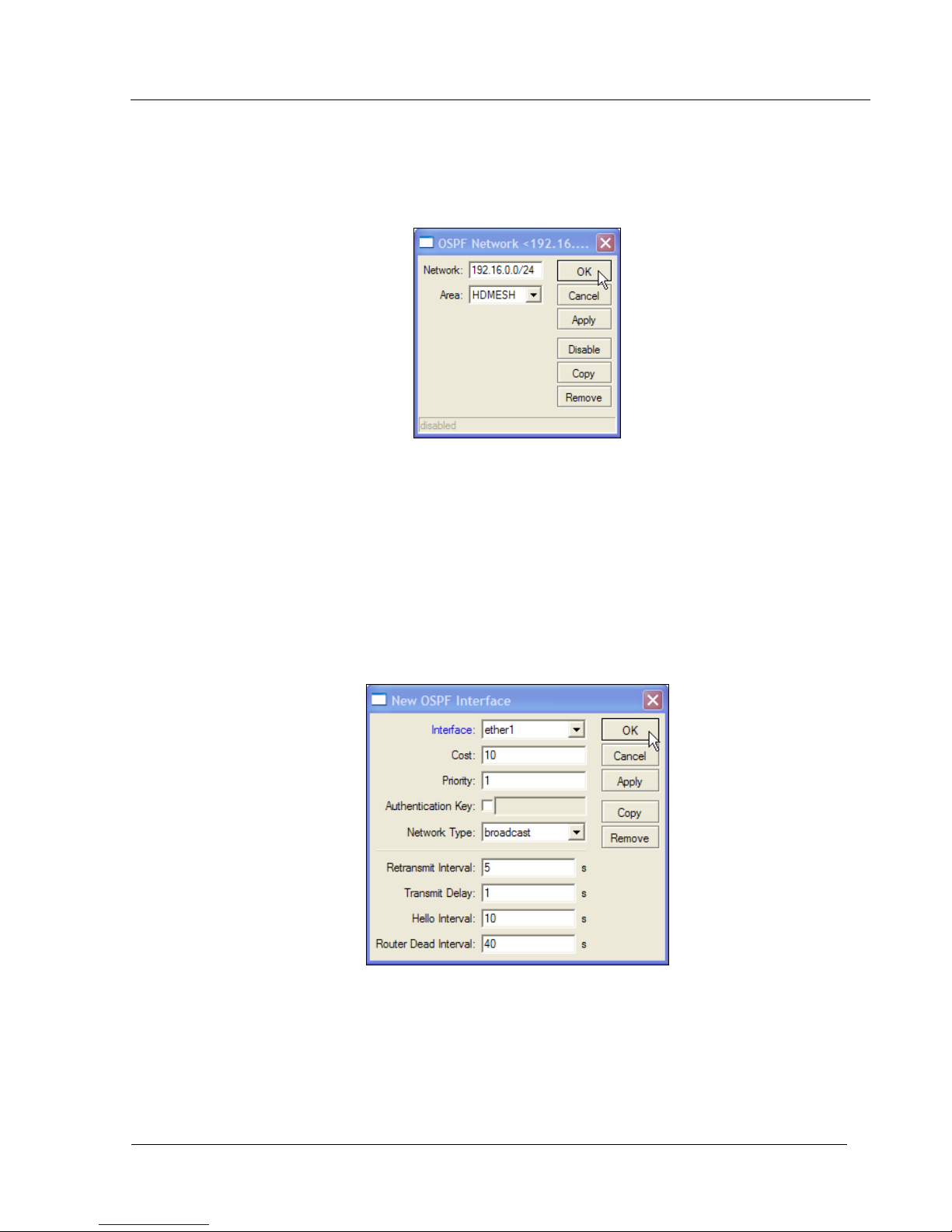
Once the Area is created, the OSPF Networks that will be distributed in the OSPF link need to be
added. In the OSPF window (Figure 35) go to the Network tab and click on the Red Plus sign. This will open
the OSPF network. The Network needs to be added to include the mask. Select the Area which was created.
(Figure 37)
Figure 37
Now that the Area and Network have been added we need to configure which interfaces will pass
OSPF information. In the OSPF window (Figure 35) under the interface tab click on the Red Plus Sign to open
the New OSPF interface window. Select the interface and click APPLY then OK. (Figure 38)
Note: THE FOLLWING SETTING MUST BE THE SAME FOR ALL ROUTERS PARTICAPTING IN
THE MESH
• Retransmit Interval
• Transmit Delay
• Hello Interval
• Router Dead Interval
Trango Broadband Wireless — High Density MESH page 27
Figure 38
Page 28
HD Mesh Node
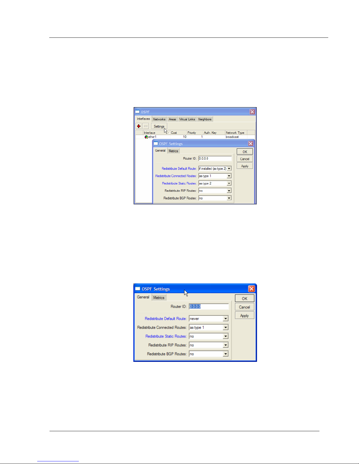
The final step is to configure the OSPF settings. In the Interface tab click on settings to bring up the
OSPF settings windows. The setting will vary depending on the role of the router. If the router has a
connection to the Internet then the following settings are recommended. (Figure 39)
• Redistribute Default Route = if installed (as type 2)
• Redistribute Connected Route = as type 1
• Redistribute Static Routes = as type 2
Figure 39
If your router is just participating in the OSPF then the following OSPF settings are recommended.
(Figure 40)
• Redistribute Default Route = never
• Redistribute Connected Route = as type 1
• Redistribute Static Routes = no
Figure 40
Trango Broadband Wireless — High Density MESH page 28
Page 29

HD Mesh Node
Section 5 Basic Configuration via CLI
This section describes a Command Line Interface configuration. This section is written to address
only the basic steps. It is highly recommended that you visit and read Mikrotik’s website www.mikrotik.com
gain an understanding of all configuration parameters.
In this section you will learn the following:
• Configure an IP address and Gateway
• Configure DHCP client
• Configure DHCP server
Note: See Appendix A for more information on serial port.
The easiest and safest way to configure the router from the CLI is to use the “setup”. This will allow you to
configure the router with simple menu driven options. If an invalid command entered then the setup program
will terminate and no setting will take effect.
Launching CLI “Setup”
[admin@HDMESH] > setup
Setup uses Safe Mode. It means that all changes that are made during setup
are reverted in case of error, or if Ctrl-C is used to abort setup. To keep
changes exit setup using the 'x' key.
[Safe Mode taken]
Choose options by pressing one of the letters in the left column, before
dash. Pressing 'x' will exit current menu, pressing Enter key will select the
entry that is marked by an '*'. You can abort setup at any time by pressing
Ctrl-C.
Entries marked by '+' are already configured.
Entries marked by '-' cannot be used yet.
Entries marked by 'X' cannot be used without installing additional packages.
r - reset all router configuration
+ l - load interface driver
* a - configure ip address and gateway
+ d - setup dhcp client
+ s - setup dhcp server
p - setup pppoe client
t - setup pptp client
x - exit menu
your choice [press Enter to configure ip address and gateway]:
to
Trango Broadband Wireless — High Density MESH page 29
Page 30

HD Mesh Node
Configuring IP Address via CLI Setup
In the setup menu you can configure an IP address simply by supplying the interface name and the IP
address with the netmask.
Example of configuring an IP address
r - reset all router configuration
+ l - load interface driver
+ a - configure ip address and gateway
+ d - setup dhcp client
+ s - setup dhcp server
p - setup pppoe client
t - setup pptp client
* x - exit menu
your choice: a
+ a - add ip address
+ g - setup default gateway
* x - exit menu
your choice: a
enable interface: ether1
ip address/netmask: 192.168.4.1/24
#Enabling interface
/interface enable ether1
#Adding IP address
/ip address add address=192.168.4.1/24 interface=ether1 comment="added by \
setup"
+ a - add ip address
+ g - setup default gateway
* x - exit menu
your choice: x
r - reset all router configuration
+ l - load interface driver
+ a - configure ip address and gateway
+ d - setup dhcp client
+ s - setup dhcp server
p - setup pppoe client
t - setup pptp client
* x - exit menu
your choice: x
[Safe Mode released]
Setup completed successfully.
Following commands were executed during this setup:
#Enabling interface
/interface enable ether1
#Adding IP address
/ip address add address=192.168.4.1/24 interface=ether1 comment="added by \
setup"
[admin@HDMESH] >
Trango Broadband Wireless — High Density MESH page 30
Page 31

HD Mesh Node
Configuring Gateway via CLI Setup
Simply selecting an option will bring the next menu prompt. The only information needed to set the Gateway
is the gateway IP address.
Example of configuring the Gateway on the router
your choice [press Enter to configure ip address and gateway]: a
+ a - add ip address
* g - setup default gateway
x - exit menu
your choice [press Enter to setup default gateway]: g
gateway: 192.168.4.254
#Adding default route
/ip route add dst-address=0.0.0.0/0 gateway=192.168.4.254 comment="added by \
setup"
+ a - add ip address
+ g - setup default gateway
* x - exit menu
your choice: x
r - reset all router configuration
+ l - load interface driver
+ a - configure ip address and gateway
+ d - setup dhcp client
+ s - setup dhcp server
p - setup pppoe client
t - setup pptp client
* x - exit menu
your choice: x
Configure DHCP Client via CLI Setup
Follow the menu options and supply the interface which is to be configured as a DHCP client.
r - reset all router configuration
+ l - load interface driver
+ a - configure ip address and gateway
+ d - setup dhcp client
+ s - setup dhcp server
p - setup pppoe client
t - setup pptp client
* x - exit menu
your choice: d
interface: ether8
#Adding DHCP client
/ip dhcp-client add disabled=no interface=ether8 comment="added by setup"
r - reset all router configuration
+ l - load interface driver
+ a - configure ip address and gateway
+ d - setup dhcp client
+ s - setup dhcp server
p - setup pppoe client
t - setup pptp client
* x - exit menu
your choice: x
Trango Broadband Wireless — High Density MESH page 31
Page 32

HD Mesh Node
Configuring DHCP Server via CLI Setup
Following the menu option the following information will need to be provided in order to create the
DHCP Server
• DHCP server interface:
• DHCP address space:
• gateway for DHCP network:
• DHCP relay
• addresses to give out:
• DNS servers:
• lease time:
Example of a configured DHCP server.
+ s - setup dhcp server
p - setup pppoe client
t - setup pptp client
* x - exit menu
your choice: s
dhcp server interface: ether6
dhcp address space: 192.168.0.0/24
gateway for dhcp network: 0.0.0.1
dhcp relay: 0.0.0.0
addresses to give out: 0.0.0.2-255.255.255.254
dns servers: 192.168.1.1,10.8.0.2
lease time: 3d
#Adding DHCP server IP address pool
/ip pool add name=dhcp-pool-1 ranges=0.0.0.2-255.255.255.254
#Adding DHCP network
/ip dhcp-server network add address=192.168.0.0/24 \
dns-server=192.168.1.1,10.8.0.2 gateway=0.0.0.1 comment="added by setup"
#Adding DHCP server
/ip dhcp-server add interface=ether6 address-pool=dhcp-pool-1 \
lease-time=3d00:00:00 disabled=no
r - reset all router configuration
+ l - load interface driver
+ a - configure ip address and gateway
+ d - setup dhcp client
+ s - setup dhcp server
p - setup pppoe client
t - setup pptp client
* x - exit menu
your choice: x
[Safe Mode released]
Setup completed successfully.
[admin@HDMESH] >
Trango Broadband Wireless — High Density MESH page 32
Page 33
HD Mesh Node
Section 6 Default Configuration
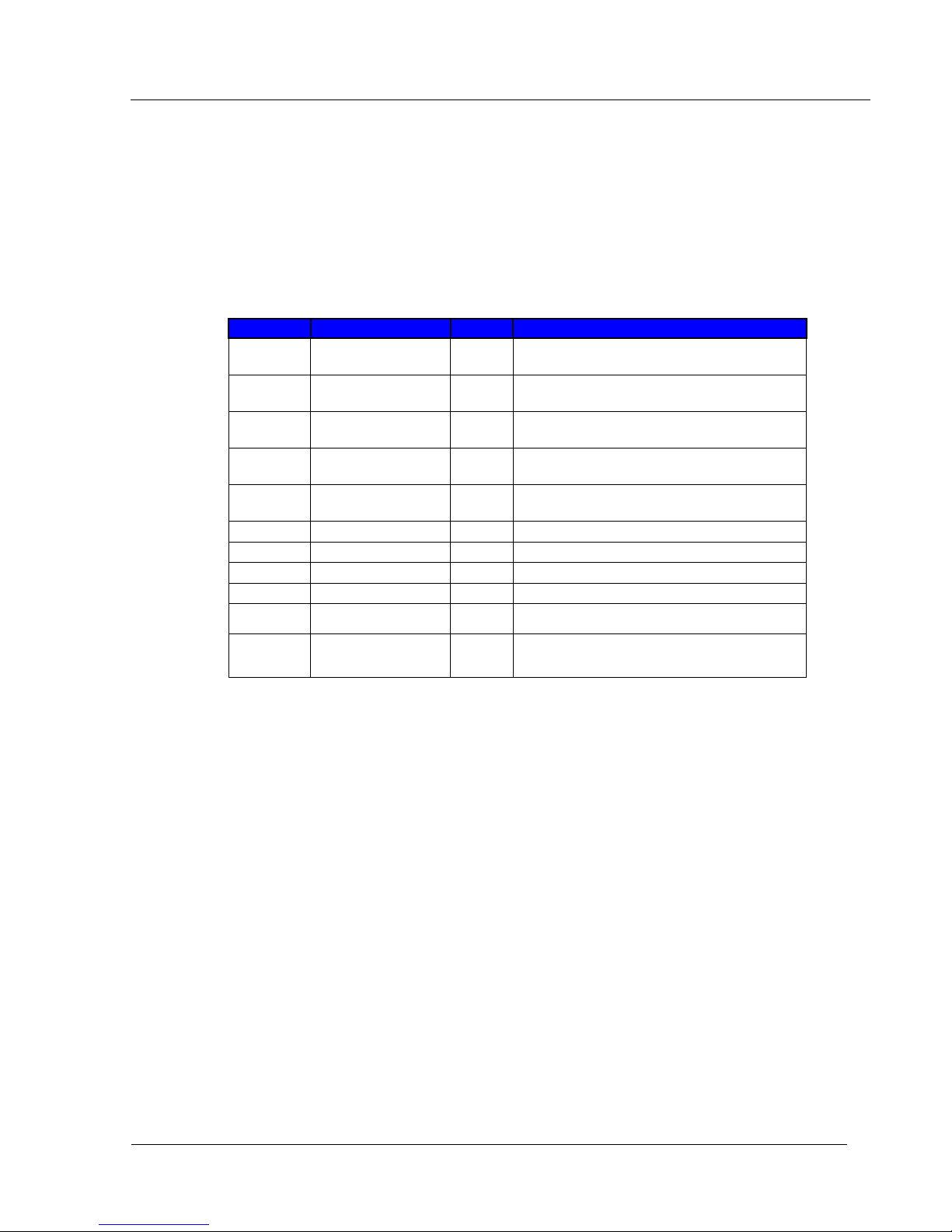
The HD Mesh node is configured with the first 5 ports as router ports, each with their own IP address.
The ports are also configured to give out DHCP IP addresses. Ports 6, 7, and 8 are configured to act as a
single bridge. The bridge is configured with an IP Address and also as a DHCP server. The wireless card is
configured with its own IP address and also as a DHCP Server. Port 9 is configured as a DHCP client. (Figure
41)
Port IP address Bridge Comments
DHCP Server issues IP addresses from
Ether 1 192.168.1.1/24 No
Ether 2 192.168.2.1/24 No
Ether 3 192.168.3.1/24 No
Ether 4 192.168.4.1/24 No
Ether 5 192.168.5.1/24 No
Ether 6 N/A Yes Bridge port 1
Ether 7 N/A Yes Bridge port 1
Ether 8 N/A Yes Bridge port 1
Ether 9 No DHCP Client- NAT
DHCP range 192.168.1.50-100
DHCP Server issues IP addresses from
DHCP range 192.168.2.50-100
DHCP Server issues IP addresses from
DHCP range 192.168.3.50-100
DHCP Server issues IP addresses from
DHCP range 192.168.4.50-100
DHCP Server issues IP addresses from
DHCP range 192.168.5.50-100
WLAN 1 192.168.1.10/24 No 802.11b/g SSID: HDMESH
DHCP Server issues IP addresses from
Bridge 1 192.168.7.1/24
DHCP range 192.168.7.50-100
Figure 41
Trango Broadband Wireless — High Density MESH page 33
Page 34
HD Mesh Node
Restoring Default Configuration WinBox
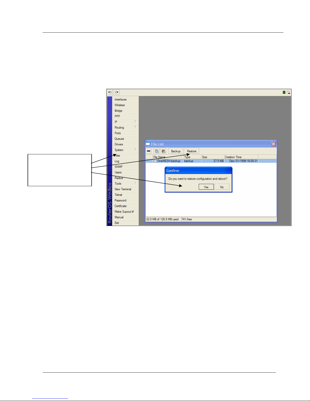
Each router has a backup of this configuration stored in its file system. The backup file can be
seen through Winbox by selecting files. The name of the backup file is “OneMESH.backup”. Select this file
and click on Restore and the unit will prompt you to restore and reboot.
Click on File, Select the
backup file and Click on
Restore. You will be
prompted to confirm
Figure 42
Trango Broadband Wireless — High Density MESH page 34
Page 35

HD Mesh Node
Restoring Default Configuration Command Line Interface
The default configuration can also be reloaded via the command line. Simply login to the Mikrotik
router and type the following command. System backup load name=OneMESH
Example of loading default configuration.
MikroTik v2.9.32
Login: admin
Password:
MMM MMM KKK TTTTTTTTTTT KKK
MMMM MMMM KKK TTTTTTTTTTT KKK
MMM MMMM MMM III KKK KKK RRRRRR OOOOOO TTT III KKK KKK
MMM MM MMM III KKKKK RRR RRR OOO OOO TTT III KKKKK
MMM MMM III KKK KKK RRRRRR OOO OOO TTT III KKK KKK
MMM MMM III KKK KKK RRR RRR OOOOOO TTT III KKK KKK
MikroTik RouterOS 2.9.32 (c) 1999-2006 http://www.mikrotik.com/
Terminal ansi detected, using single line input mode
[admin@HDMESH] >
[admin@HDMESH] > system backup load name=OneMESH
Restore and reboot? [y/N]: y
Restoring system configuration
System configuration restored, rebooting now
[admin@HDMESH] system backup>
Trango Broadband Wireless — High Density MESH page 35
Page 36
HD Mesh Node
Appendix A Serial Port
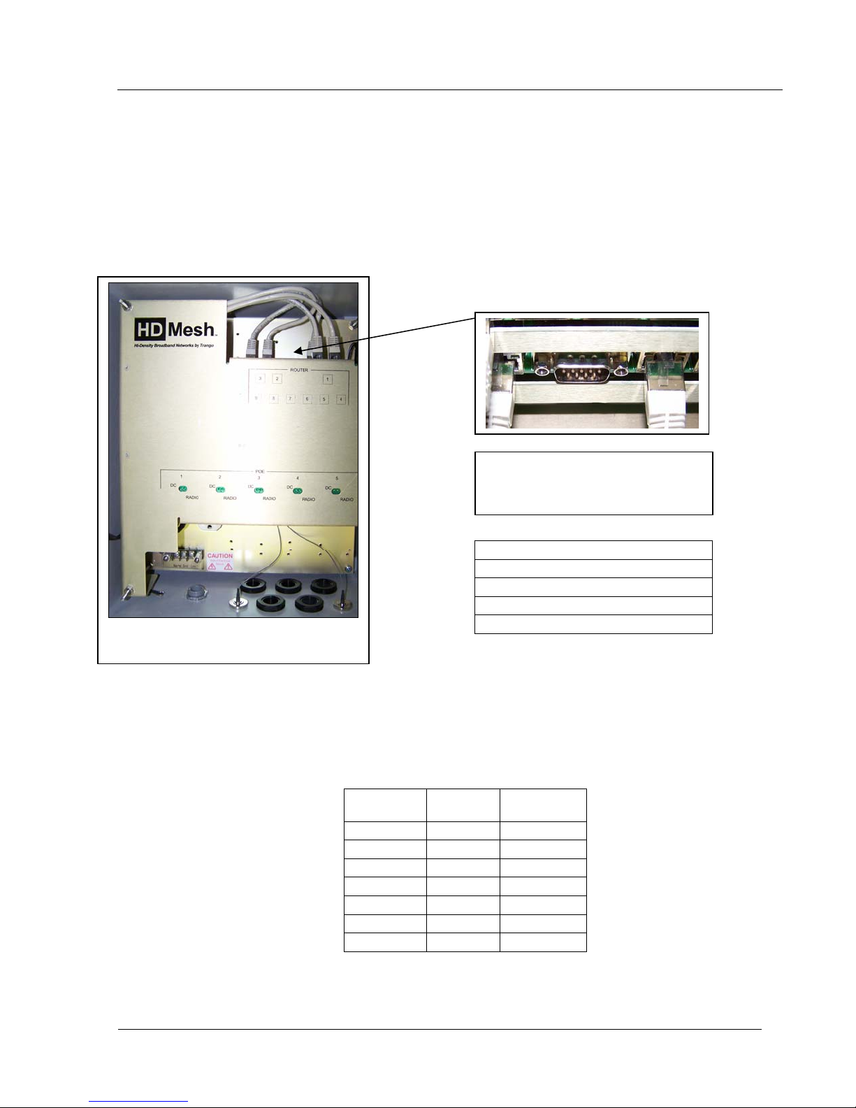
The HD Mesh unit features a serial port. The serial port is useful in the event that the router cannot
be accessed via TCP/IP (HTTP, Telnet, or Winbox). A Terminal Emulation program (such as HyperTerminal
on the Windows operating system) can be used to access the HD Mesh’s CLI using the serial port, which is
located in the top right side of the enclosure. The serial 9 pin db female connector can be used with a
standard null-modem cable to manage the HD Mesh unit.
Figure 43
The settings below are needed to gain
access to the HD Mesh unit via the
console cable.
115200bit/s
8 data bits
1 stop bit
no parity
Hardware RTS/CTS
Management serial cable
The console cable needs to be a 9 pin db female to 9 pin db female connector cable. A null modem
cable can be used to manage the HD Mesh unit. You can also use the pin outs below to manufacture your
own serial cable.
Trango Broadband Wireless — High Density MESH page 36
DB9
Female
1 + 6 CD+DSR 4
2 RxD 3
3 TxD 2
4 DTR 1 + 6
5 GND 5
7 RTS 8
8 CTS 7
Function
Figure 44
DB 9
Female
Page 37

HD Mesh Node
Appendix B Specifications
All specifications apply to HD Mesh Node
HD Mesh Node Enclosure
HD Mesh Box
Ratings
Dimensions
Weight
Router board
PoE board
Omni 8 dBi antenna
Mounting hardware
kit
N Male connectors
Cat-5 Strain relief
connectors
NEMA rated outdoor enclosure
NEMA 3R / IP42
14 in. × 12 in. × 7 in. (39.3 × 34.2 × 19.5 cm)
17 lbs (8 Kg)
9 Ethernet ports, configurable to either router or bridge ports
5 PoE Ports, proprietary for Trango units only
N-type female connector,
360° coverage
2 U-bolts (4 nuts), 2 mounting
brackets, 1 screw kit (4 screws,
4 nuts, 4 washers)
2 N-type connector caps
6 to 12 mm
Input voltage
Power consumption
Serial port
Expansion slots
Temp range
Trango Broadband Wireless — High Density MESH page 37
6 MiniPCI Slots (two can be use for two WiFi APs)
90-120 VAC or 210 - 230 VAC*
350 Watts maximum*
Router
9 Auto-sensing ports (10/100/1000 Mbps),
configurable to either router or bridge ports Ethernet ports
DB-9 (RS-232C), standard male DB9
asynchronous serial Port
64 MB NAND memory chip,
CompactFlash type I/II slot Onboard memory
†
-40° F to 140° F (-40° C to 60° C)
Page 38

HD Mesh Node
Wireless Board
802.11a: -88 dBm @ 6 Mbps, -71 dBm @ 54 Mbps
Sensitivity
Modulation
techniques
64-QAM
RF power output
Wi-FiR
802.11b: -95 dBm @ 1 Mbps, -90 dBm @ 11 Mbps
802.11g: -90 dBm @ 6 Mbps, -74 dBm @ 54 Mbps
Hardware 40 bit & 108 bit WEP.
Hardware AES-CCM Security
802.11b/g: DSSS (DBSP, DQPSK, CCK) OFDM
for data rate > 20 Mbps
802.11a: OFDM (BPSK, QPSK, 10-QAM,
18 dBm @ 2.4 GHz
17 dBm @ 5.8 GHz
WECA Compliant, FCC Part 15 (USA)
* The system will use a maximum of 350 Watts. However, if any of the other 3 outlets are in use, the
consumption will increase by the device’s power consumption.
†
Fan turns ON at 120° F (49° C) and OFF at 90° F (32° C).
Heat plate turns ON at -40° F (-40° C) and OFF at 60° F (15° C).
Trango Broadband Wireless — High Density MESH page 38
 Loading...