

Page 1
▲
WARNING
!
▲
WARNING
!
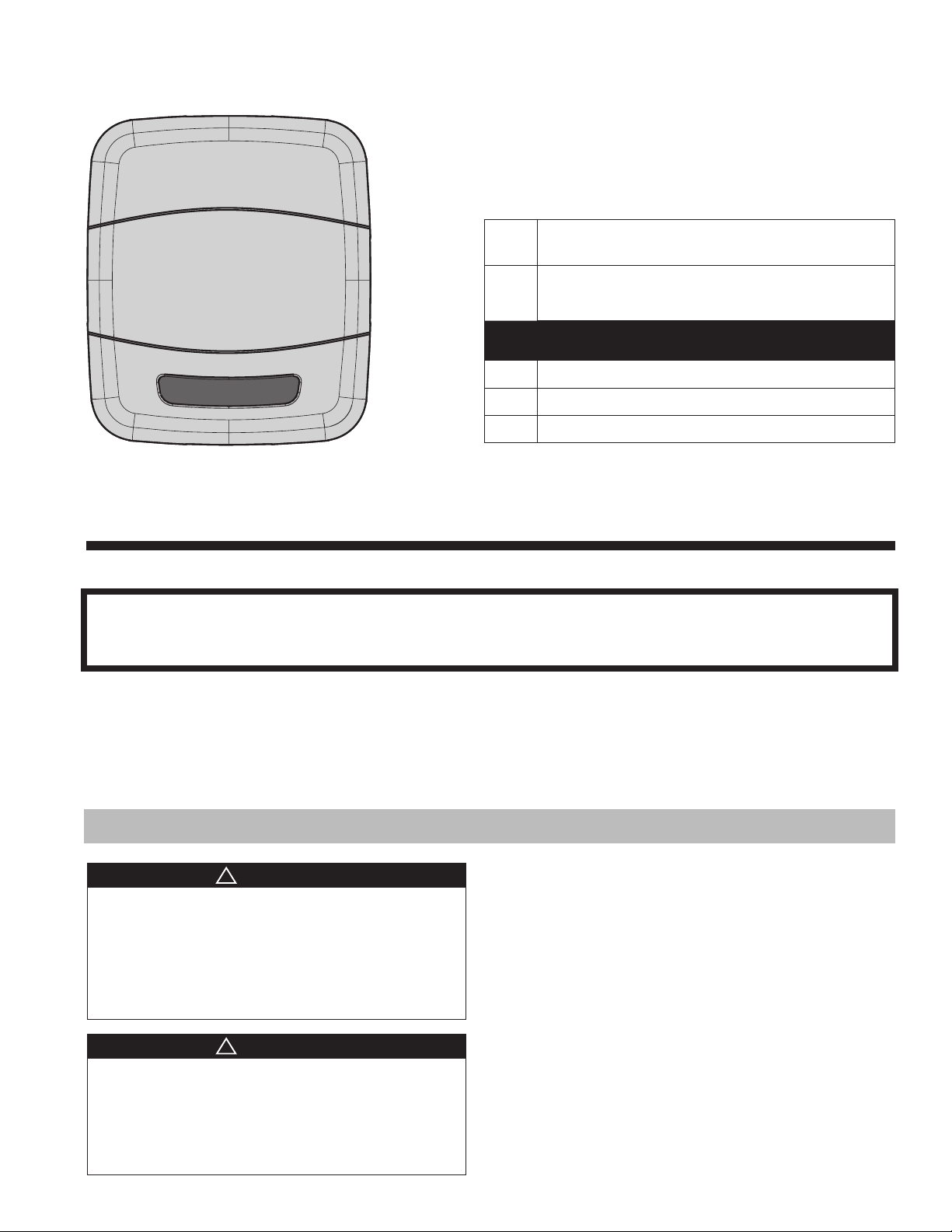
Zone Panel
ZZONEPNLAC52ZB (Kit)
ZZONEEXPAC52ZB (Zone Panel)
18-HD66D1-4
Installation Guide
Other Installation Guides may be necessary, based on system configuration.
A complete list of other optional components is shown below.
Control (required) *ZONE950AC52ZA or
1
*ZON1050AC52ZA
Relay Panel
2
For use with 24V indoor systems (optional)
3 Zone Panel
Zone Sensor with Display (optional)
4
Zone Sensor (optional)
5
Zone Dampers (optional)
6
ALL phases of this installation must comply with NATIONAL, STATE AND LOCAL CODES
IMPORTANT — Proper application is critical when installing zoning systems. Not done correctly, the HVAC
and zoning systems will not provide the expected comfort. Reference application bulletins CNT-APG003EN/Trane and CNT-APG004-EN/AS for detailed information on Zoning Application
IMPORTANT — This Document is customer property and is to remain with this unit. Please return to service information pack upon completion of work.
These instructions do not cover all variations in systems or provide for every possible contingency to be met in connection with
the installation. Should further information be desired or should particular problems arise which are not covered sufficiently for the
purchaser’s purposes, the matter should be referred to your installing dealer or local distributor.
Section 1. Safety
Table of Contents
This information is intended for use by individuals possessing adequate backgrounds of electrical and mechanical
experience. Any attempt to repair a central air conditioning
product may result in personal injury and/or property damage. The manufacture or seller cannot be responsible for
the interpretation of this information, nor can it assume any
liability in connection with its use.
LIVE ELECTRICAL COMPONENTS!
During installation, testing, servicing, and troubleshooting of this product, it may be necessary to work with live
electrical components. Failure to follow all electrical safety
precautions when exposed to live electrical components
could result in death or serious injury.
Section 1. Safety ................................................1
Section 2. General Information .......................... 2
Section 3. Installation ......................................... 6
Section 4. Zoning Setup .................................. 16
Section 5. Zone Sensor Setup ......................... 22
Section 6. Damper Test Mode ..........................24
Section 7. User Interface .................................25
Section 8. Control Board Test Points ............... 26
Section 9. Troubleshooting ...............................28
10/17
Page 2
Section 2. General Information
1
2
4
3
5
10
11
6
8
9
7
ZONES
1 - 4
5 - 8
ByPass
Zone Dampers
Sensors
C
ommon
PO/Open
PC/Clos
e
Static Press
Gnd/Grn
S
ignal/Blk
+5
V/Red
Temper
atureRemote Indoor
Disch
ar
ge Air
Dischar
ge Air
Return A
i
r
R
e
tu
rn
Air
Mix
ed
Air
Mixed Air
Zo
ne 1
or 5
Zone
1 or 5
Zone 2
or 6
Zon
e
2
o
r 6
Zone
3 or 7
Z
one
3 or 7
Z
one
4
or 8
Zone 4 or 8
Zone
1 or 5
Ind
oor/
Relay P
anel
Ou
tdoor
Zone Panel
(Zones 5-8)
24V
Tran
s
.
Co
mmon
PO/Open
PC/Clo
s
e
Zone
2 or 6
C
ommon
PO/
Ope
n
PC/Clo
s
e
Zone
3 or 7
Common
PO/Ope
n
PC/Close
Zone
4 or 8
Common
PO/Ope
n
PC/
Close
Comm
R
BD B
B
R
BD
D
Zone Panel
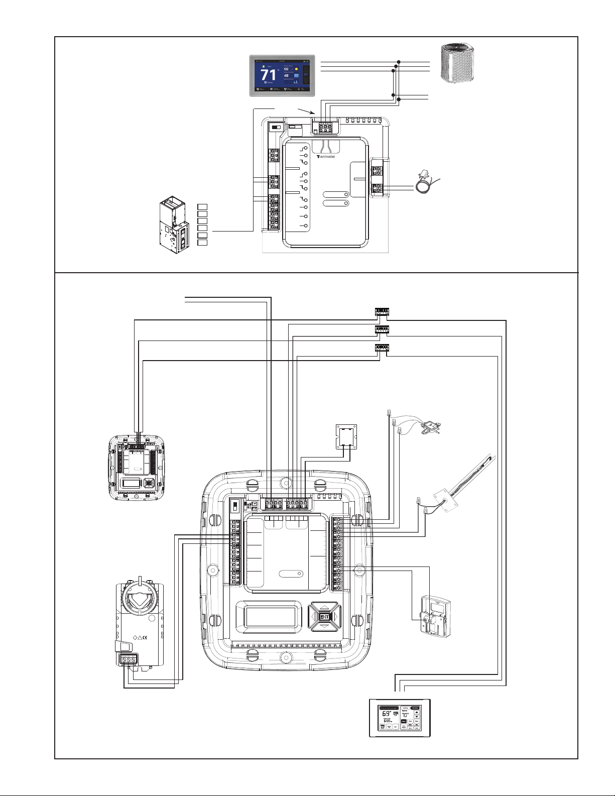
2.1 Overview
The Zone Panel is a wall mounted low voltage panel that enables the control to connect to and manage
zoning components.
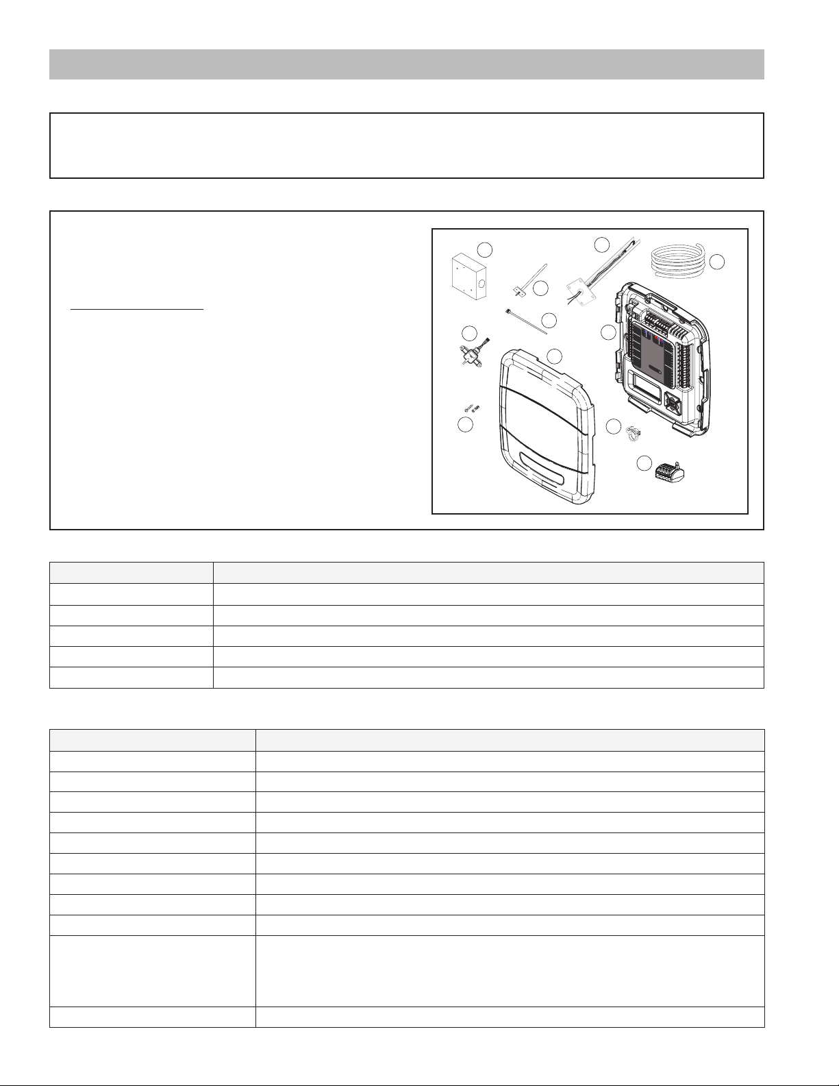
2.2 Contents in Zone Panel Kit (ZZONEPNLAC52ZB)
Open and inspect contents for damaged or missing
items. Each kit will contain:
Item Qty Description
1 1 Zone Panel cover
2 1 Zone Panel base
3 1 Discharge Air Temperature Sensor
4 1 Static Pressure Transducer
5 1 Transducer Enclosure
6 2 Static Pressure Probe
7 1 Clear Flexible Tubing (8 ft.)
8 4 Mounting screws/anchors
9 4 Wire Ties
10 4 Tubing Clamps
11 3 Clamp-style Connectors
12 1 Installer’s Guide (not pictured)
2.3 Optional Accessories
Product Model Description
*ZONE940AC52ZA Communicating Zone Sensor with Display
ZZSENSAL0400AA Non-Communicating Zone Sensor
SEN 00462 Return Air/Mixed Air Sensor
ZZONEEXPAC52ZB Additional Zone Panel for zones 5-8
120/240VAC Transformer
Field-Supplied, sizing dependent on VA requirements of Zone Panel and installed components
2.4 Specifications
Specification Description
Product Model: ZZONEEXPAC52ZB
Product: Zone Panel
Size: 8.0” width x 9.3” height x 1.9” depth
Storage Temperature: -40° to 175°F, 5% to 95% RH non-condensing
Operating Temperature: -40° to 150°F, 5% to 95% RH non-condensing
Input Power: 24 VAC from external transformer (Range: 18-32 VAC)
Power Consumption: 2 VA for each Zone Panel (damper VA not included)
Wire usage: Minimum 18 gauge NEC approved control wiring
HVAC System Type Compatible: Standard (gas/oil/electric/hydronic), Heat Pump, Dual Fuel
Multistage System Compatible: Standard HVAC Systems: Up to 3 stages of heating and 2 stages of cooling (including
Communications: ~12 VDC
2 18-HD66D1-4
modulating heating)
Heat Pump Systems: Up to 5 stages of heating (2 compressor, 3 aux heat—including
modulating heating) and 2 stages of cooling
Page 3
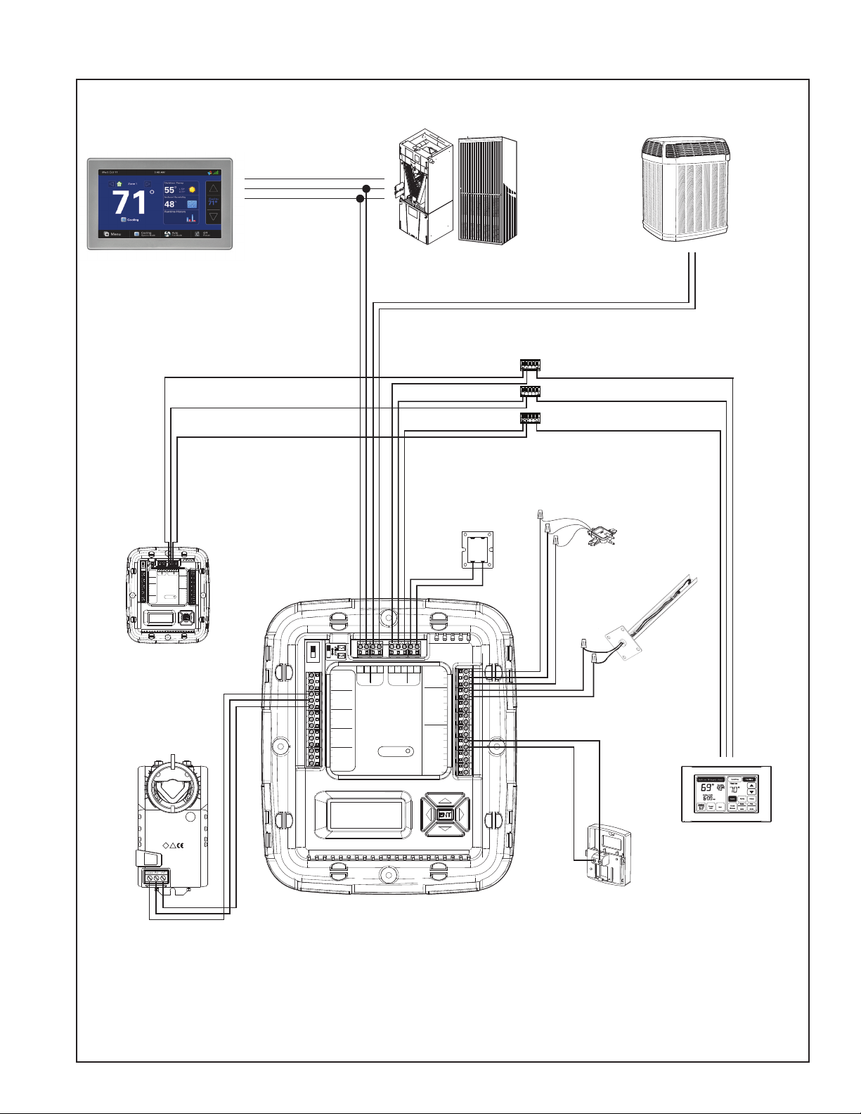
2.4 System Connections
PCPOCOM
Communicating
Communicating Indoor Unit
Communicating Outdoor Unit
Control
R
B
D
R
B
D
Communicating
Indoor Unit
Communicating
Outdoor Unit
BDD
Clamp-style Connectors
R
B
Static Pressure
Field-Supplied 24V
Transformer
TRANS.
1 - 4
1 - 4
ZONES
ZONES
5 - 8
5 - 8
BRBD D
BD B
R
Gnd/Grn
Common
Indoor/
24V
Outdoor
Zone Panel
Signal/Blk
Relay Panel
Trans.
(Only Use For
PO/Open
Zones 5-8)
Static Press
+5V/Red
ByPass
PC/Close
Discharge Air
Common
Discharge Air
PO/Open
Return Air
Zone
1 or 5
PC/Close
Return Air
Common
Mixed Air
PO/Open
Temperature
Mixed Air
Zone
2 or 6
PC/Close
Zone 1 or 5
Common
Sensors
Zone 1 or 5
PO/Open
Zone Dampers
Zone 2 or 6
Zone
3 or 7
PC/Close
Zone 2 or 6
Common
Comm
Zone 3 or 7
PO/Open
Remote Indoor
Zone 3 or 7
Zone
4 or 8
PC/Close
Zone 4 or 8
Zone 4 or 8
Zone Panel
Transducer
(OPTIONAL)
Temperature
Sensor(s)
1 - 4
Reserved
Reserved
Reserved
Common
PO/Open
PC/Closed
Common
PO/Open
PC/Closed
Common
PO/Open
PC/Closed
Common
PO/Open
PC/Closed
1 - 4
ZONES
ZONES
5 - 8
5 - 8
BRBD D
BD B
R
Comm Zone Sensor
2nd Zone Panel
24V
Trans.
Sensors
Gnd/Grn
Signal/Blk
Static Press
+5V/Red
Discharge Air
Discharge Air
Return Air
Return Air
Mixed Air
TemperatureNon Comm Zone Sensor
Mixed Air
Zone 1 or 5
Zone 1 or 5
Zone 2 or 6
Zone 2 or 6
Zone 3 or 7
Zone 3 or 7
Zone 4 or 8
Zone 4 or 8
Comm
Indoor/
Outdoor
Relay Panel
Zone
1 or 5
Zone
2 or 6
Zone Dampers
Zone
3 or 7
Comm
Zone
4 or 8
Zone Panel
(Zones 5-8)
0 1
CNT06430
24VAC 50/60Hz
1.5VA
60s
18in-lb(2Nm)
Made in Switzerland
Trane US, Inc.
MANUAL
GEAR
III
!
RELEASE
Zone Panel
Damper(s)
*Transformer must be sized to handle the VA requirements of all dampers and zone panels installed
(Zones 1-4)
Discharge
(REQUIRED)
Return
(OPTIONAL)
Mixed
(OPTIONAL)
Communicating Zone Sensor(s)
Non-Communicating Zone Sensor(s)
(ZZSENSAL0400A)
RB D
*ZONE940AC52ZA
3
Page 4
Control
24V System
Non-Communicating Indoor Unit
Non-Communicating Outdoor Unit
Non-Communicating
Outdoor Unit
See Relay Panel
Installer’s Guide
for specific
wiring instructions.
NORM
Dual Fuel
Switch
0 SOV
Y1 Stg1
Y2 Stg2
W1 Stg1
W2 Stg2
W3 Stg3
G
PWM
BK
Hum
Hum
Aux1
Aux1
Aux2
Aux2
B
R
D
DUAL
Fan
24 Vac
Only
24 Vac
Only
24 Vac
Only
D R
B
Data
Hot
Com
Thermostat
and Indoor Unit
HVAC System
Comm
Bit Master
Relay Panel
Remote
Sensors
Outdoor
RS
RS
Indoor
ODT
ODT
D
To Zone Panel
B
See Page 5 for
Zone Panel
Connections
Wired Remote
Outdoor Sensor
BAYSEN01ATEMPA
(may be wired to Control)
Non-Communicating
Indoor Unit
Hybrid System
Communicating Indoor Unit
Non-Communicating Outdoor Unit
See Relay Panel
Installer’s Guide
for specific
wiring instructions.
Non-Communicating
Outdoor Unit
Control
NORM
Dual Fuel
Switch
0 SOV
Y1 Stg1
Y2 Stg2
W1 Stg1
W2 Stg2
W3 Stg3
G
PWM
BK
Hum
Hum
Aux1
Aux1
Aux2
Aux2
B
R
D
B
R
D
D
B
To Zone Panel
See Page 5 for
Zone Panel
DUAL
D R
B
Data
Hot
Com
Thermostat
and Indoor Unit
RS
RS
Indoor
Remote
Sensors
HVAC System
Fan
24 Vac
Only
24 Vac
Only
24 Vac
Only
Comm
Bit Master
ODT
ODT
Outdoor
BAYSEN01ATEMPA
(may be wired to Control)
Connections
Wired Remote
Outdoor Sensor
Relay Panel
4 18-HD66D1-4
Page 5
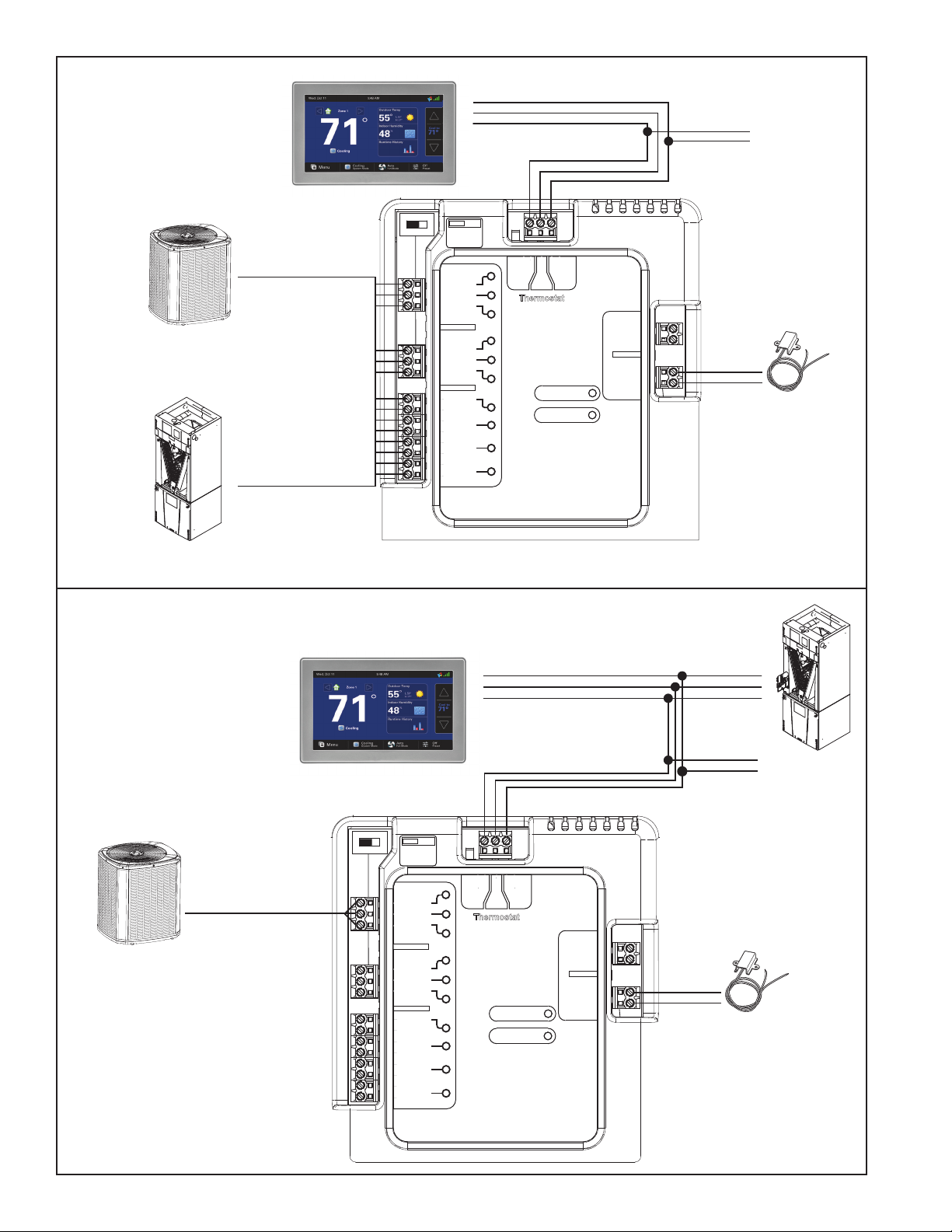
PCPOCOM
Zone Panel Connections
S-Series Furnace with
S-Series Furnace with Coil
Variable Speed HP/AC
Non-Communicating Furnace with Coil
and Communicating Outdoor Unit
See Relay Panel
Installer’s Guide
for specific
wiring instructions.
R
B/C
W1
W2
G
BK
Non-Communicating
Control
To R & B
NORM
0 SOV
Y1 Stg1
Y2 Stg2
W1 Stg1
W2 Stg2
W3 Stg3
G
BK
Hum
Hum
Aux1
Aux1
Aux2
Aux2
Dual Fuel
Switch
PWM
DUAL
Fan
24 Vac
24 Vac
24 Vac
Only
Only
Only
Relay Panel
B
R
D
D R
Data
Hot
Thermostat
and Indoor Unit
HVAC System
B
Comm
Bit Master
B
R
D
Communicating
Outdoor Unit
D
B
To Zone Panel
See Page 5 for
Zone Panel
Connections
Com
RS
RS
Indoor
Remote
Sensors
ODT
ODT
Outdoor
Wired Remote
Outdoor Sensor
BAYSEN01ATEMPA
(may be wired to Control)
From Communicating
Indoor Unit
or Relay Panel
1 - 4
1 - 4
ZONES
ZONES
5 - 8
5 - 8
BRBD D
BD B
R
Gnd/Grn
Common
Indoor/
24V
Outdoor
Zone Panel
Signal/Blk
Relay Panel
Trans.
(Only Use For
PO/Open
Zones 5-8)
Static Press
+5V/Red
ByPass
PC/Close
Discharge Air
Common
Discharge Air
PO/Open
Return Air
Zone
1 or 5
PC/Close
Return Air
Common
Mixed Air
PO/Open
Temperature
Mixed Air
Zone
2 or 6
PC/Close
Zone 1 or 5
Common
Sensors
Zone 1 or 5
PO/Open
Zone Dampers
Zone 2 or 6
Zone
3 or 7
PC/Close
Zone 2 or 6
Common
Comm
Zone 3 or 7
PO/Open
Remote Indoor
Zone 3 or 7
Zone
4 or 8
PC/Close
Zone 4 or 8
Zone 4 or 8
Zone Panel
Zone Panel
(Zones 5-8)
B
D
Clamp-style Connectors
D
R
B
Static Pressure
Transducer
(OPTIONAL)
Temperature
Sensor(s)
Discharge
(REQUIRED)
Return
(OPTIONAL)
Mixed
(OPTIONAL)
Reserved
Reserved
Reserved
Common
PO/Open
PC/Closed
Common
PO/Open
PC/Closed
Common
PO/Open
PC/Closed
Common
PO/Open
PC/Closed
Field-Supplied 24V
Transformer
TRANS.
1 - 4
1 - 4
ZONES
ZONES
5 - 8
5 - 8
Zone
1 or 5
Zone
2 or 6
Zone
3 or 7
Zone
4 or 8
BRBD D
BD B
R
Comm Zone Sensor
2nd Zone Panel
24V
Trans.
Sensors
Gnd/Grn
Signal/Blk
Static Press
+5V/Red
Discharge Air
Discharge Air
Return Air
Return Air
Mixed Air
TemperatureNon Comm Zone Sensor
Mixed Air
Zone 1 or 5
Zone 1 or 5
Zone 2 or 6
Zone 2 or 6
Zone 3 or 7
Zone 3 or 7
Zone 4 or 8
Zone 4 or 8
Comm
Indoor/
Outdoor
Relay Panel
Zone Dampers
Comm
0 1
CNT06430
24VAC 50/60Hz
1.5VA
60s
18in-lb(2Nm)
Made in Switzerland
Trane US, Inc.
MANUAL
GEAR
III
!
RELEASE
Non-Communicating Zone Sensor(s)
(ZZSENSAL0400A)
Zone Panel
Damper(s)
(Zones 1-4)
RB D
Communicating Zone Sensor(s)
*ZONE940AC52ZA
5
Page 6
Section 3. Installation
Zone Panel
ZONES
1 - 4
5 - 8
Zone Dampers
Sensors
Reserved
Reserved
Reserved
Static Press
Gnd/Grn
Signal/Blk
+5V/Red
Temperature
Non Comm Zone Sensor
Discharge Air
Discharge Air
Return Air
Return Air
Mixed Air
Mixed Air
Zone 1 or 5
Zone 1 or 5
Zone 2 or 6
Zone 2 or 6
Zone 3 or 7
Zone 3 or 7
Zone 4 or 8
Zone 4 or 8
Zone
1 or 5
I
n
door/
Relay Panel
Comm
Outdoor
Comm Zone Sensor/
2nd Zone Panel
24V
Trans.
Common
PO/Open
PC/Closed
Zone
2 or 6
Common
PO/Open
PC/Closed
Zone
3 or 7
Common
PO/Open
PC/Closed
Zone
4 or 8
Common
PO/Open
PC/Closed
Comm
R
BD B
B
R
BD
D
Zone Dampers
Sensors
Reserved
Reserved
Reserved
Static Press
Gnd/Grn
Signal/Blk
+5V/Red
Temperature
Non Comm Zone Sensor
Discharge Air
Discharge Air
Return Air
Return Air
Mixed Air
Mixed Air
Zone 1 or 5
Zone 1 or 5
Zone 2 or 6
Zone 2 or 6
Zone 3 or 7
Zone 3 or 7
Zone 4 or 8
Zone 4 or 8
Zone
1 or 5
Indoor/
Relay Panel
Outdoor
Comm Zone Sensor/
2nd Zone Panel
24V
Trans.
Common
PO/Open
PC/Closed
Zone
2 or 6
Common
PO/Open
PC/Closed
Zone
3 or 7
Common
PO/Open
PC/Closed
Zone
4 or 8
Common
PO/Open
PC/Closed
Comm
R
BD B
B
R
BD
D
ZONES
1 - 4
5 - 8
Zone Dampers
Sensors
Reserved
Reserved
Reserved
Static Press
Gnd/Grn
Signal/Blk
+5V/Red
Temperature
Non Comm Zone Sensor
Discharge Air
Discharge Air
Return Air
Return Air
Mixed Air
Mixed Air
Zone 1 or 5
Zone 1 or 5
Zone 2 or 6
Zone 2 or 6
Zone 3 or 7
Zone 3 or 7
Zone 4 or 8
Zone 4 or 8
Zone
1 or 5
Indoor/
Relay Panel
Comm
Outdoor
Comm Zone Sensor/
2nd Zone Panel
24V
Trans.
Common
PO/Open
PC/Closed
Zone
2 or 6
Common
PO/Open
PC/Closed
Zone
3 or 7
Common
PO/Open
PC/Closed
Zone
4 or 8
Common
PO/Open
PC/Closed
Comm
R
BD B
B
R
BD
D
ZONES
1 - 4
5 - 8
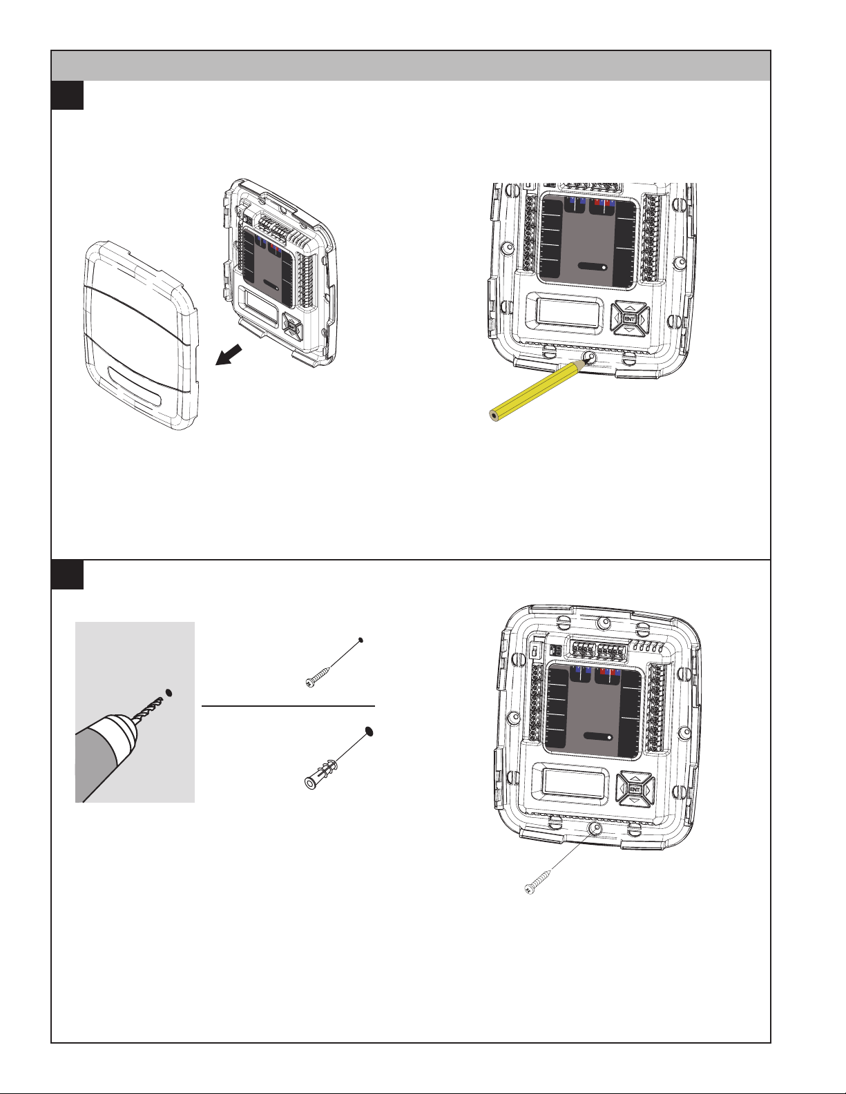
1A
Preparation
The unit’s rugged design allows installation in closet, attic or other non-condensing locations free from
obstructions or other hazards.
Remove cover by grasping at edges and gently
pulling the cover straight towards you. It should
release without much effort.
Mount Panel
1B
DRILL HOLES
1/8” for screws
into studs
3/16” for drywall
anchors
Mounting to studs: Drill 1/8” pilot holes in the four
locations marked above.
Mark four holes on the wall using the base as a
template. A level may be used to ensure accuracy.
Mounting to drywall:
If mounting to drywall with no studs behind it,
enlarge pilot holes to 3/16” for anchors (included
with the control).
Gently tap anchors into the holes.
6 18-HD66D1-4
Attach base to wall using four screws provided.
Do not overtighten.
Page 7
3.1 General Wiring Considerations
▲
CAUTION
!
▲
WARNING
!
Static Press
Gnd/Grn
Signal/Blk
+5V/Red
1 - 4
5 - 8
Indoor/
Relay Panel
Comm
Outdoor
Comm Zone Sensor/
2nd Zone Panel
24V
Trans.
R
BDB
BRBD D
Static Press
Gnd/Grn
Signal/Blk
+5V/Red
Discharge Air
Discharge Air
Comm
Outdoor
24V
Trans.
R
BDB
B
R
BD D
Zone Dampers
Sensors
Reserved
Reserved
Reserved
Static Press
Gnd/Grn
Signal/Blk
+5V/Red
TemperatureNon Comm Zone Sensor
Discharge Air
Discharge Air
Return Air
Return Air
Mixed Air
Mixed Air
Zone 1 or 5
Zone 1 or 5
Zone 2 or 6
Zone 2 or 6
Zone 3 or 7
Zone 3 or 7
Zone 4 or 8
Zone 4 or 8
Zone
1 or 5
Indoor/
Relay Panel
Comm
Outdoor
Comm Zone Sensor/
2nd Zone Panel
24V
Trans.
Common
PO/Open
PC/Closed
Zone
2 or 6
Common
PO/Open
PC/Closed
Zone
3 or 7
Common
PO/Open
PC/Closed
Zone
4 or 8
Common
Comm
R
BD B
B
R
BD
D
ZONES
1 - 4
5 - 8
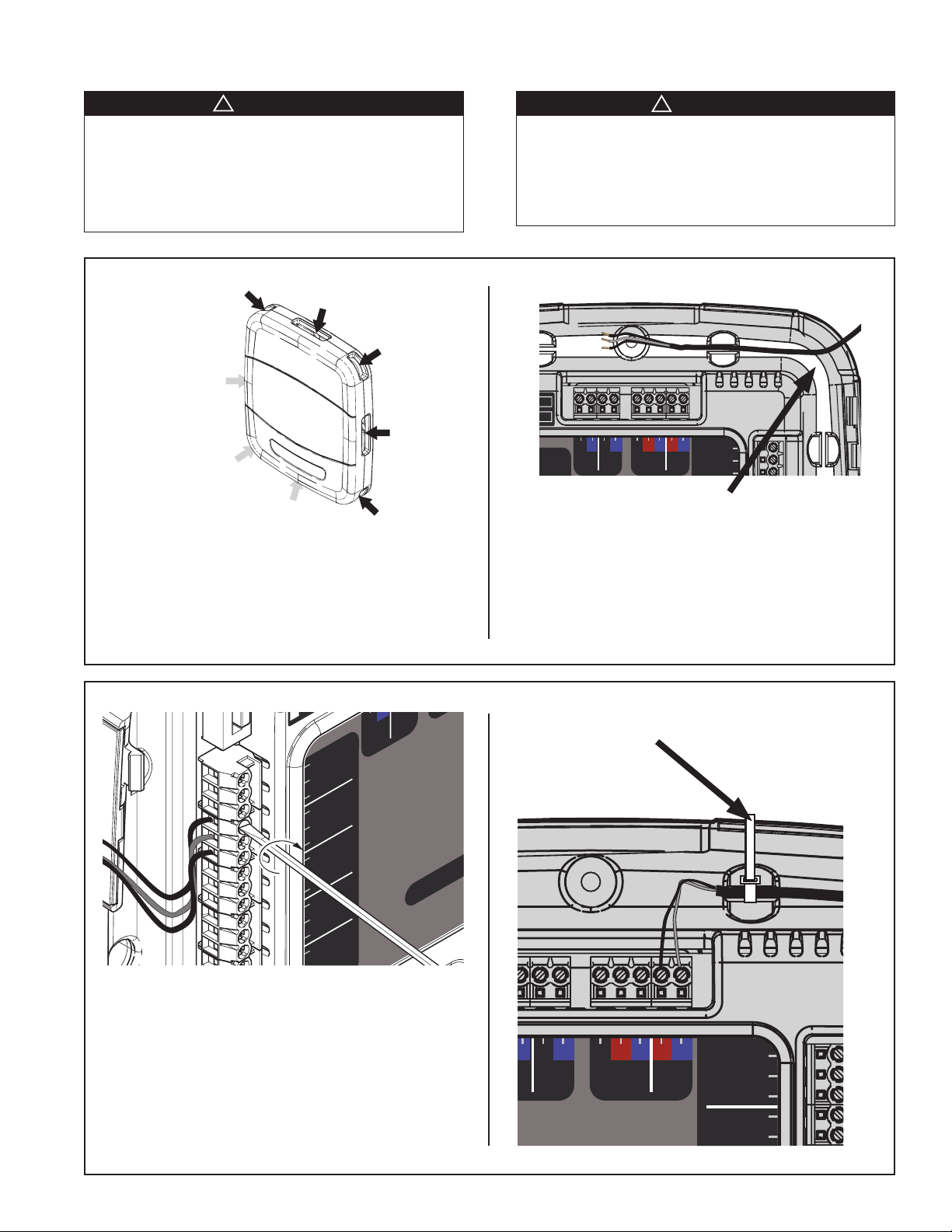
LIVE ELECTRICAL COMPONENTS!
During installation, testing, servicing, and troubleshooting of this product, it may be necessary to work with live
electrical components. Failure to follow all electrical safety
precautions when exposed to live electrical components
could result in death or serious injury.
Wires may
enter at
any of 8
locations
Zone Panel
Wires may enter the Zone Panel through openings
on each corner and at the center of each side.
Necessary wire lengths should be considered when
determining entry points.
CAUTION: EQUIPMENT DAMAGE HAZARD - Improper
wiring can lead to equipment damage. Follow the Terminal
Connection information carefully to ensure the control is
wired properly. After wires are secure, bare wires
MUST NOT touch each other. See the Field Wiring Diagrams for specific system applications.
Route wires into “Raceways”
Run wires within the recessed wire “raceway”. Be
sure there is ample length to reach the connectors.
7
Using 1/8” blade screwdriver, attach all wires
securely to the proper terminals on the Zone
Panel. (See the Field Wiring Diagrams in the
following section.)
NOTE: The wire terminal blocks may be removed
for convenience in wiring. Ensure the terminal
block properly aligns with the pins when resetting.
Secure all wires with the supplied wire ties.
Comm Zone Sensor/
2nd Zone Panel
Page 8
Zone Dampers
Sensors
Reserved
Reserved
Reserved
Static Press
Gnd/Grn
Signal/Blk
+5V/Red
TemperatureNon Comm Zone Sensor
Discharge Air
Discharge Air
Return Air
Return Air
Mixed Air
Mixed Air
Zone 1 or 5
Zone 1 or 5
Zone 2 or 6
Zone 2 or 6
Zone 3 or 7
Zone 3 or 7
Zone 4 or 8
Zone 4 or 8
Zone
1 or 5
ZONES
1 - 4
5 - 8
Indoor/
Relay Panel
Comm
Outdoor
Comm Zone Sensor/
2nd Zone Panel
24V
Trans.
Common
PO/Open
PC/Closed
Zone
2 or 6
Common
PO/Open
PC/Closed
Zone
3 or 7
Common
PO/Open
PC/Closed
Zone
4 or 8
Common
PO/Open
PC/Closed
Comm
R
BDB
BRBD D
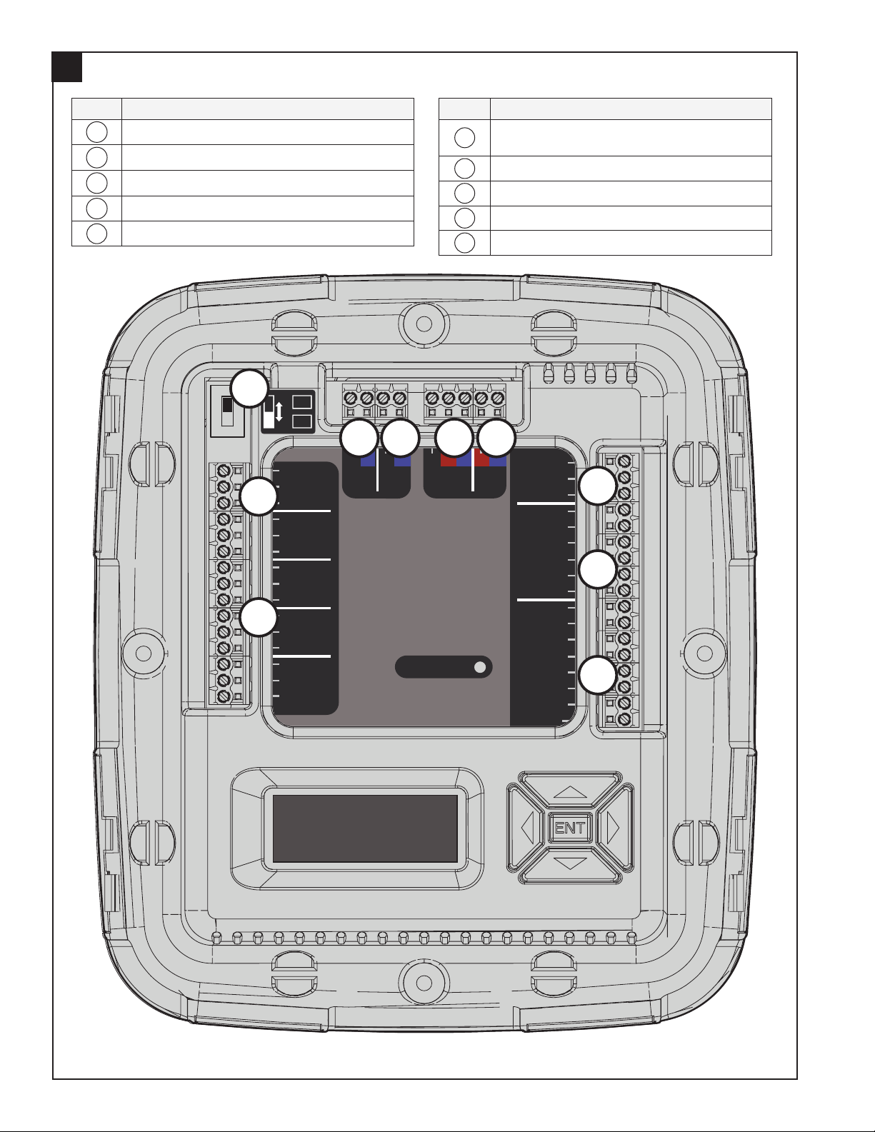
Observe Terminal Locations
2
KEY Identification
A
B
C
D
E
Primary Panel or Secondary Panel
From Indoor Unit or Relay Panel
To Communicating Outdoor Unit
Zone Dampers
Reserved
C
B
KEY Identification
F
G
H
I
J
D E F G
Communicating Zone Sensors / 2nd Zone
Panel
Dedicated 24V Transformer
Static Pressure Sensors
Temperature Sensors
Non-Communicating Zone Sensors
H
I
A
J
8 18-HD66D1-4
Page 9
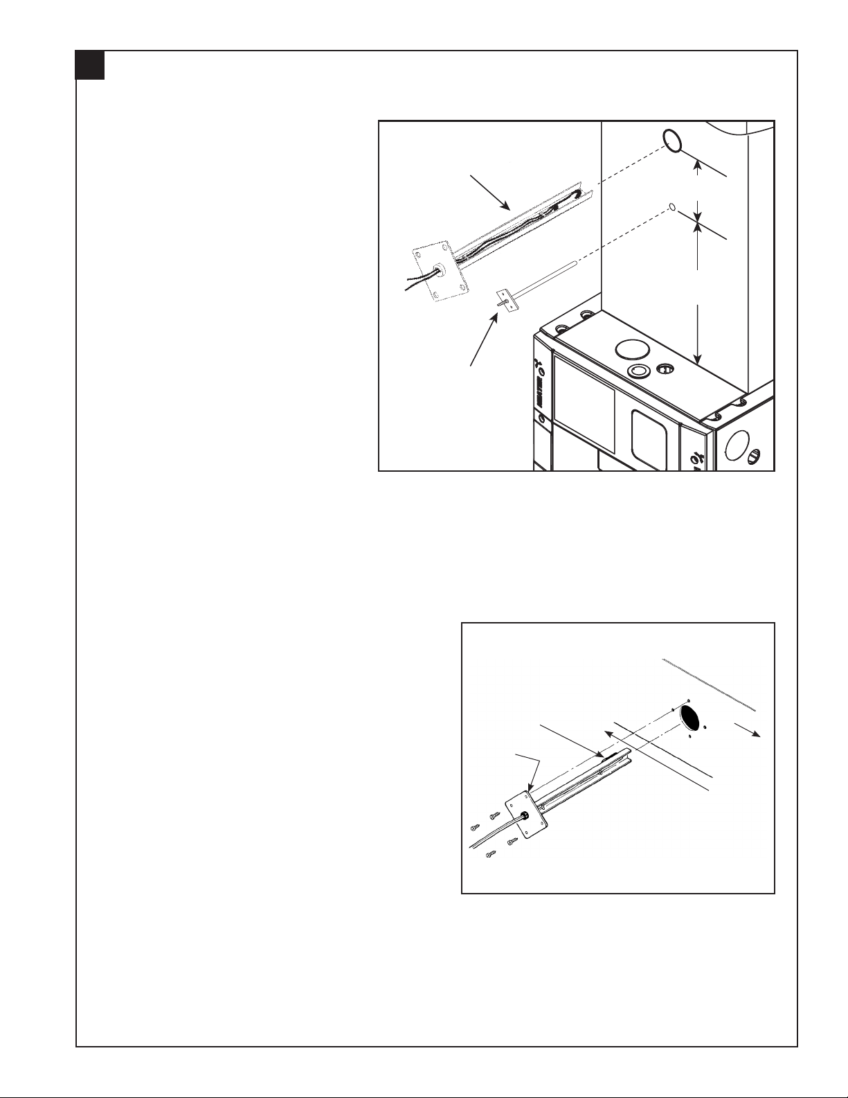
Mount Discharge Temperature Sensor
Discharge
Temp
Sensor
6” Min.
2” Min.
Static
Pressure
Probe
(Supply)
3
REQUIRED: A Discharge
Temperature Sensor is required.
The Discharge Temperature
Sensor (DTS) must be mounted
a minimum of 8” above the edge
of the supply duct (additional
distance is preferred when
possible). In addition, the
DTS must be 2” above the
Static Pressure Probe if used.
Locate the DTS in an area of
the discharge air duct where
less air turbulence is expected.
Avoid dead air areas where
representative discharge air
temperatures may not exist.
OPTIONAL: A return air sensor
(SEN 00462) may be installed to
monitor the return air temperature
at the indoor unit. The mixed
air sensor (SEN 00462) is used
to monitor mix air when using
bypass (future use).
Determine the proper positioning of the DTS as
follows:
• If a radiant heat source such as an electric
Drill a hole for mounting the DTS. A minimum hole
size of 7/8” will be required.
The mounting plate can be used as a template to
locate the four screw holes.
9
heater is in line of sight from the thermistor,
position the sensor so that the black thermistor
faces away from the radiant heat source. (This
will prevent a false reading due to the radiant
effect on the thermistor.)
Thermistor
Apply
Sealant
Airflow
Radiant
Heat
Source
Page 10

Discharge
Temp
Sensor
6” Min.
2” Min.
6” Min.
Static
Pressure
Probe
(Supply)
Static
Pressure
Probe
(Return)
Mount Supply Air and Return Air Static Pressure Probes
4
OPTIONAL: Static Pressure probes
are only required when using Auto Zone
Sizing.
The supply static pressure sensor must
be mounted a minimum of 6” above the
unit cabinet and the return probe must
be mounted a minimum of 6” below the
unit cabinet. Additional distance from
the cabinet is preferred when possible.
Mount the probes in a central area
of duct away from turns, transitions,
take offs or other areas of potential
turbulence.
Drill a hole of 1/4” minimum to accept
the Static Pressure probes.
Insert and mount the sensor as
shown. Insulate the sensor to prevent
condensation.
NOTE: The static probes are used for
Automatic Zone Sizing and are placed
outside the Coil and Electronic Air
Cleaner (if used). The static pressure
reading references external duct static;
not the overall system static imposed
upon the blower motor.
10 18-HD66D1-4
Page 11

Mount Static Pressure Transducer Enclosure
5
Mount the Static Pressure Transducer Enclosure
in an area between the two static probes. The
location should be easily accessible, and in a
position where the tubing can reach both static
pressure probes.
Connect Static Pressure Tubing
6
NOTE: Cut tubing to the proper length for the
supply and return static pressure probes.
Attach the tubing to each of the static pressure
probes and route the tubing back to the enclosure.
Support the tubing to eliminate any kinks. Slide
the return & supply tubing through the hole in the
enclosure.
Attach the tubing to the Pressure Transducer.
The tube from the supply duct will go on the bottom
barb of the transducer.
The tube from the return duct will go on the top
barb of the transducer (the top barb is marked with
a “–” sign).
Install a tubing clamp on each of the Static
Pressure Transducer tubing connectors.
Mount the Pressure Transducer inside the
enclosure using the two screws as shown.
Ensure the tubing is properly supported and not
kinked in any location.
Note: Tubing must be connected as
shown for proper operation
return
tubing
supply
tubing
tubing
clamp
Route wiring through hole in enclosure.
Attach the tubing to the static pressure probes
using the remaining tube clamps.
11
Page 12

7
Sensors
Static Press
Gnd/Grn
Signal/Blk
+5V/Red
TemperatureNon Comm Zone Sensor
Discharge Air
Discharge Air
Return Air
Return Air
Mixed Air
Mixed Air
Zone 1 or 5
Zone 1 or 5
Zone 2 or 6
24V
Trans.
R
BD D
Sensors
Static Press
Gnd/Grn
Signal/Blk
+5V/Red
TemperatureNon Comm Zone Sensor
Discharge Air
Discharge Air
Return Air
Return Air
Mixed Air
Mixed Air
Zone 1 or 5
24V
Trans.
R
BD D
Connect Temperature Sensor Wires
Connect the required Discharge Air Temperature
Sensor wires to the terminals marked “Discharge
Air” as shown at right. Use a dedicated wire
bundle.
REQUIRED
Terminal
Name
Temperature Sensors
Description Color Used:
OPTIONAL
Discharge Air Discharge Air Sensor
Discharge Air Discharge Air Sensor
Return Air
Return Air
Mixed Air
Mixed Air
Optional Return Air Sensor
Optional Return Air Sensor
Optional Mixed Air Sensor
Optional Mixed Air Sensor
OPTIONAL: If using Return Air or Mixed Air temperature sensors, connect their wires to “Return Air” or
“Mixed Air” respectively.
NOTE: Wiring for all temperature sensors must be run in bundles separate from other 24 VAC circuits.
Connect Static Pressure Transducer Wires
8
Connect the Green wire from the Static Pressure
transducer to the terminal labeled “Gnd/Grn.”
Connect the Black wire from the Static Pressure
transducer to the terminal labeled “Signal/Blk.”
Connect the Red wire from the Static Pressure
transducer to the terminal labeled “+5V/Red.”
Place the cover on the Pressure Transducer
Enclosure once the tubing is attached and wiring is
complete.
Terminal
Name
Gnd/Grn Ground
Signal/Blk Output Signal (5VDC)
+5V/Red Power (5VDC)
NOTE: Wiring for the pressure sensor must be run in bundles separate from other 24 VAC circuits.
12 18-HD66D1-4
Static Pressure Sensor
Description Color Used:
Page 13

Connect Communicating Indoor Unit/Relay Panel
Static Press
Gnd/Grn
Signal/Blk
+5V/Red
Indoor/
Relay Panel
Comm
Outdoor
Comm Zone Sensor/
2nd Zone Panel
24V
Trans.
R
BDB
B
R
BD D
Static Press
Gnd/Grn
Signal/Blk
+5V/Red
Indoor/
Relay Panel
Comm
Outdoor
Comm Zone Sensor/
2nd Zone Panel
24V
Trans.
R
BDB
B
R
BD D
Static Press
Gnd/Grn
Signal/Blk
+5V/Red
Indoor/
Relay Panel
Comm
Outdoor
Comm Zone Sensor/
2nd Zone Panel
24V
Trans.
R
BDB
B
R
BD D
9
Connect the Indoor Unit or Relay Panel B and D
low voltage wiring to the Zone Panel’s “Indoor/
Relay Panel” B and D terminals.
Indoor Unit or Relay Panel Connections
Terminal
Name
Description Color Used:
D Data
B Common
NOTE: R from the Indoor Unit/Relay Panel is not
connected because power is provided from a field
supplied 24VAC transformer.
Connect Wiring to Communicating Outdoor Unit
10
The Zone Panel provides an optional low voltage
connection point for a communicating outdoor unit.
The communicating outdoor requires B and D from
one location; this can either be from the indoor unit
or the Zone Panel.
NOTE: If a non-communicating outdoor unit is
installed, these connections will not be used.
Outdoor Unit Connections
Terminal
Name
Description Color Used:
D Data
B Common
Connect Wiring to Communicating Zone Sensors and 2nd Zone Panel (if used)
11
Connect wiring (D, R, B) between each Communicating Zone
Sensor using the provided clamp-style wire connectors. If
required, a 2nd Zone Panel can also be connected.
13
Power Supply Connections
Terminal
Name
Description Color Used:
D Data
R 24V Hot
B Common
See Communicating Zone Sensor Installer’s Guide for setup information
Page 14

Mount the Zone Panel 24V Power Supply
Static Press
Gnd/Grn
Signal/Blk
+5V/Red
Indoor/
Relay Panel
Comm
Outdoor
Comm Zone Sensor/
2nd Zone Panel
24V
Trans.
R
BDB
B
R
BD D
Zone Dampers
Sensors
Reserved
Reserved
Reserved
Static Press
Gnd/Grn
Signal/Blk
+5V/Red
TemperatureNon Comm Zone Sensor
Discharge Air
Discharge Air
Return Air
Return Air
Mixed Air
Mixed Air
Zone 1 or 5
Zone 1 or 5
Zone 2 or 6
Zone 2 or 6
Zone 3 or 7
Zone 3 or 7
Zone 4 or 8
Zone
1 or 5
ZONES
1 - 4
5 - 8
Indoor/
Relay Panel
Comm
Outdoor
Comm Zone Sensor/
2nd Zone Panel
24V
Trans.
Common
PO/Open
PC/Closed
Zone
2 or 6
Common
PO/Open
PC/Closed
Zone
3 or 7
Common
PO/Open
PC/Closed
Zone
4 or 8
Common
PO/Open
PC/Closed
Comm
R
BDB
B
R
BD D
12
A separate, field-supplied 24 volt transformer is required
to power the Zone Panel, communicating sensors
and dampers. VA sizing of the transformer will be
dependant on the total VA of all installed zone panels,
communicating sensors and zone dampers. Connect this
dedicated 24 volt source to the R and B terminals.
NOTE: To prevent possible communication errors,
connect the B/common of the field-supplied Zone Panel
transformer to the indoor unit B/common or equipment
ground.
EXAMPLE:
Transformer Sizing Example (8 Zone System, 1 Damper per Zone)
Component Qty VA (ea) Total VA
Zone Panel 2 2 4
Zone Dampers* 8 1.5 12
Communicating
Sensor
4 2 8
Minimum Transformer VA Required 24
*Add the VA of each communicating sensor
Power Supply Connections
Terminal
Name
Description Color Used:
R 24V Hot
B Common
Connect the Dampers
13
The dampers will have the same terminal
designation as the Zone Panel.
Zone Dampers
For each damper:
• Connect Common from the damper to
Common on the Zone Panel.
• Connect PO/Open from the damper to
PO/Open on the Zone Panel.
• Connect PC/Close from the damper to
PC/Close on the Zone panel.
Repeat this for each damper installed (see
the damper installer’s guide).
14 18-HD66D1-4
Terminal Name Description Color Used:
Reserved Common
Reserved Power Open
Reserved Power Close
Common Common
PO/Open Power Open
or 5*
Zone 1
PC/Close Power Close
Common Common
PO/Open Power Open
or 6*
Zone 2
PC/Close Power Close
Common Common
PO/Open Power Open
or 7*
Zone 3
PC/Close Power Close
Common Common
PO/Open Power Open
of 8*
Zone 4
PC/Close Power Close
* Zones 5–8 are only when a second zone panel is used.
NOTES:
• 60 second drive dampers are the default. 15-60 second dampers
can be used, timing must be set at the 950/1050 Control.
• Up to 4 dampers may be used per zone (6 VA Max.).
• Mixing dampers from multiple manufacturers in the same zone is
not permitted.
Page 15

Connect Non-Communicating Zone Temperature Sensors
Sensors
Static Press
Gnd/Grn
Signal/Blk
+5V/Red
TemperatureNon Comm Zone Sensor
Discharge Air
Discharge Air
Return Air
Return Air
Mixed Air
Mixed Air
Zone 1 or 5
Zone 1 or 5
Zone 2 or 6
Zone 2 or 6
Zone 3 or 7
Zone 3 or 7
Zone 4 or 8
Zone 4 or 8
24V
Trans.
R
BD D
Reserved
Gnd/Grn
Signal/Blk
ZONES
1 - 4
5 - 8
Indoor/
Relay Panel
Comm
Comm Zone Sensor/
2nd Zone Panel
24V
R
BDB
B
R
BD D
14
If using non-communicating zone temperature sensors, connect them to the non-communicating
zone terminal block. These are two wire sensors and are not polarity sensitive. Attach each
sensor to its respective zone.
NOTE: When using communicating zone sensors, the non-communicating indoor terminal block
will not be used.
IMPORTANT: If using the 950/1050 Control as Zone 1, do not connect a non-communicating
zone sensor to Zone 1 slot.
NOTE: The 1050 will always be addressed as Zone 1. If using a remote sensor it will need
configured and wired directly to the 950/1050
subbase. The 940 can also be used as a remote
sensor for Zone 1 if it is tied into R, D, B and
addressed as Zone 1.
Non-Communicating Indoor Temperature Sensors
Terminal
Name
Zone 1
Zone 1
Zone 2
Zone 2
Zone 3
Zone 3
Zone 4
Zone 4
Non-Communicating Zone Temp Sensor
Non-Communicating Zone Temp Sensor
Non-Communicating Zone Temp Sensor
Non-Communicating Zone Temp Sensor
Non-Communicating Zone Temp Sensor
Non-Communicating Zone Temp Sensor
Non-Communicating Zone Temp Sensor
Non-Communicating Zone Temp Sensor
Description
Color
Used:
15
Zone Switch Position
Set the Zone Switch to the up position if only one zone
panel is used (4 zones or less).
If two panels are used (5 or more zones), the zone
switch must be moved down on the second zone panel
(the panel that is controlling zones 5 through 8).
NOTE: If the Zone Switch position is changed after
power has been applied, an additional Zone Panel will
be created. Use the Summary Screen in the 950/1050
Control to remove the offline device.
15
Page 16

Section 4. Zoning Setup
Required Steps before enabling zoning:
1) Zone Panel must be powered (24VAC transformer)
2) Zone Panel must be connected to communicating bus (D, B)
3) All non-communicating zone temperature sensors must be connected to corresponding zone slots
4) All communicating zone temperature sensors must be addressed to corresponding zone number
5) All dampers should be installed and connected to corresponding zone slot
6) Discharge Temperature Sensor must be connected
7) Install and wire Differential Static Pressure Sensor and probes (only required for Auto Zone Sizing)
STEP 1 - Enable Zoning
Enter the Installer Setup section on the 950/1050
Control:
Home screen --> Menu --> Service --> Technician
Access* --> Proceed --> Installer Setup
Move through the Standard Installation Set Up
options and Enable Zoning on the first screen of
Group 2.
Important: Must use a Trane/American
Standard manufactured indoor unit with a
variable speed blower. If a TAM9, TEM8, or TAM8
air handler is being used, verify the Airflow
Mode selected on the air handler CDA or 7
segment display is set to Constant CFM.
STEP 2 - Damper Travel Time
Select the travel time that matches the dampers.
NOTE: Trane and American Standard dampers
use a 60 second travel time.
NOTE: The zone control can handle many types of
dampers, but all dampers in the system must have
the same drive time (15 to 60 seconds) and must
be power open/power close. Spring controlled
dampers are not allowed. See the damper
installation guide for additional information.
STEP 3 - Auto Detect Dampers
The zone control will send out a signal to open and
close the dampers when “Yes” is selected. The
control will see the load on each damper slot and
automatically configure the number of zones with
dampers detected.
STEP 4 - Manually Detect Dampers
The dampers will be automatically checked if auto
damper detection was selected.
The technician will need to manually select the
appropriate dampers if auto damper detection is
not used.
16 18-HD66D1-4
Page 17

STEP 5 - Auto Zone Sizing
The zone control has the ability to energize the
blower and modulate dampers to determine how
much air each zone can handle. The Static
Pressure kit is required to use Auto Zone Sizing.
NOTE: All zones less than 25% cannot be a
voting zone (See STEP 7). Press “Yes” to accept
or press “No” to change the size of the zone.
STEP 6 - Zone Size Adjustment
Auto zone sizing will calculate the amount of air that the
ductwork for each zone can handle. There are three
available options:
• The Normal mode calculates zone sizes based on an
average external duct static
• The Less Aggressive option calculates on a lower
external duct static and will deliver a reduced amount
of air into each calling zone. This strategy provides a
quieter air flow system, but increases the amount of
excess air that must be managed. This may increase
the amount of excess air that is relieved into other zones.
• The More Aggressive option calculates on a higher external duct static and will deliver an increased
amount of air into each calling zone. This strategy may produce a noisier air flow system, but reduces the
amount of excess air that must be managed. This may reduce the amount of excess air that is relieved
into other zones.
It is recommended to begin with the Normal mode. You can re-run auto zone sizing with Less Aggressive if
a customer is concerned about air noise, or at More Aggressive if a customer is concerned about relief air or
simply desires higher velocity air flow rates.
NOTE: Auto Zone Sizing typically takes 10 to
15 minutes for 2 – 4 zone systems and up to 30
minutes for 5 – 8 zone systems.
If Auto Zone Sizing returns an error, follow the onscreen prompts for diagnosing the failure.
The auto zone sizing process calculates and
displays the size of each zone. The technician can
select and modify any zone setting to satisfy the
homeowners air flow desires.
17
Page 18

Damper
Diameter
Damper
Diameter
Damper
Diameter
Damper
Diameter
Less Aggressive
Normal
More Aggressive
Less Aggressive
Normal
More Aggressive
Less Aggressive
Normal
More Aggressive
Less Aggressive
Normal
More Aggressive
Damper
Diameter
Damper
Diameter
CFM CFM
Damper
Diameter
Damper
Diameter
CFM CFM
500 600 700 800
4" 9% 12% 16% 4" 7% 10% 13% 4" 6% 9% 11% 4" 6% 8% 10%
6" 19% 27% 35% 6" 16% 23% 29% 6" 14% 19% 25% 6" 12% 17% 22%
7" 26% 36% 46% 7" 22% 30% 38% 7" 19% 26% 33% 7" 16% 23% 29%
8" 34% 48% 62% 8" 29% 40% 52% 8" 25% 34% 44% 8" 22% 30% 39%
9" 44% 61% 79% 9" 36% 51% 66% 9" 31% 44% 56% 9" 27% 38% 49%
10" 54% 78% 98% 10" 45% 65% 82% 10" 39% 56% 70% 10" 34% 49% 61%
12" 79% 100% 100% 12" 66% 87% 117% 12" 56% 74% 100% 12" 49% 65% 88%
14" 100% 100% 100% 14" 87% 100% 100% 14" 74% 100% 100% 14" 65% 94% 100%
16" 100%
100% 100% 16" 100% 100% 100% 16" 99% 100% 100% 16" 86% 100% 100%
18" 100% 100% 100% 18" 100% 100% 100% 18" 100% 100% 100% 18" 100% 100% 100%
Damper
Diameter
Damper
Diameter
Damper
Diameter
Damper
Diameter
Damper
Diameter
CF
M CFM
Damper
Diameter
Damper
Diameter
Damper
Diameter
CFM CFM
Less Aggressive
Normal
More Aggressive
Less Aggressive
Normal
More Aggressive
Less Aggressive
Normal
More Aggressive
Less Aggressive
Normal
More Aggressive
Damper
Diameter
Damper
Diameter
Damper
Diameter
CFM CFM
Damper
Diameter
CFM
900 1000 1100
1200
4" 5% 7% 9% 4" 4% 6% 8% 4" 4% 5% 7% 4" 4% 5% 7%
6" 11% 15% 19% 6" 10% 14% 18% 6" 9% 12% 16% 6" 8% 11% 15%
7" 14% 20% 26% 7" 13% 18% 23% 7" 12% 16% 21% 7" 11% 15% 19%
8" 19% 27% 34% 8" 17% 24% 31% 8" 16% 22% 28% 8" 14% 20% 26%
9" 24% 34% 44% 9" 22% 31% 40% 9" 20% 28% 36% 9" 18% 25% 33%
10" 30% 43% 54% 10" 27% 39% 49% 10" 25% 35% 45% 10" 23% 33% 41%
12" 44% 58% 78% 12" 40% 52% 70% 12" 36% 47% 64%
12"
33%
43%
58%
14" 58% 84% 100% 14" 52% 76% 96% 14" 47% 69% 87% 14" 43% 63% 80%
16" 77% 100% 100% 16" 69% 98% 100% 16" 63% 89% 100%
16"
58%
81%
100%
18" 100% 100% 100% 18" 90% 100% 100% 18" 82% 100% 100% 18" 75% 100% 100%
Damper
Diameter
Damper
Diameter
Damper
Diameter
CFM CFM
Damper
Diameter
Damper
Diameter
Damper
Diameter
CFM
Damper
Diameter
Damper
Diameter
CFM
Less Aggressive
Normal
More Aggressive
Less Aggressive
Normal
More Aggressive
Less Aggressive
Normal
More Aggressive
Less Aggressive
Normal
More Aggressive
CFM
Damper
Diameter
Damper
Diameter
CFM CFM
Damper
Diameter
Damper
Diameter
1300 1400 1500
CFM
1600
4" 3% 5% 6% 4" 3% 4% 6% 4" 3% 4% 5% 4" 3% 4% 5%
6" 7% 10% 13% 6" 7% 10% 13% 6" 6% 9% 12% 6" 6% 8% 11%
7" 10% 14% 18% 7" 9% 13% 16% 7" 9% 12% 15% 7" 8% 11% 14%
8" 13% 18% 24% 8" 12% 17% 22% 8" 11% 16% 21% 8" 11% 15% 19%
9" 17% 23% 30% 9" 16% 22% 28% 9" 15% 20% 26% 9" 14% 19% 25%
10" 21% 30% 38% 10" 19% 28% 35% 10" 18% 26% 33% 10" 17% 24% 31%
12" 30% 40% 54% 12" 28% 37% 50% 12" 26% 35% 47% 12" 25% 33% 44%
14" 40% 58% 73% 14" 37% 54% 68% 14" 35% 50% 64% 14" 33% 47% 60%
16"
53% 75% 96% 16" 49% 70% 89% 16" 46% 65% 83% 16" 43% 61% 78%
18" 69% 96% 100% 18" 64% 89% 100% 18" 60% 83% 100% 18" 56% 78% 100%
Damper
Diameter
Damper
Diameter
Damper
Diameter
CFM
Damper
Diameter
Damper
Diameter
CFM CFM
Damper
Diameter
Damper
Diameter
Damper
Diameter
Less Aggressive
Normal
More Aggressive
Less Aggressive
Normal
More Aggressive
Less Aggressive
Normal
More Aggressive
Less Aggressive
Normal
More Aggressive
Damper
Diameter
Damper
Diameter
Damper
Diameter
CFM CFM cfm
Damper
Diameter
CFM
1800 1900 2000 2200
4" 2% 3% 4% 4" 2% 3% 4% 4" 2% 3% 4% 4" 2% 3% 4%
6" 5% 8% 10% 6" 5% 7% 9% 6" 5% 7% 9% 6" 4% 6% 8%
7" 7% 10% 13% 7" 7% 9% 12% 7" 7% 9% 12% 7" 6% 8% 10%
8" 10% 13% 17% 8" 9% 13% 16% 8" 9% 12% 16% 8" 8% 11% 14%
9" 12% 17% 22% 9" 11% 16% 21% 9" 11% 15% 20% 9" 10% 14% 18%
10" 15% 22% 27% 10" 14% 21% 26% 10" 14% 20% 25% 10" 12% 18% 22%
12" 22% 29% 39% 12" 21% 27% 37% 12" 20% 26% 35% 12" 18% 24% 32%
14" 29% 42% 53% 14" 27% 40% 50% 14" 26% 38% 48% 14" 24% 34% 43%
16" 38%
54% 69% 16" 36% 51% 66% 16" 35% 49% 63% 16" 31% 44% 57%
18" 50% 69% 89% 18" 47% 66% 84% 18" 45% 63% 80% 18" 41% 57% 73%
Damper
Diameter
Damper
Diameter
Damper
Diameter
CFM CFM cfm
Damper
Diameter
CFM
MANUAL ZONE SIZING
Auto Zone Sizing is the optimal way to determine the amount of air flow into each zone, but this process is not
mandatory. Zone sizes can be set manually using the following guidelines.
EXAMPLE (highlighted below): A 2-zone, 3-ton AC system is configured to move 1200 CFM. Zone 1 has a
12” zone damper and Zone 2 has a 16” zone damper.
The Normal sizing strategy would set Zone 1 at 43% and Zone 2 at 81%. If Zone 1 had two dampers (6” and
10”) the zone size % should be added together (11% & 33%) and set to 44%.
18 18-HD66D1-4
Page 19

ZONE SIZING EXAMPLE:
The zone size has a direct impact on system operation and homeowner comfort. The system uses zone sizes
to determine the air handling capability of each zone and determines the amount of excess air that has to be
managed. Incorrect zone sizes will undermine the performance and comfort levels within the space.
NOTE:
For zoning, the duct system should be sized to handle the peak load of each zone. Therefore, the duct system
is typically sized larger than a conventional non-zoned application.
EXAMPLE:
A 4-zone system is installed on a two compressor system. Each zone can handle 40% of the system air flow.
All zones are set to off at the . The homeowner now turns one zone to cool and lowers the setting to 5 degrees
below the current temperature. Since this zone can handle a maximum of 40% of the system capacity, the zone
control will lock the system in first stage operation. There is no reason to move to second stage operation
since all the additional air flow and capacity would be forced into non-calling zones.
The system would be allowed to energize second stage if another zone is calling. The total zone size would
now be 80% and first stage operation may not be enough to satisfy this demand.
• On a two compressor system, the sum of the calling zone sizes must be at least 51% to enable second
stage operation.
• On a single compressor, two stage system, the sum of the calling zone sizes must be at least 68% to
enable second stage operation.
• On a two stage furnace, the sum of the calling zone sizes must be at least 66% to enable second stage
operation.
• On a three stage furnace, the sum of the calling zone sizes must be at least 41% to enable second stage
operation. Third stage is not inhibited.
STEP 7 - Voting Zones
A voting zone has the ability to turn on the HVAC
system.
A non-voting zone has the ability to control the
damper, but does not have the ability to turn on
the system. A non-voting zone cannot keep the
system running if all voting zones are satisfied.
19
Page 20

EXAMPLE:
A home has a 5-ton single stage AC system with
3 zones. Zone #1 is a 6 inch duct that feeds
the laundry room. Since this zone is sized less
than 25%, the zone is forced to non-voting and
should not be allowed to energize the equipment.
However, it should be allowed to control the
temperature in the zone when another voting zone
brings on the equipment.
All zones less than 25% cannot be a voting zone.
Press “Yes” to accept or press “No” to change the
size of the zone.
Zone 1 has been removed as a voting zone since
it was sized less than 25%.
20 18-HD66D1-4
Page 21

STEP 8 - Indoor Heating Airflow Offset%
The air flow offset is the difference between
cooling and indoor heating (fossil/electric) air
flow. The control uses this offset to calculate and
manage excess air.
EXAMPLE:
The system is a 3-ton AC configured at 1200 CFM.
The furnace is configured to move 960 CFM.
The heating air flow offset is 960 / 1200 or a
reduction of 20%. Configure the control at -20%.
STEP 9 - Discharge Temperature Limit
If the discharge temperature exceeds the max/min
limits the following occurs:
• Heating/cooling operation is defeated
• Indoor blower is cycled ON (VS blower runs at
continuous fan speed)
• All supply dampers are driven full open
NOTE: Discharge Temperature Limit trips will
create an alert (SOP.004.56) and heating/cooling
operation is temporarily defeated. Once the
discharge temperature is within max/min limits
and the minimum off times has elapsed, zoning
operation will resume and the alert will clear.
Discharge Temperature Limit Table
Mode Normal Extended
Cooling 38 34 5
Compressor Heating
Only
Compressor Heating w/
Electric Heat or Electric
Heat Only
Compressor Heating w/
Hydronic Heat
Gas Furnace Heating 135 145 3
Oil Furnace Heating 160 170 3
116 128 5
160 170 5
135 145 5
Min OFF
Time
STEP 10 - Exiting Zoning Setup
After saving the zoning settings a pop-up
message will appear prompting the technician to
associate temperature sensors to all zones before
proceeding. If “Yes” is selected, the Zone Sensors
screen will appear. If “No” is selected, the pop-up
message will disappear and the technician can
continue configuring the settings.
NOTE: All zones must have a temperature sensor
assigned before exiting the Service Menu.
21
Page 22

Section 5. Zone Sensor Setup
The Zone Sensors Screen is used to associate
temperature sensors with zones. The Zone Sensor
Setup Screen is compromised of two sections:
Select Zone/Damper and Available Sensors.
STEP 1 - Select Zone/Damper
All enabled zones will be displayed in the left
column of the Zone Sensor Setup. Select the zone
to which a sensor will be assigned by touching it on
the display screen.
Note: The onboard sensor of the 950/1050 control
is automatically assigned to Zone 1. All other zones
sensors must be manually assigned.
STEP 2: Select an Available Sensor
Available zone sensors are displayed in the right
column. Select a sensor by touching the sensor
listed. A green mark will indicate the sensor has
been selected.
Note:
Communicating Sensors are displayed only if
they are addressed the same as the selected
zone.
Non-Communicating Sensors are displayed only
if they are wired to the corresponding zone slot.
STEP 3 - Confirm the Assignment
Confirm the assignment of the selected sensor to
the selected zone by pressing the “Assign” button.
22 18-HD66D1-4
Page 23

STEP 4 - Assign Remaining Sensors
Repeat Steps 1-3 until all zones have been
assigned a sensor.
STEP 5 - Exit Sensor Setup
When all zones have been assigned a sensor,
press “Done.”
Note: All zones must be assigned a temperature
sensor before exiting the Service Menu.
23
Page 24

Section 6. Damper Test Mode
Damper Test Mode gives the user the ability to open specific dampers to verify the dampers are performing
properly. Each damper can be driven independently or in any combination. The blower will operate during an
active damper test. The blower speed is determined by the sum of the Zone Size’s of each damper selected to
be tested. Damper Test Mode will automatically time out after 30 minutes or immediately if you press and hold
the screen.
Upon entering Damper Test Mode, all system operation will stop and each damper will be driven full open.
Once a damper(s) is selected for test, the non-selected dampers will be driven fully closed.
Example (testing Zones 1 and 4):
• 4 Zone System
• Zone 1 = 25%, Zone 2 = 40%, Zone 3 = 25%,
Zone 4 = 50%
Select Zone 1 and Zone 4. Press “Test” and
confirm you want to run the test by pressing “Yes”.
The dampers for Zone 1 and Zone 4 will remain
full open and dampers for Zone 2 and Zone 3 will
drive closed. The indoor blower speed will be
75%.
Zone 1 (25%) + Zone 4 (50%) = 75%
Press and hold to stop system test.
Wait while the dampers are being reset. A 60
second timer will run before any additional testing
can be completed.
24 18-HD66D1-4
Page 25

Section 7. User Interface
Standard Menu Tree
(Zoning Enabled)
SYSTEM STATUS
HEATING STG=NONE
CFM=000%
DSP=0.30
SYSTEM STATUS
CFM=000%
DSP=0.30
SUPPLY AIR=063*
SYSTEM STATUS
DSP=0.30
SUPPLY AIR=063*
RETURN AIR=OPN
SYSTEM STATUS
SUPPLY AIR=063*
RETURN AIR=OPN
DELTA(SA-RA)OPN
SYSTEM STATUS
RETURN AIR=OPN
DELTA(SA-RA)OPN
MIXED AIR=OPN
Initial Power Up
****************
ACQUIRING
DATA
****************
Before Zoning Enabled
ZONING DISABLED
---------------SEE MAIN CONTROL
FOR DETAILS
SYSTEM STATUS
DELTA(SA-RA)OPN
MIXED AIR=OPN
BYPASS=000%
ZONES
[ more menus ]
INFORMATION
[ more menus ]
ZONE STATUS
ZONE=1 SIZE=051%
MODE=OFF
ACTIVE CALL=NO
ZONE STATUS
MODE=OFF
ACTIVE CALL=NO
DAMPER=100%
ZONE STATUS
ACTIVE CALL=NO
DAMPER=100%
RELIEVING=NO
MODEL NUMBER
ZZONEPNLAC52ZAA
SERIAL NUMBER
1000WE0001
ZONE STATUS
ZONE=8 SIZE=051%
MODE=OFF
ACTIVE CALL=NO
ZONE STATUS
MODE=OFF
ACTIVE CALL=NO
8 ZONES
SOFTWARE INFO
VERSION=001
BUILD=1234567890
DAMPER=100%
ZONE STATUS
ACTIVE CALL=NO
DAMPER=100%
RELIEVING=NO
25
Page 26

Section 8. Control Board Test Points
ZONES
1 - 4
5 - 8
Zone Dampers
Sensors
Reserved
Reserved
Reserved
Static Press
Gnd/Grn
Signal/Blk
+5V/Red
TemperatureNon Comm Zone Sensor
Discharge Air
Discharge Air
Return Air
Return Air
Mixed Air
Mixed Air
Zone 1 or 5
Zone 1 or 5
Zone 2 or 6
Zone 2 or 6
Zone 3 or 7
Zone 3 or 7
Zone 4 or 8
Zone 4 or 8
Zone
1 or 5
ZONES
1 - 4
5 - 8
Indoor/
Relay Panel
Comm
Outdoor
Comm Zone Sensor/
2nd Zone Panel
24V
Trans.
Common
PO/Open
PC/Closed
Zone
2 or 6
Common
PO/Open
PC/Closed
Zone
3 or 7
Common
PO/Open
PC/Closed
Zone
4 or 8
Common
PO/Open
PC/Closed
Comm
R
BDB
BRBD D
SEE
TABLE 1
SEE
TABLE 2
SEE
TABLE 3
SEE
TABLE 4
SEE
TABLE 6
SEE TABLE 5
* See Note
TABLE 1
Zone Dampers
Terminals Volts (AC) Status
26 18-HD66D1-4
Common & PO/Open 24 Damper drive open
Common & PO/Open 0 Damper not being driven
Common & PC/Close 24 Damper drive closed
Common & PC/Close 0 Damper not being driven
System Connections
Terminals Volts (DC)
D & B 12 Good Communication
D & B 16 No Communication
D & B 0 Grounded or no power
* Status LED (non-functional) may be present on early production models.
TABLE 2
Communication
Status
TABLE 3
Power from Transformer
Terminals Volts (AC) Status
R & B 18 – 30 Good
R & B < 18 Low voltage
R & B 0 No voltage
Page 27

TABLE 4
Static Pressure Sensors
Pressure (In WC)
0.08 0.4
0.11 0.45
0.16 0.55
0.21 0.65
0.27 0.75
0.32 0.85
0.37 0.95
0.43 1.05
0.48 1.15
0.53 1.25
0.59 1.35
0.64 1.45
0.69 1.55
0.75 1.65
0.80 1.75
0.85 1.85
0.91 1.95
0.96 2.05
1.01 2.15
1.07 2.25
1.12 2.35
1.17 2.45
1.25 2.6
Volts (DC)
Measured G to Blk
TABLE 6
Non-Communicating & Return Air Sensors
TEMP
(deg. F)
100 37.8 5815 2.07
95 35.0 6527 2.21
90 32.2 7331 2.35
85 29.5 8248 2.50
80 26.7 9279 2.65
75 23.9 10497 2.80
70 21.1 11868 2.95
65 18.4 13455 3.10
60 15.6 15276 3.25
55 12.8 17430 3.39
50 10.1 19851 3.53
45 7.3 22710 3.67
40 4.5 26051 3.80
35 1.7 29994 3.92
30 -1.0 34446 4.03
25 -3.9 39909 4.14
20 -6.6 46134 4.24
TEMP
(deg. C)
Sensor Resistance
(Ohms)
Volts
(DC)
TABLE 5
Discharge/Mixed Air Temperature Sensors
TEMP
(deg. F)
200 93.4 829 0.41
195 90.8 895 0.44
190 87.8 982 0.48
185 85.1 1070 0.52
180 82.2 1170 0.56
175 79.7 1272 0.60
170 76.8 1397 0.65
165 73.9 1536 0.71
160 71.3 1678 0.76
155 68.5 1847 0.83
150 65.7 2033 0.90
145 62.8 2250 0.97
140 60.0 2489 1.05
135 57.3 2750 1.14
130 54.5 3037 1.23
125 51.8 3368 1.33
120 49.0 3749 1.44
115 46.2 4169 1.55
110 43.4 4654 1.67
105 40.6 5193 1.79
100 37.8 5819 1.92
95 35.0 6523 2.06
90 32.3 7322 2.20
85 29.5 8233 2.35
80 26.7 9282 2.50
75 23.9 10501 2.65
70 21.2 11849 2.80
65 18.4 13442 2.95
60 15.6 15294 3.11
55 12.8 17408 3.26
50 10.1 19842 3.40
45 7.2 22764 3.55
40 4.4 26104 3.69
35 1.7 29936 3.81
30 -1.1 34520 3.94
25 -3.9 39869 4.05
20 -6.6 46134 4.16
TEMP
(deg. C)
Sensor Resistance
(Ohms)
Volts
(DC)
27
Page 28

Section 9. Troubleshooting
Troubleshooting
Symptom Possible Cause Action
Check for proper incoming 24VAC power at
Zone Panel 24v Trans terminals
Access the Summary Table on the 950/1050
Control to view the communication status of all
discovered communicating devices.
Troubleshoot the offline device utilizing the units
service facts
Fix/replace the communicating device which is
causing the excessive communication traffic
Check for open or grounded field wiring
An Err 126 may be displayed on comfort control
On the control, enable zoning in the Installer
Setup > Standard settings
On the control, check for critical/major alerts in
Diagnostic > Current Alerts
Set dip switch of primary Zone Panel to Zones
1-4
COMM LED is not
flashing the appropriate number
of devices
COMM LED is
flashing rapidly
COMM LED is
steady “ON”
Zoning Disabled
is displayed on the
Zone Panel user
interface
Loss of 24VAC between power (R) and common (B)
One or more communicating devices is not communicating
• ~12VDC between D & B = Proper communication
• ~16VDC between D & B = Loss of communication
• Less than ~12VDC between D & B = grounded or no power
Note: Voltage may fluctuate while devices are transmitting on the
communication bus
One or more communicating devices has corrupted
the communication traffic
• ~12VDC between D & B = Proper communication
• ~16VDC between D & B = Loss of communication
Zone Panel is not communicating
• ~16VDC between D & B = Loss of communication
Zoning has not been enabled on the Comfort
Control
Zoning has been disabled due to a system fault
Primary Zone Panel dip switch is set to Zones 5-8
Damper is open
when damper
should be closed
Damper is closed
when damper
should be open
Damper not wired correctly
Verify damper wiring is connected and has not
been reversed
Damper actuator has failed Replace damper actuator
Damper blade is stuck/broke Replace the damper assembly
Damper not wired correctly
Verify damper wiring is connected and has not
been reversed
Damper actuator has failed Replace damper actuator
Damper blade is stuck/broke Replace the damper assembly
6200 Troup Highway
Tyler, TX 75707
© Trane U.S. Inc. 2017
The manufacturer has a policy of continuous product and product data improvement
and reserves the right to change design and specifications without notice.
Representative-only illustrations included in this document.
28 18-HD66D1-4
 Loading...