

Page 1
Installation Instructions
Voyager Light Commercial
Constant Volume to Single Zone
Variable Air Volume or Multispeed
Conversion
Models:
Only qualified personnel should install and service the equipment. The installation, starting up, and servicing of
heating, ventilating, and air-conditioning equipment can be hazardous and requires specific knowledge and training.
Improperly installed, adjusted or altered equipment by an unqualified person could result in death or serious injury.
When working on the equipment, observe all precautions in the literature and on the tags, stickers, and labels that are
attached to the equipment.
June 2020
TCD, TCH, TFD, TFH, YCD, YCH, YFD, YFH, TSD, TSH, THD, THH, YSD, YSH, YHD, YHH
SAFETY WARNING
PART-SVN227B-EN
Page 2
Introduction
Read this manual thoroughly before operating or servicing
this unit.
Warnings, Cautions, and Notices
Safety advisories appear throughout this manual as
required. Your personal safety and the proper operation of
this machine depend upon the strict observance of these
precautions.
The three types of advisories are
WARNING
CAUTION
NOTICE
Indicates a potentially hazardous
situation which, if not avoided, could
result in death or serious injury.
Indicates a potentially hazardous
situation which, if not avoided, could
result in minor or moderate injury. It
could also be used to alert against
unsafe practices.
Indicates a situation that could result in
equipment or property-damage only
accidents.
Important Environmental Concerns
Scientific research has shown that certain man-made
chemicals can affect the earth’s naturally occurring
stratospheric ozone layer when released to the
atmosphere. In particular, several of the identified
chemicals that may affect the ozone layer are refrigerants
that contain Chlorine, Fluorine and Carbon (CFCs) and
those containing Hydrogen, Chlorine, Fluorine and
Carbon (HCFCs). Not all refrigerants containing these
compounds have the same potential impact to the
environment. Trane advocates the responsible handli ng of
all refrigerants-including industry replacements for CFCs
such as HCFCs and HFCs.
Important Responsible Refrigerant Practices
Trane believes that responsible refrigerant practices are
important to the environment, our customers, and the air
conditioning industry. All technicians who handle
refrigerants must be certified. The Federal Clean Air Act
(Section 608) sets forth the requirements for handling,
reclaiming, recovering and recycling of certain
refrigerants and the equipment that is used in these
service procedures. In addition, some states or
municipalities may have additional requirements that
must also be adhered to for responsible management of
refrigerants. Know the applicable laws and follow them.
defined as follows:
WARNING
Proper Field Wiring and Grounding
Required!
Failure to follow code could result in death or serious
injury. All field wiring MUST be performed by qualified
personnel. Improperly installed and grounded field
wiring poses FIRE and ELECTROCUTION hazards. To
avoid these hazards, you MUST follow requirements for
field wiring installation and grounding as described in
NEC and your local/state electrical codes.
WARNING
Personal Protective Equipment (PPE)
Required!
Failure to wear proper PPE for the job being undertaken
could result in death or serious injury. Technicians, in
order to protect themselves from potential electrical,
mechanical, and chemical hazards, MUST follow
precautions in this manual and on the tags, stickers,
and labels, as well as the instructions below:
• Before installing/servicing this unit, technicians
MU
ST put on
undertaken (Examples; cut resistant gloves/sleeves,
butyl gloves, safety glasses, hard hat/bump cap, fall
protection, electrical PPE and arc flash clothing).
ALWAYS refer to appropriate Safety Data Sheets
(SDS) and OSHA guidelines for proper PPE.
• When working with or around hazardous chemicals,
ALWAYS
(Global Harmonized System of Classification and
Labeling of Chemicals) guidelines for information on
allowable personal exposure levels, proper
respiratory protection and handling instructions.
• If there is a risk of energized electrical contact, arc,
flash, technicians MUST put on all PPE in accordance
with OSHA, NFPA 70E, or other country-specific
requirements for arc flash protection, PRIOR to
servicing the unit. NEVER PERFORM ANY
SWITCHING, DISCONNECTING, OR VOLTAGE
TESTING WITHOUT PROPER ELECTRICAL PPE AND
ARC FLASH CLOTHING. ENSURE ELECTRICAL
METERS AND EQUIPMENT ARE PROPERLY RATED
FOR INTENDED VOLTAGE.
all PPE required for the work being
refer to the appropriate SDS and OSHA/GHS
or
© 2020 PART-SVN227B-EN
Page 3
WARNING
Hazardous Voltage and Gas!
Failure to turn off gas or disconnect power before
servicing could result in an explosion or electrocution
which could result in death or serious injury. Turn off
the gas supply and disconnect all electric power,
including remote disconnects, before servicing the unit.
Follow proper lockout/tagout procedures to ensure the
power can not be inadvertently energized.
Copyright
This document and the information in it are the property of
Trane, and may not be used or reproduced in whole or in
part without written permission. Trane reserves the right
to revise this publication at any time, and to make changes
to its content without obligation to notify any person of
such revision or change.
Trademarks
All trademarks referenced in this document are the
trademarks of their respective owners.
Introduction
Revision History
PART-SVN227A-EN (17 Sep 2015):
First version of this literature
PART-SVN227B-EN 3
Page 4

Table of Contents
Introduction . . . . . . . . . . . . . . . . . . . . . . . . . . . . . 2
Warnings, Cautions, and Notices . . . . . . . . 2
Important Environmental Concerns . . . . . 2
Important Responsible Refrigerant Practices
2
Copyright . . . . . . . . . . . . . . . . . . . . . . . . . . . . . 3
General Information . . . . . . . . . . . . . . . . . . . . . 5
Introduction . . . . . . . . . . . . . . . . . . . . . . . . . . . 5
Tool List . . . . . . . . . . . . . . . . . . . . . . . . . . . . . . 5
Part Identification . . . . . . . . . . . . . . . . . . . . . . 5
Installation . . . . . . . . . . . . . . . . . . . . . . . . . . . . . . 7
Inverter Duty Motor and Vibration Reduction
Bracket
Discharge Air Sensor . . . . . . . . . . . . . . . . . . . 8
VFD Assembly Mounting . . . . . . . . . . . . . . . 8
Control Panel Components . . . . . . . . . . . . . 9
Wiring . . . . . . . . . . . . . . . . . . . . . . . . . . . . . . 10
Control Panel to Drive Connections . . . . . 11
Motor and Drive . . . . . . . . . . . . . . . . . . . . . . 11
Control Panel . . . . . . . . . . . . . . . . . . . . . . . . 12
Wiring Diagrams . . . . . . . . . . . . . . . . . . . . . 13
Setting Economizer Damper Positions . . . 13
Zone Sensor . . . . . . . . . . . . . . . . . . . . . . . . . 13
. . . . . . . . . . . . . . . . . . . . . . . . . . . . . . . 7
Motor to Drive . . . . . . . . . . . . . . . . . . . . . 11
4 PART-SVN227B-EN
Page 5

General Information
Introduction
The information provided in this manual is intended for
use when converting a Voyager™ Light Commercial
rooftop unit, shipped from the factory with ReliaTel™
controls, from constant volume supply air to single zone
variable air volume or a multispeed (Title 24) supply fan.
The work involved in the upgrade consists of replacing the
existing supply fan motor with an inverter duty motor,
adding a TR200 variable frequency drive and various
control panel changes and wiring adaptations.
re referred to at
In this manual other pieces of litera
various points. The literature referred to is not included in
the upgrade package unless noted and is available for
download in e-Library.
If technical assistance is nee
process, contact Light Commercial Technical Service in
Clarksville. If the installation is not being performed by a
Trane/American Standard service technician, please
contact your national account executive for assistance.
ture a
ded du
ring the installation
Part Identification
Important: Verify all parts before unit disassembly.
Table 1. VFD assembly and motors included in k
its
Tool List
• Cordless Drill
– Phillips driver bit (#2/Standard)
– 3/8-in. hex nut driver bit
• Socket Wrench
– 3/8-in. and 1/2-in. sockets
• Phillips and flat head screwdrivers
• Needle nose pliers
• Fish Tape or Rod
• Electrical tape
• Medium Crescent wrench or standard combination
wrenches
•Flashlight
• Sharpie/Magic Marker
Part Number Quantity Factory Number Kit
VFD Assembly DRV01841 1 438570930300
Motor MOT14568 1 X70371159010
VFD Assembly DRV01842 1 438570930400
Motor MOT14568 1 X70371159010
VFD Assembly DRV01844 1 438570930100
Motor MOT14568 1 X70371159010
VFD Assembly DRV01845 1 438570930200
Motor MOT14569 1 X70371160010
KIT17846
KIT17847
KIT17848
KIT17849
PART-SVN227B-EN 5
Page 6

General Information
Table 2. Common parts included in kits
Common Parts
RTOM to Com Wire WIR04125 1 X19051428010
Relay RLY02138 1 X13300552020
Terminal Block BLK01437 1 X13491348010
Terminal Strip BLK01438 1 X13491349010
Multispeed Harness WIR07166 1 507113970100
Fully Modulating (SZVAV) Harness WIR07167 1 507113870100
Motor to Drive Harness WIR06995 1 X19052292010
Discharge Air Sensing Kit KIT08676 1 BAYTUBE008AA
Vibration Bracket BRK04367 1 438572550100
RTRM MOD02665 1 X13650867170
RTOM MOD02554 1 X13650868090
Grounding Ring BAYSHGR001AA 1 N/A
Terminal Block Screw SCR01871 1 X25330033210
Relay and Strip Screw SCR00909 8 X25330033130
Vibration Bracket and Drive Screws X25240209030 10 N/A
Vibration Bracket Nut NUT00963 1 X28022600000
Drill Bit TOL03949 1 0308396
Vibration Bracket Washer WAS00720 6 X22050242010
Hole Location Template 50711426 1 N/A
Installation Literature PART-SVN227A-EN 1 N/A
Wiring Diagrams 018600350100 1 N/A
RTEM MOD02618 1 X13651513030
(a)Each kit (KIT17846, KIT17847, KIT17848, and KIT17849) comes with the common parts listed in this
table (Table 2), along with the VFD assembly and motor listed in Table 1, p. 5.
(a)
Number Quantity Factory Number
6 PART-SVN227B-EN
Page 7
Installation
Voltage Plug
Reuse wire
collar from
motor that
was removed
Remove
Inverter Duty Motor and Vibration Reduction Bracket
WARNING
Hazardous Voltage!
Failure to disconnect power before servicing could
result in death or serious injury. Disconnect all electric
power, including remote disconnects before servicing.
Follow proper lockout/tagout procedures to ensure the
power can not be inadvertently energized.
1. Remove the supply fan drive belt.
2. Unbolt and remove the existing motor. Remove the
sheave from the motor shaft.
drive
Note: As the dr
ive sheav
replace due to wear and a different sheave is not
needed when upgrading to SZVAV or Multispeed, a
new sheave is not included as part of the upgrade
program. Sheaves are available through Trane
Supply or your Trane or American Standard parts
distributor.
3. Affix the sheave to the shaft
A new shaft key is provided with the inverter duty
motor.
4. A new wiring harness to connect the motor to the VFD
is provided and will need
The gauge of the wire in the motor to drive harness
might be smaller than the wires that the existing motor
was using, this is in line with the current production
design.
Note: The m
otors used in the upgrade are dual voltage. If
the unit that is being upgraded is not 460V the
voltage plug on the back of the motor will need to
be taken out, rotated 180° and reinserted.
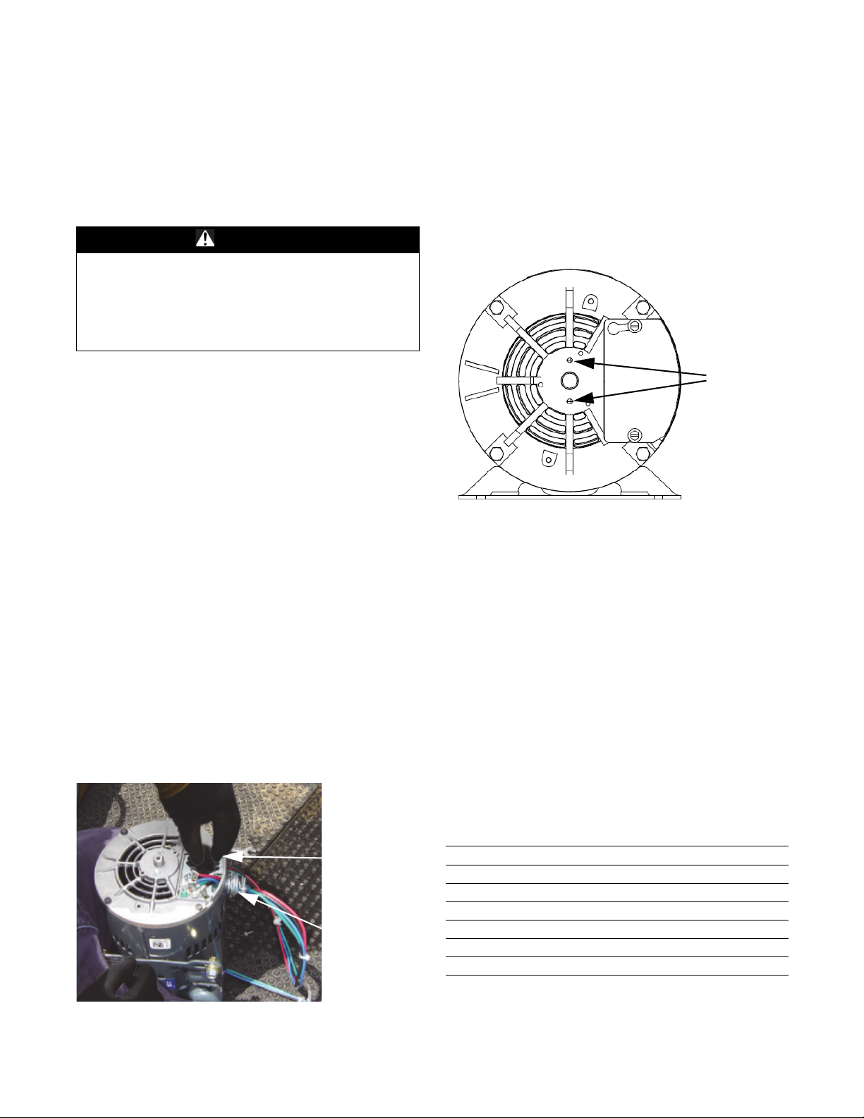
Figure 1. Inverter duty motor
e is a common component to
of the inverter duty motor.
to be connected to the motor.
motor, follow a, b, and c below to install the grounding
ring.
a. Remove the two screws from th
e back of the motor
as shown in Figure 2.
Figure 2. Back side of inverter duty motor
b. Slide the grounding ring over the end of the shaft
d ali
gn the holes in the ring with the holes that the
an
screws were in.
c. Using the screws and washers provided wi
th the
grounding ring secure the ring to the motor.
6. Install the inverter duty motor into
the unit.
7. Determine the location of the holes used to hold the
vibration bracket onto the motor mounting panel.
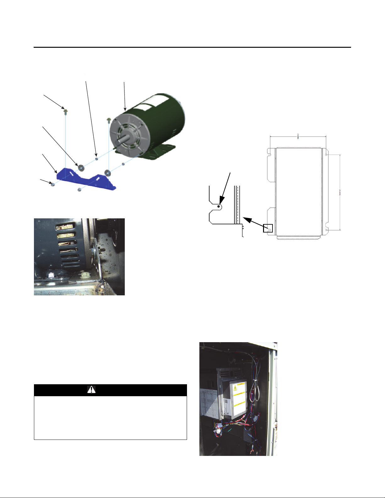
a. Dry fit the bracket according to Figure 3.
b. Use a marker to mark the lo
cation to
drill the holes
for the screws that will hold the bracket to the motor
mounting panel.
8. Drill the holes that were marked
using the 1/
8 inch drill
bit provided.
9. Install the vibration dampening bracket. See Fi
gure 3
for details.
Table 3.
Balloon Part
1 Inverter Duty Motor
2 Vibration Reduction Bracket
3 Screw, 1/4-14 X 0.625 (X25240209030)
(a)
4
(b)
5
5. For additional motor bearing protection, a motor shaft
grounding ring is provided. Before installing the
PART-SVN227B-EN 7
(a) The torque applied to the nuts on the end of the extended bolts is to
(b)Use 1 washer on each bolt for 3 and 5 HP motors.
6 Nut (attached by motor supplier)
be as follows:
18–25 in·lb (~2 ft·lb) for 3 and 5 HP motors
Nut, 10-32 Hex Lock (X28022600000)
Washer, 0.328 ID X 2.00 OD (X22050242010)
Page 8
Installation
1
2
3
4
5
6
1
6
3
5
2
4
Orient template as shown.
Marks for holes on left
side should be fully
into slots for holes
drilled on the right
side to line up
correctly.
Figure 3. Vibration bracket installation
Figure 4. 3 or 5 HP vibration bracket installed
seen in Figure 6. In order to mount the assem
in
ch holes will need to be drilled.
1. Use the paper template provid
of the four holes to be drilled. Note the location of the
temperature sensor for some gas heat units as the
wiring will need to reach around the drive assembly
after it is installed.
Figure 5.
ed to
bly four 1/8th
mark the locations
Discharge Air Sensor
For multispeed or single zone VAV operation a discharge
air sensor is required. A discharge air sensing kit ships
with each upgrade kit. Literature RT-SVN02*-EN ships
along with the discharge air sensor parts kit and should be
referenced for installation of the sensor. If a discharge air
sensor is already installed it does not need to be replaced.
VFD Assembly Mounting
Hazardous Voltage!
Failure to disconnect power before servicing could
result in death or serious injury. Disconnect all electric
power, including remote disconnects before servicing.
Follow proper lockout/tagout procedures to ensure the
power can not be inadvertently energized.
WARNING
2. After locating and drilling the four holes, screw in two
of the sheet metal screws
a small gap still remains between the bottom of the
screw head and the sheet metal wall.
3. Slide the left side of the drive assembly
for m
ounting instead of holes on to the screws that are
part way screwed in. Holding the drive in place, screw
the two screws on the left side the rest of the way
down.
4. Screw in the two screws on the
assembly.
Figure 6. Field installed VFD assembly
in the left two holes so that
that has slots
right side of the drive
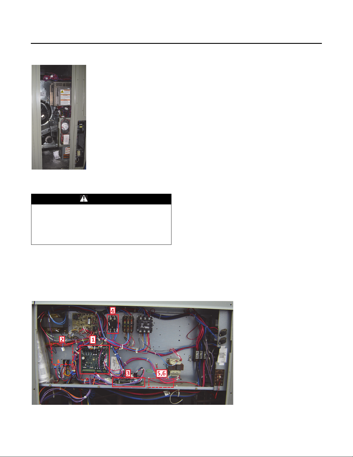
The VFD assembly is to be mounted on the interior wall in
the supply fan section using four sheet metal screws as
8 PART-SVN227B-EN
Page 9
Installation
Figure 7. Factory installed VFD assembly
Control Panel Components
WARNING
Hazardous Voltage!
Failure to disconnect power before servicing could
result in death or serious injury. Disconnect all electric
power, including remote disconnects before servicing.
Follow proper lockout/tagout procedures to ensure the
power can not be inadvertently energized.
1. Remove and replace the existing RTRM module with
the new RTRM module provided. Reconnect all plugs/
wires that were removed from the existing module to
the new module. Refer to the Control Box Connections
diagram when connecting plugs to the module.
2. Remove and replace (or add) the RTOM
the new RTOM module provided. Reconnect all plugs/
wires that were removed from the existing module to
the new module. Refer to the Control Box Connections
diagram when connecting plugs to the module.
3. Communications module location is highlighted in the
cture below. It is not necessary to add or replace the
pi
communications module for the upgrade, it will be
referred to in terms of locating the new ground
terminal and relay(s).
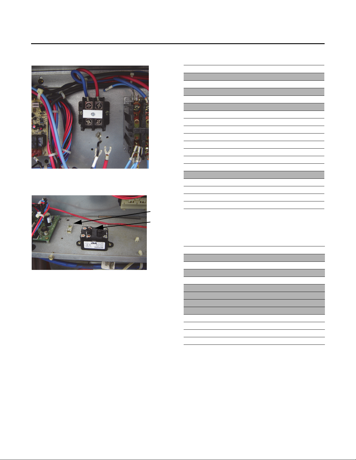
4. Remove and replace the supply fan motor contactor
with the terminal block (HTB3
most likely not be two existing holes that will line up
with the mounting holes of the terminal block. Use an
existing hole and then using a 1/8-in. drill bit drill a hole
to provide a location for the second screw. Reconnect
wires 1A, 2A, 8A and 9A after the terminal block has
been secured to the back panel. (1A to L1, 2A to L2, 8A
to T1, 9A to T2)
5. *Install the terminal st
6. *Install the relay(s) (VRR, VRS) provided. (For
Multispeed operation both r
SZVAV only one relay is needed (VRR).)
7. Replace the Economizer Module (RTEM) if the unit is
uipped
eq
Module is located behind the small access panel on the
outside of the economizer hood.
*Note:I
with an economizer. The Economizer
n units built before single zone VAV or multispeed
was available
VRR and VRS will need to be drilled using a 1/8-in.
drill bit. Positioning should be to the right of the
communications module as seen in Figure 10. If the
area to th
not available then use the area to the left of the
communications module.
e right of the communications module is
rip (GTB
from the factory, holes for the GTB,
) prov
) provided.
elays are needed, for
module with
ided. There will
Figure 8. Control panel installation
PART-SVN227B-EN 9
Page 10
Installation
GTB
VRR
Figure 9. Terminal block install
ation
Figure 10. Field installed terminal strip and relay
(SZVAV)
Table 4. Multispeed upgrade wires
Terminal Wire Number Terminal Usage
VRR-3 36CC GTB All
VSR-3 36CD GTB
RTRMP1-2 36CF GTB All
PPF7-3 36CG GTB
GV PPF10-2 36CK GTB Gas Heat
PPF27-1 600B VRR-2 All
PPF27-2 601B VRR-4 All
PPF27-3 603B VSR-5 All
PPF27-4 604B VSR-6 All
PPF27-4 604E RESISTOR All
PPF27-6 607C RESISTOR All
RTRM P2-5 608A VSR-1 All
RTRM P9-1 609A RTRM P9-2
PHM Y-OUT W38 RTRM P1-12 All
COMM PPF5-5 W63 RTOM PPF8-1 All
COMM PPF5-4 W64 RTOM PPF8-2 All
COMM PPF5-2 W65 RTOM PPF8-3 All
COMM PPF5-1 W66 RTOM PPF8-4 All
Note: -GTB = New terminal strip installed next to communications module
-VRR = New relay
-VSR = New relay (Multispeed Only)
All
Electric Heat
All
Note: For multispeed conversion the second relay (VSR)
would be installed to the right of the VRR pictured.
Wiring
The tables below contain the connection information for
the control panel wires that ship with the upgrade package
based on the type of upgrade being performed. Directions
and diagrams in the sections to follow will detail the
connections to be made.
Table 5. New wiring for SZVAV upgrade
Terminal Wire Number Terminal Usage
VRR-3 36CC GTB All
RTOM P12-2 36CE GTB
GV 36CK GTB Gas Heat
PPF7-3 36CG GTB
PPF27-1 600B VRR-2 All
PPF27-2 601B VRR-4 All
PPF27-5 604D RTOM P11-2 All
PPF27-6 607B RTOM P11-1 All
COMM PPF5-5 W63 RTOM PPF8-1 All
COMM PPF5-4 W64 RTOM PPF8-2 All
COMM PPF5-2 W65 RTOM PPF8-3 All
COMM PPF5-1 W66 RTOM PPF8-4 All
Note: -GTB = New terminal strip installed next to communications module
-VRR = New relay
-VSR = New relay (Multispeed Only)
All
Electric Heat
10 PART-SVN227B-EN
Page 11
Installation
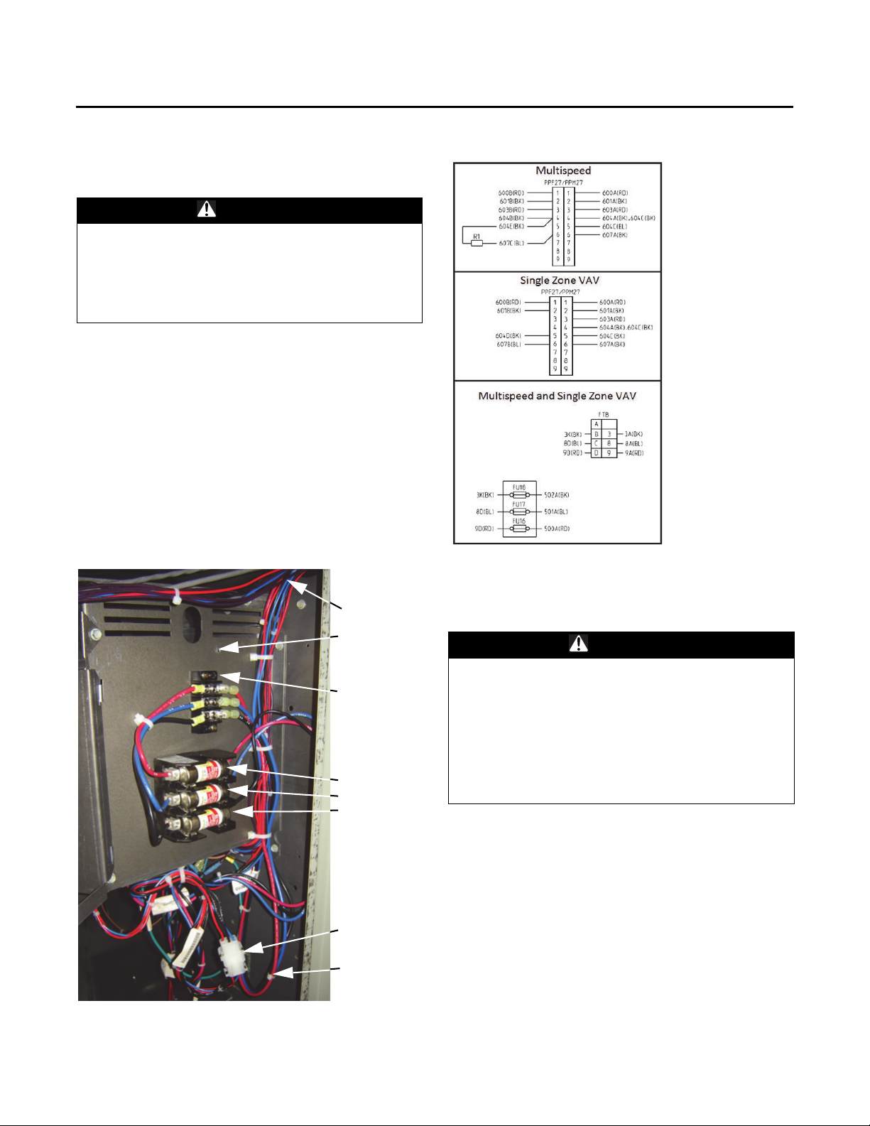
Chase to
Control Panel
Removed
Screw
FTB
FU18
FU17
FU16
Wires to run
back to the
control panel
PPF27/
PPM27
Control Panel to Drive Connections
WARNING
Hazardous Voltage!
Failure to disconnect power before servicing could
result in death or serious injury. Disconnect all electric
power, including remote disconnects before servicing.
Follow proper lockout/tagout procedures to ensure the
power can not be inadvertently energized.
1. Take the nine pin connector (PPF27) that the signal
control wires (600B, 601B etc.) are plugged into and
using steel fish tape/stick run the opposite end of that
wire harness through the wire chase that runs between
the indoor fan section and upper left hand corner of the
control panel.
2. Plug PPF27 into PPM27.
3. Remove the screw that holds
closed in order to make the power connection of wires
3A, 8A, and 9A to FTB. After the connections have been
made close the fusholder cover and re-secure it with
the screw that was removed.
the fuseholder cover
Figure 12. Control panel to drive schematic
Figure 11. Control panel to drive connections
Motor and Drive
Motor to Drive
WARNING
Proper Field Wiring and Grounding
Required!
Failure to follow code could result in death or serious
injury. All field wiring MUST be performed by qualified
personnel. Improperly installed and grounded field
wiring poses FIRE and ELECTROCUTION hazards. To
avoid these hazards, you MUST follow requirements for
field wiring installation and grounding as described in
NEC and your local/state electrical codes.
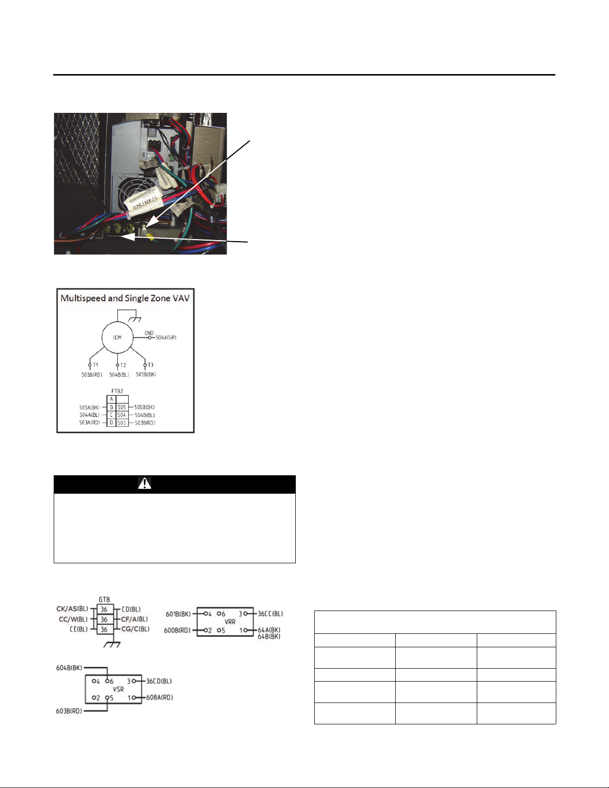
For 3 and 5 hp motors a separate harness containing wires
505B, 504B and 503B is used to connect the inverter duty
motor to terminal FTB2. After connecting the power wires,
connect the ground wire (506A) from the motor to the
ground screw on the bottom of the drive assembly.
PART-SVN227B-EN 11
Page 12
Installation
GND
FTB2
Figure 13. Motor to drive connections
Figure 14. Motor to drive schematic
Control Panel
WARNING
Hazardous Voltage!
Failure to disconnect power before servicing could
result in death or serious injury. Disconnect all electric
power, including remote disconnects before servicing.
Follow proper lockout/tagout procedures to ensure the
power can not be inadvertently energized.
Figure 15. GTB, VRR, and VSR wire connections
1. Connect the ends of the 600B and 601B to VRR
terminals 2 and 4 as shown in Figure 15, p. 12.
a. For multispeed applications conne
and 604B to VSR
terminals 5 and 6 as shown in
ct wires 603B
Figure 15, p. 12.
b. For SZVAV conversions, connect pl
ug P11 (wires
604D and 607B) to the J11 pins on the RTOM
module.
2. Connect the end of wire 64A that was connected to the
supply fan
motor contactor to VRR-1 along with w
ire
64B. (Wire 64B only applies to electric heat/cooling
only units.)
3. Remove wire 36W (one end is curr
TNS1); it is re
placed by 36CC which is included with the
ently connected to
wiring kit. Connect one end of wire 36CC to VRR
terminal 3 and the other end to the GTB.
or Multispeed conversions, take wire 36CD (suppli
4. F
ed
in wiring kit) and connect one end to terminal 3 of the
VSR and the other end to the GTB. Also, for Multispeed
conversions connect the pl
ug that jumps RTRM P9-1 to
RTRM P9-2 to the RTRM board as shown in connection
diagram 01860036.
or Multispeed conversions, connect wire 608A to
5. F
terminal 1
of the VSR. Land the other end of the 608A
on plug P2, hole 5. P2 connects to the RTRM module at
J2. To attach wire 608A to pl
ug P2, slide the press fitting
into hole 5 of P2. This connection is shown on diagram
01860036. Use this diagram to find the correct hole
location on fitting P2.
6. For SZVAV conversions take the end of wire 36CE that
has th
e 7 pin
plug and connect it to the RTOM J12
location and plug the other end on to the GTB.
7. For gas heat units connect the end of wire 36AS that
connected to th
was
e supply fan contactor to the GTB.
For electric heat units connect the end of wire 36C that
was connected to the supply fan contactor to the GTB.
8. Connect Wire 36A to the GTB. In production
ult
ispeed/SZVAV units this wire is labeled as 36CF as
M
seen in Table 5, p. 10.
Note: Wire 36CF is i
ncluded in the wiring kit as a
substitute for wire 36A however, replacement is
not necessary.
Table 6. Wire number differences
Wire Number Changes, Multispeed/SZVAV vs Constant
Volume
Multispeed/SZVAV Constant Volume Notes
36CC 36W
12 PART-SVN227B-EN
36CF 36A
36CG 36C
36CK 36AS
Wire 36CC is included
ing package
in wir
Wire 36CG is used
with elec
Wire 36CK is used
with ga
tric heat
s heat
Page 13
Installation
9. The wire harness for W63 through W66 is included
with the wiring kit along with the gender change wire
for units where an RTOM module was previously not
installed. Check the original Control Box Connections
diagram for how to use the gender change wire along
with the W63 through W66 harness to make the
connection from the RTOM J11 to Communications J2
pins. If the unit already had an RTOM and
Communications Module these wires will not be
needed.
Wiring Diagrams
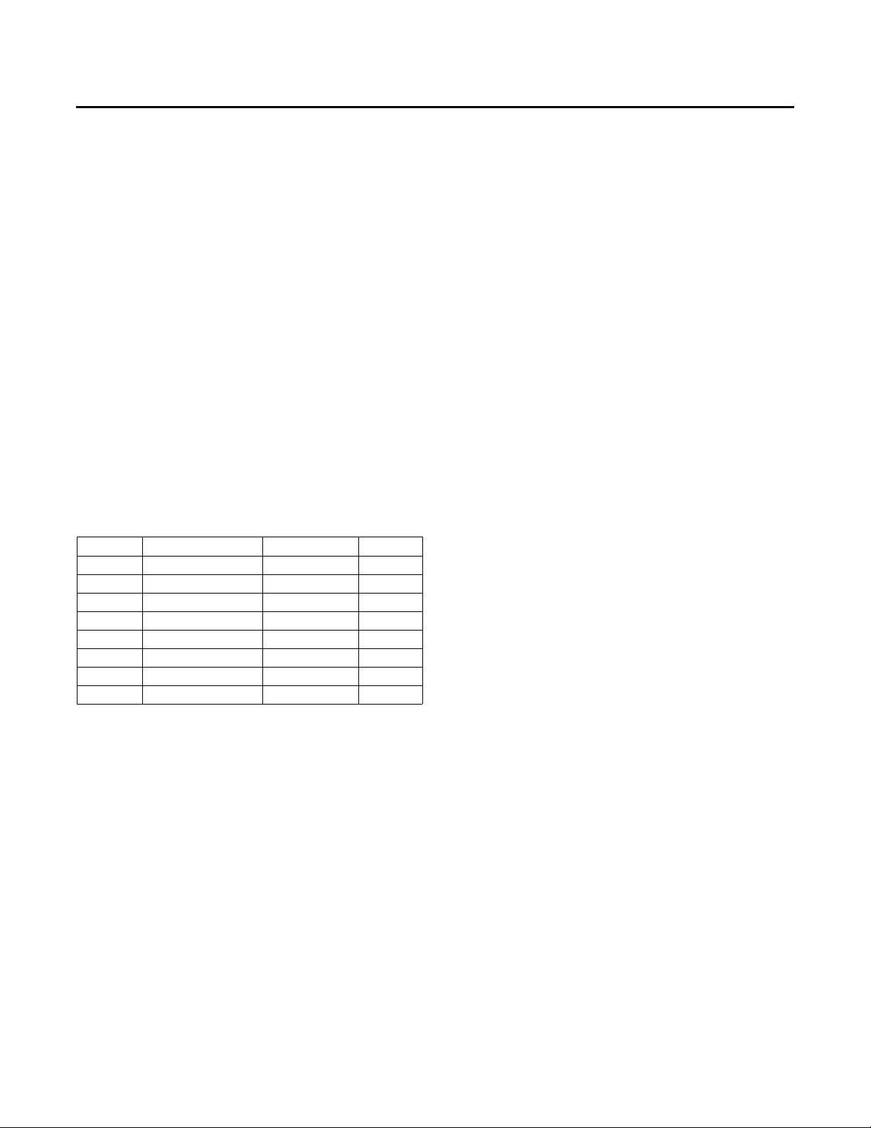
Kit 018600350100 contains the wiring diagrams seen in
Table 7. The electrical and connection schematic diagrams
are common for all units but the electrical control and
power diagrams will need to be selected based on the unit
voltage and the type of heat that the unit has. Control
electrical, power electrical and schematic electrical
diagrams can be stuck over the existing electrical
diagrams on the inside of the control panel cover however
the schematic connection should not be placed over the
existing diagram as it only has wire labels for the wiring
that was changed or added during the conversion.
(a)
Table 7. Wiring diagrams
Number Type Heat Voltage
23130064 Control Electrical Electric/None All
23130067 Control Electrical Gas All
23130053 Pow er Electrical Electric/None 208-230
23130054 Pow er Electrical Electric/None 460
23130345 Pow er Electrical Gas 208-230
23130347 Pow er Electrical Gas 460
23130376 Schematic Electrical All All
01860036 Schematic Connection All All
(a) Always refer to the most recent revision of each wiring diagram.
In addition to the wiring diagrams, affix
the name
number and serial number near the original unit
nameplate sticker.
plate sticker that contains the upgrade order
in kit 018600350100
the top section of
Setting Economizer Damper Positions
Note: New settings are needed for the economizer
damper position so that the amount of outdoor air
can keep up with the varying fan speed.
For units not configured with demand control ventilation
additio
(DCV),
outdoor airflow accuracy is supported; directions for
setting damper positions with DCV installed are included
in the DCV installation literature (ACC-SVN16*-EN). The
operation is similar to OA CFM Compensation on
nal minimum position setpoints to increase
Traditional VAV units, with the addition of a Design
Minimum Position setpoint at Middle Fan Speed
Command. The following setpoint potentiometers will be
used on the RTEM:
1. Design Min at Minimum Fan Speed Command (RTEM
DCV Min)
2. Design Min at Middle Fan Speed
DCV Setpoint LL)
3. Design Min at Full Fan Speed Command (RTEM Design
Min)
The contro
position between the user-selected setpoints based on the
supply fan speed command. By default, the Design
Minimum Position schedule is a linear line through all user
selectable Design Minimum Position setpoints. As with
Demand Controlled Ventilation, if the Design Minimum
Position at Middle fan speed command is set to a point that
would be higher than the calculated linear line between
the Design Minimum Position setpoints at Minimum and
Maximum fan speed command, the minimum position is
limited to the point that would make the Design Minimum
Position schedule linear.
Provisions have been made in Service Test Mode to allow
r prope
fo
1. To set the Design Minimum Position setpoint at
2. To set the Design Minimum Position setpoint at Middle
3. To set the Design Minimum Position setpoint at Full
ller calculates the a
r damper minimum position setup:
inimum Fa
M
(Fan ON) or Step 2 (Economizer Open) and make the
proper adjustment.
an Spe
F
make the proper adjustment.
Fan Spe
make the proper
n Speed, set the unit to operate at Step 1
ed, set the unit to operate at Step 3 (Cool 1) and
ed, set the unit to operate at Step 4 (Cool 2) and
adjustment.
ctive
Command (RTEM
OA Damper Minimum
Zone Sensor
For fully modulating Single Zone VAV operation, a zone
temperature sensor is required. A zone temperature
sensor does not ship with the upgrade kit. Wiring for the
zone temperature sensor is included with the sensor if
purchased separately.
If thermostat control is being replaced b
to achieve fully modulating single zone VAV operation, it is
possible to reuse the thermostat wires to connect in the
zone sensor. If the unit has been upgraded using the single
zone VAV parts and wiring method found in this manual,
no additional settings are needed for the unit perform as
a single zone VAV unit.
A thermostat will NOT provide fully modulating single
zone VAV contro
single zone VAV parts and wiring but still has thermostat
control, the unit will revert to 2-speed fan control unless a
zone sensor is added.
l. If the unit has been upgraded using the
y the zone sen
sor
PART-SVN227B-EN 13
Page 14

Page 15

Page 16

Trane and American Standard create comfortable, energy efficient indoor environments for commercial
and residential applications. For more information, please visit trane.com or americanstandardair.com.
Trane and American Standard have a policy of continuous product and product data improvement and reserve the right to change design and
specifications without notice. We are committed to using environmentally conscious print practices.
PART-SVN227B-EN 25 Jun 2020
Supersedes PART-SVN227A-EN (Sep 2015)
©2020
 Loading...